Electrical Circuits and Circuit Diagrams
32 Slides1,020.25 KB
Electrical Circuits and Circuit Diagrams
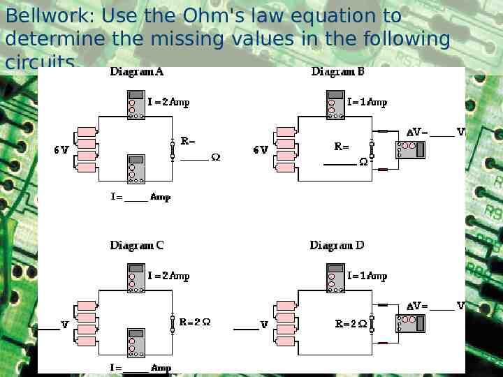
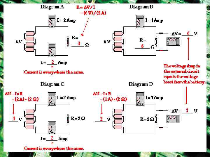
Bellwork: Use the Ohm's law equation to determine the missing values in the following circuits.
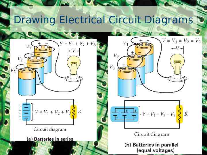
Drawing Electrical Circuit Diagrams
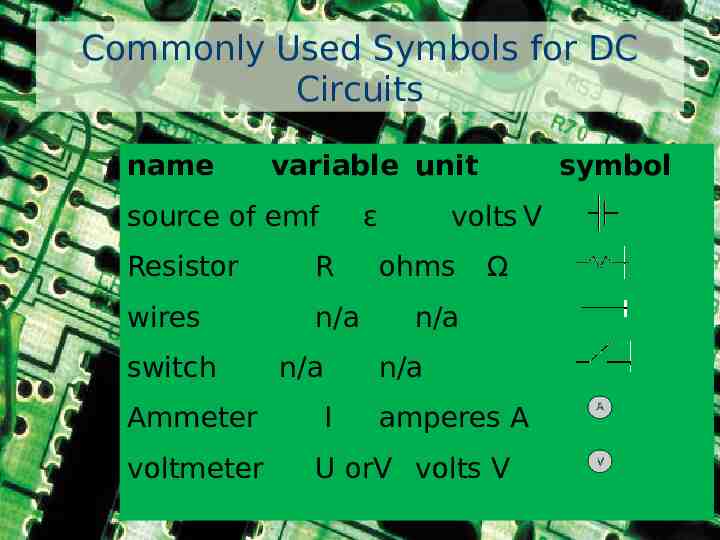
Commonly Used Symbols for DC Circuits name variable unit source of emf ε Resistor R wires n/a switch Ammeter voltmeter n/a symbol volts V ohms Ω n/a n/a I amperes A U orV volts V
1. A current is said to exist whenever . a. a wire is charged b. a battery is present c. electric charges are unbalanced d. electric charges move in a loop
2. Current has a direction. By convention, current is in the direction which . a. charges move b. - electrons move c. electrons move
3. If an electric circuit could be compared to a water circuit at a water park, then the current would be analogous to the . A. water pressure D. bottom of the slide B. gallons of water flowing down E. water pump slide per minute F. top of the slide C. water
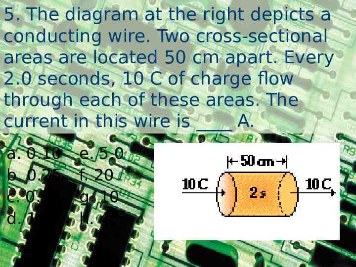
5. The diagram at the right depicts a conducting wire. Two cross-sectional areas are located 50 cm apart. Every 2.0 seconds, 10 C of charge flow through each of these areas. The current in this wire is A. a. 0.10 b. 0.25 c. 0.50 d. 1.0 e. 5.0 f. 20 g. 10 h. 40
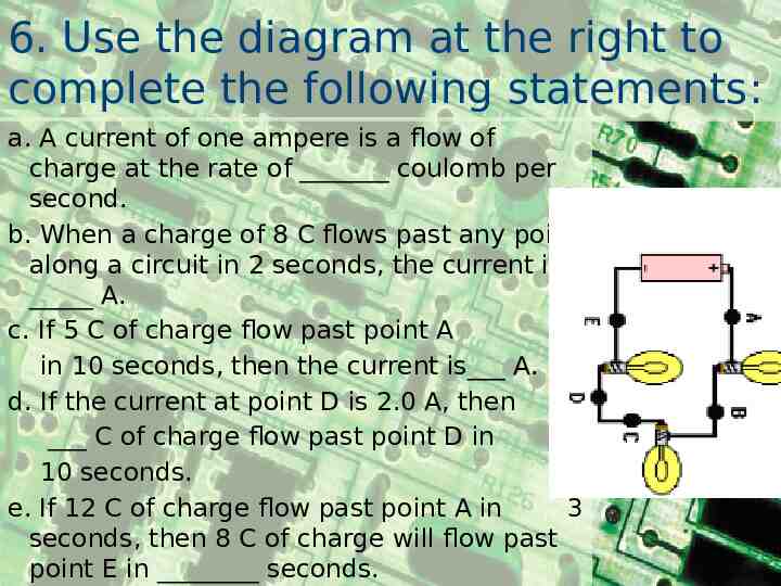
6. Use the diagram at the right to complete the following statements: a. A current of one ampere is a flow of charge at the rate of coulomb per second. b. When a charge of 8 C flows past any point along a circuit in 2 seconds, the current is A. c. If 5 C of charge flow past point A in 10 seconds, then the current is A. d. If the current at point D is 2.0 A, then C of charge flow past point D in 10 seconds. e. If 12 C of charge flow past point A in 3 seconds, then 8 C of charge will flow past point E in seconds.
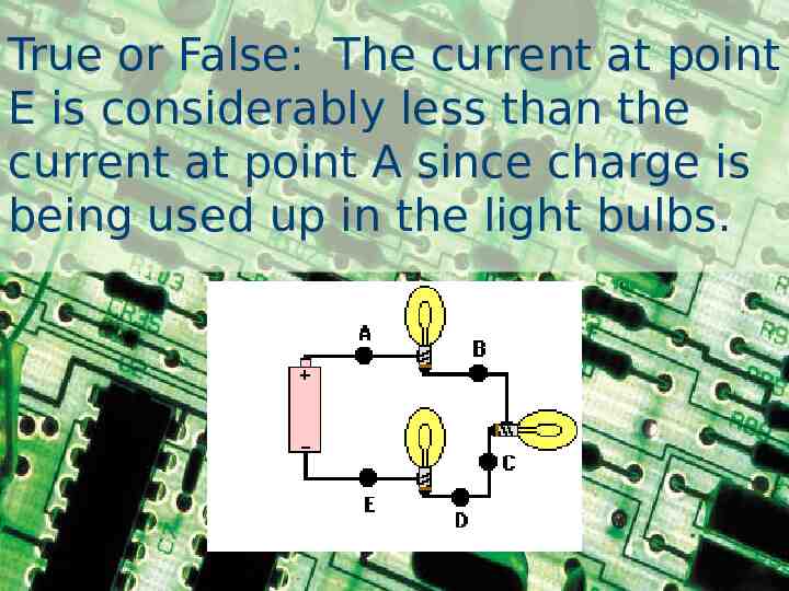
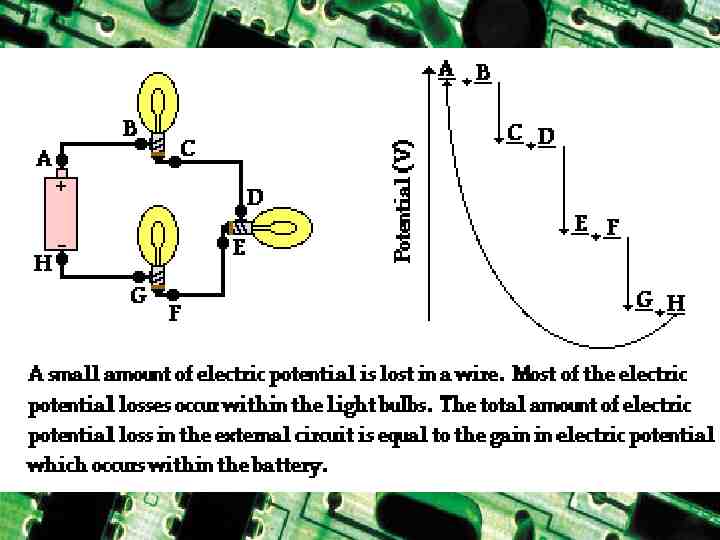
True or False: The current at point E is considerably less than the current at point A since charge is being used up in the light bulbs.
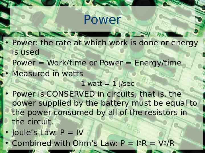
Power Power: the rate at which work is done or energy is used Power Work/time or Power Energy/time Measured in watts 1 watt 1 J/sec Power is CONSERVED in circuits; that is, the power supplied by the battery must be equal to the power consumed by all of the resistors in the circuit. Joule’s Law: P IV Combined with Ohm’s Law: P I2R V2/R
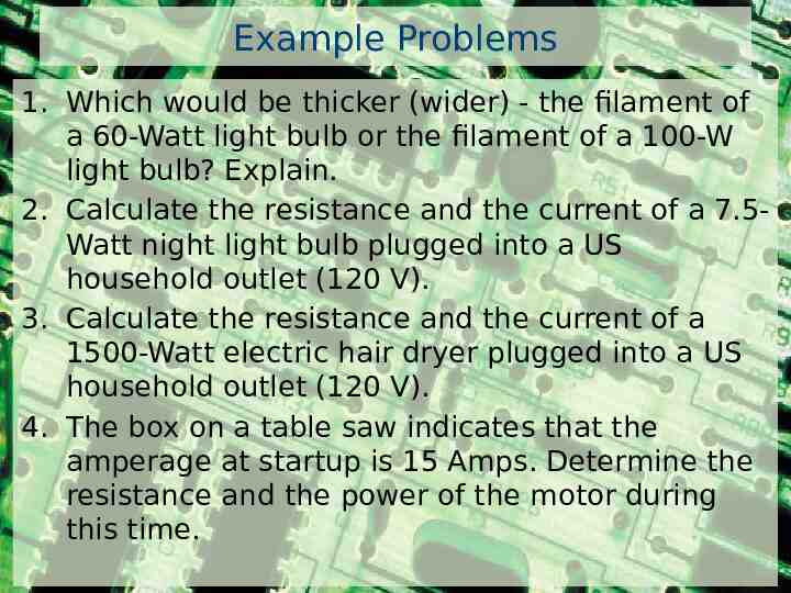
Example Problems 1. Which would be thicker (wider) - the filament of a 60-Watt light bulb or the filament of a 100-W light bulb? Explain. 2. Calculate the resistance and the current of a 7.5Watt night light bulb plugged into a US household outlet (120 V). 3. Calculate the resistance and the current of a 1500-Watt electric hair dryer plugged into a US household outlet (120 V). 4. The box on a table saw indicates that the amperage at startup is 15 Amps. Determine the resistance and the power of the motor during this time.
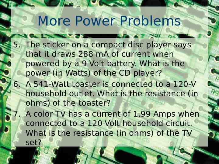
More Power Problems 5. The sticker on a compact disc player says that it draws 288 mA of current when powered by a 9 Volt battery. What is the power (in Watts) of the CD player? 6. A 541-Watt toaster is connected to a 120-V household outlet. What is the resistance (in ohms) of the toaster? 7. A color TV has a current of 1.99 Amps when connected to a 120-Volt household circuit. What is the resistance (in ohms) of the TV set?
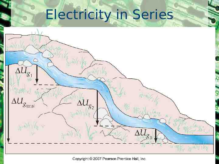
Electricity in Series
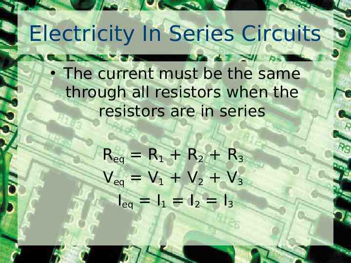
Electricity In Series Circuits The current must be the same through all resistors when the resistors are in series Req R1 R2 R3 Veq V1 V2 V3 Ieq I1 I2 I3
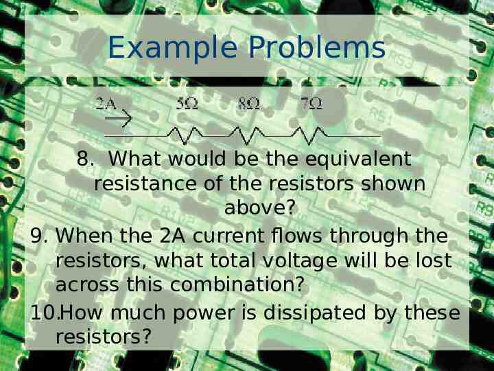
Example Problems 8. What would be the equivalent resistance of the resistors shown above? 9. When the 2A current flows through the resistors, what total voltage will be lost across this combination? 10.How much power is dissipated by these resistors?
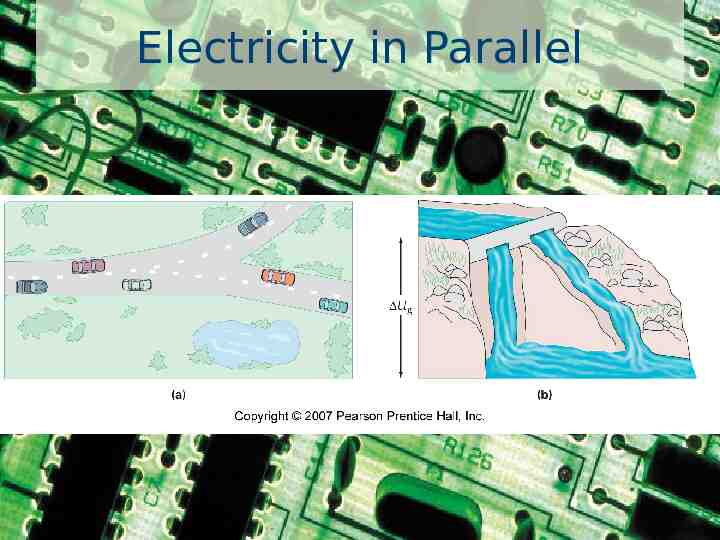
Electricity in Parallel
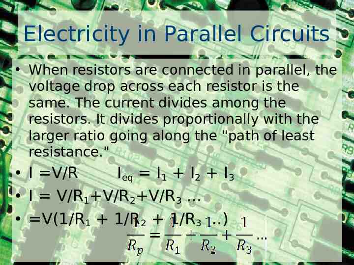
Electricity in Parallel Circuits When resistors are connected in parallel, the voltage drop across each resistor is the same. The current divides among the resistors. It divides proportionally with the larger ratio going along the "path of least resistance." I V/R Ieq I1 I2 I3 I V/R1 V/R2 V/R3 V(1/R1 1/R2 1/R3 )
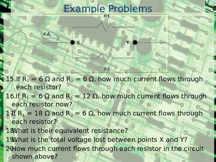
Example Problems 15.If R1 6 Ω and R2 6 Ω, how much current flows through each resistor? 16.If R1 6 Ω and R2 12 Ω, how much current flows through each resistor now? 17. If R1 18 Ω and R2 6 Ω, how much current flows through each resistor? 18. What is their equivalent resistance? 19. What is the total voltage lost between points X and Y? 20. How much current flows through each resistor in the circuit shown above?
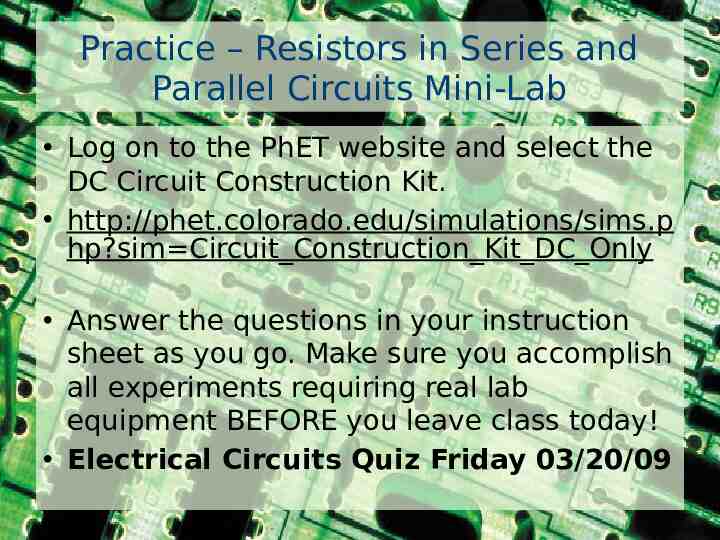
Practice – Resistors in Series and Parallel Circuits Mini-Lab Log on to the PhET website and select the DC Circuit Construction Kit. http://phet.colorado.edu/simulations/sims.p hp?sim Circuit Construction Kit DC Only Answer the questions in your instruction sheet as you go. Make sure you accomplish all experiments requiring real lab equipment BEFORE you leave class today! Electrical Circuits Quiz Friday 03/20/09
WarmUp A color TV has a current of 1.99 Amps when connected to a 120-Volt household circuit. What is the resistance (in ohms) of the TV set?
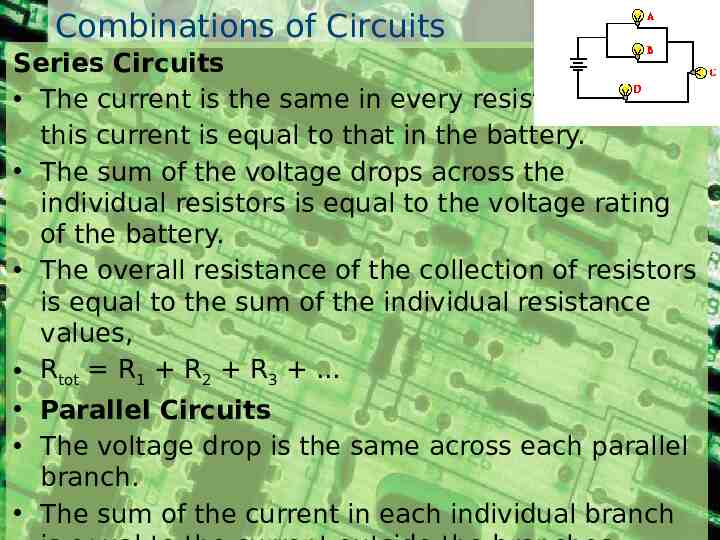
Combinations of Circuits Series Circuits The current is the same in every resistor; this current is equal to that in the battery. The sum of the voltage drops across the individual resistors is equal to the voltage rating of the battery. The overall resistance of the collection of resistors is equal to the sum of the individual resistance values, Rtot R1 R2 R3 . Parallel Circuits The voltage drop is the same across each parallel branch. The sum of the current in each individual branch
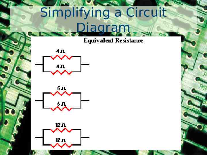
Simplifying a Circuit Diagram
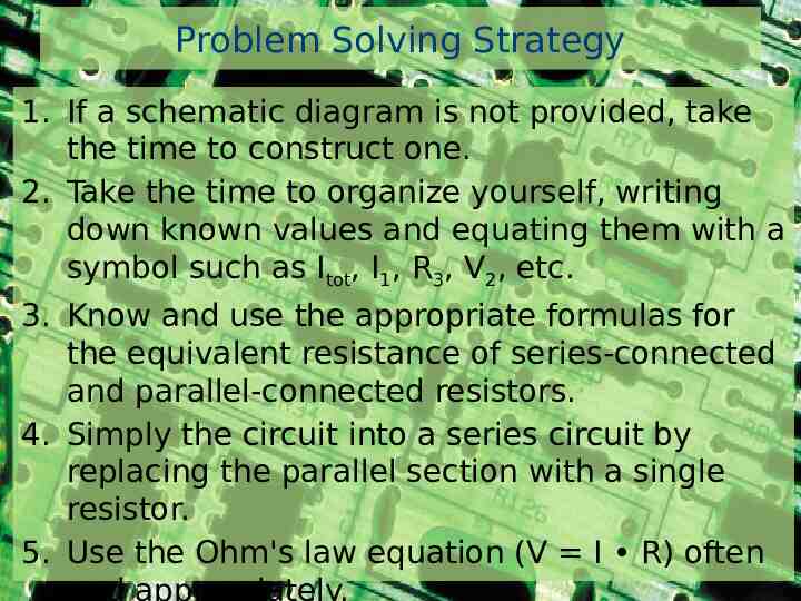
Problem Solving Strategy 1. If a schematic diagram is not provided, take the time to construct one. 2. Take the time to organize yourself, writing down known values and equating them with a symbol such as Itot, I1, R3, V2, etc. 3. Know and use the appropriate formulas for the equivalent resistance of series-connected and parallel-connected resistors. 4. Simply the circuit into a series circuit by replacing the parallel section with a single resistor. 5. Use the Ohm's law equation (V I R) often and appropriately.
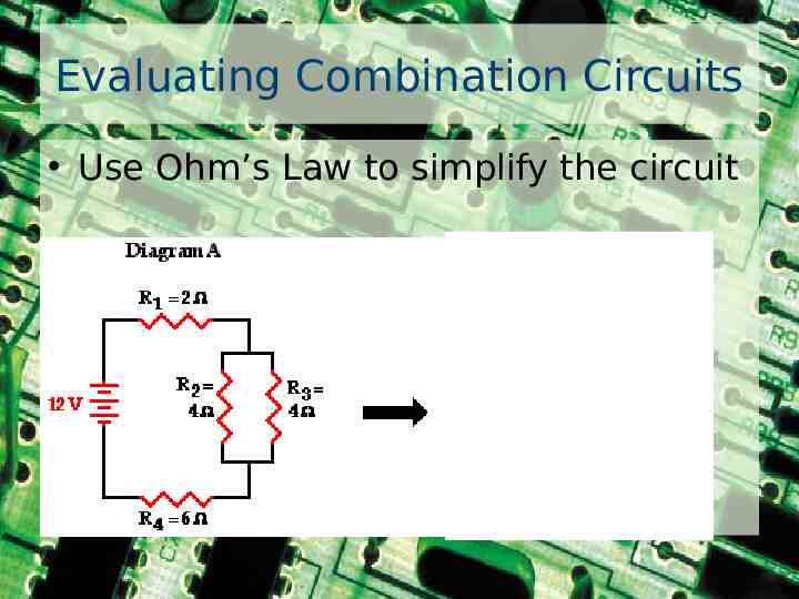
Evaluating Combination Circuits Use Ohm’s Law to simplify the circuit
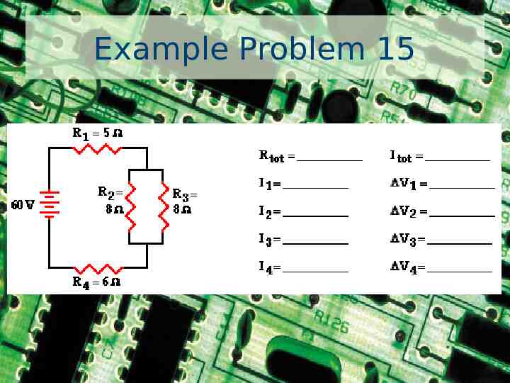
Example Problem 15
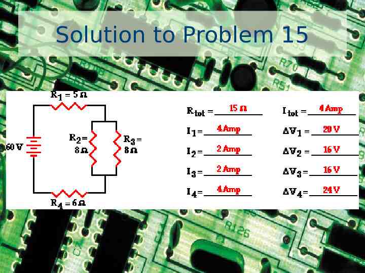
Solution to Problem 15
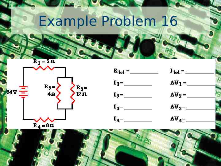
Example Problem 16
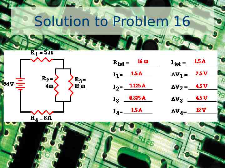
Solution to Problem 16
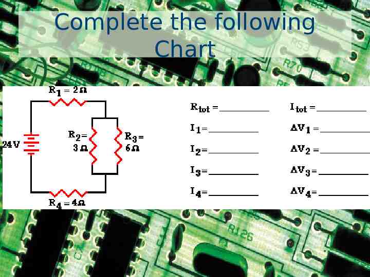
Complete the following Chart