ECE 476 POWER SYSTEM ANALYSIS Lecture 6 Development of
35 Slides6.51 MB
ECE 476 POWER SYSTEM ANALYSIS Lecture 6 Development of Transmission Line Models Professor Tom Overbye Department of Electrical and Computer Engineering
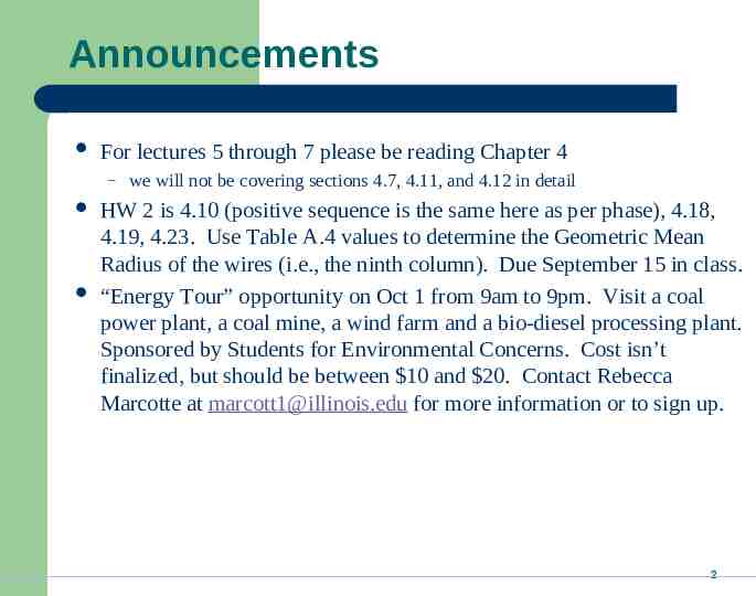
Announcements For lectures 5 through 7 please be reading Chapter 4 – we will not be covering sections 4.7, 4.11, and 4.12 in detail HW 2 is 4.10 (positive sequence is the same here as per phase), 4.18, 4.19, 4.23. Use Table A.4 values to determine the Geometric Mean Radius of the wires (i.e., the ninth column). Due September 15 in class. “Energy Tour” opportunity on Oct 1 from 9am to 9pm. Visit a coal power plant, a coal mine, a wind farm and a bio-diesel processing plant. Sponsored by Students for Environmental Concerns. Cost isn’t finalized, but should be between 10 and 20. Contact Rebecca Marcotte at [email protected] for more information or to sign up. 2
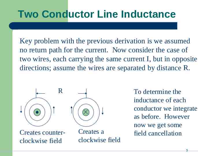
Two Conductor Line Inductance Key problem with the previous derivation is we assumed no return path for the current. Now consider the case of two wires, each carrying the same current I, but in opposite directions; assume the wires are separated by distance R. R Creates counterclockwise field Creates a clockwise field To determine the inductance of each conductor we integrate as before. However now we get some field cancellation 3
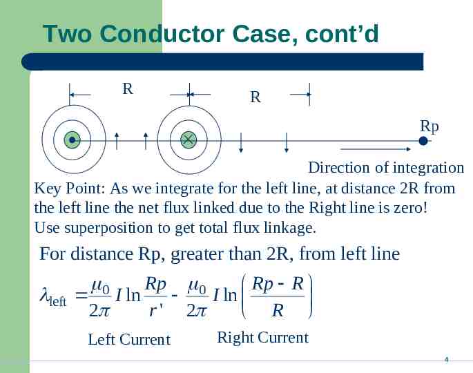
Two Conductor Case, cont’d R R Rp Direction of integration Key Point: As we integrate for the left line, at distance 2R from the left line the net flux linked due to the Right line is zero! Use superposition to get total flux linkage. For distance Rp, greater than 2R, from left line left 0 Rp 0 Rp R I ln I ln 2 r ' 2 R Left Current Right Current 4
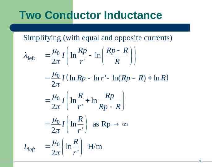
Two Conductor Inductance Simplifying (with equal and opposite currents) left Lleft 0 Rp Rp R I ln ln 2 r ' R 0 I ln Rp ln r ' ln( Rp R ) ln R 2 0 R Rp I ln ln 2 r ' Rp R 0 R I ln as Rp 2 r ' 0 R ln H/m 2 r ' 5
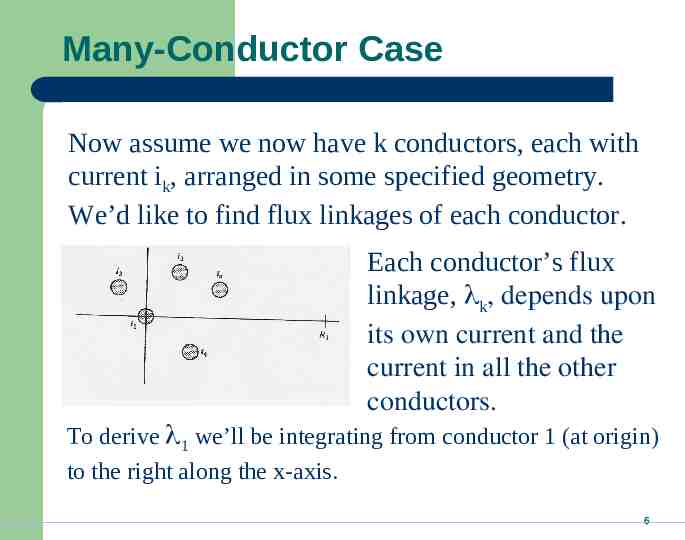
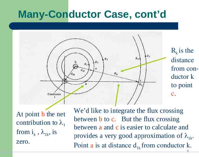
Many-Conductor Case Now assume we now have k conductors, each with current ik, arranged in some specified geometry. We’d like to find flux linkages of each conductor. Each conductor’s flux linkage, k, depends upon its own current and the current in all the other conductors. To derive 1 we’ll be integrating from conductor 1 (at origin) to the right along the x-axis. 6
Many-Conductor Case, cont’d Rk is the distance from conductor k to point c. At point b the net contribution to 1 from ik , 1k, is zero. We’d like to integrate the flux crossing between b to c. But the flux crossing between a and c is easier to calculate and provides a very good approximation of 1k. Point a is at distance d1k from conductor k. 7
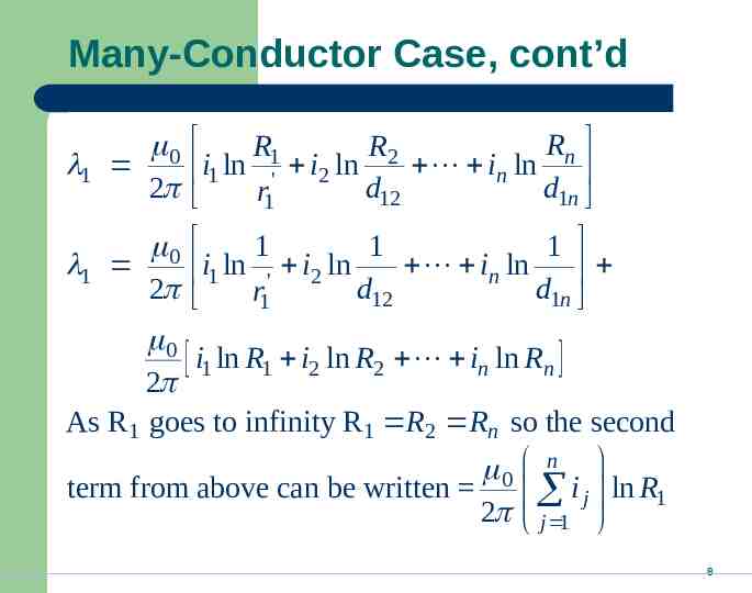
Many-Conductor Case, cont’d Rn R1 R2 i1 ln ' i2 ln d in ln d r1 12 1n 0 1 1 1 1 in ln i1 ln ' i2 ln 2 d12 d1n r1 0 i1 ln R1 i2 ln R2 in ln Rn 2 As R1 goes to infinity R1 R2 Rn so the second 0 n term from above can be written i j ln R1 2 j 1 0 1 2 8
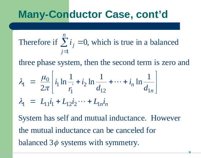
Many-Conductor Case, cont’d Therefore if n i j 0, which is true in a balanced j 1 three phase system, then the second term is zero and 1 1 1 in ln i1 ln ' i2 ln d12 d1n r1 1 L11i1 L12i2 L1nin 0 1 2 System has self and mutual inductance. However the mutual inductance can be canceled for balanced 3 systems with symmetry. 9
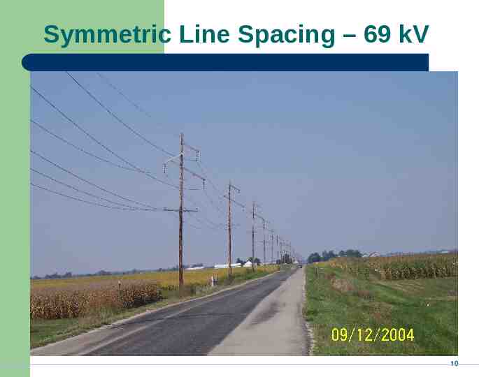
Symmetric Line Spacing – 69 kV 10
Birds Do Not Sit on the Conductors 11
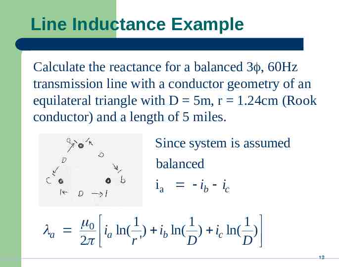
Line Inductance Example Calculate the reactance for a balanced 3 , 60Hz transmission line with a conductor geometry of an equilateral triangle with D 5m, r 1.24cm (Rook conductor) and a length of 5 miles. Since system is assumed balanced i a ib ic 0 a 2 i ln( 1 ) i ln( 1 ) i ln( 1 ) c a r ' b D D 12
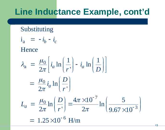
Line Inductance Example, cont’d Substituting ia ib ic Hence 0 1 1 a ia ln ia ln 2 r ' D 0 D ia ln 2 r ' 0 D 4 10 7 5 La ln ln 3 2 r ' 2 9.67 10 1.25 10 6 H/m 13
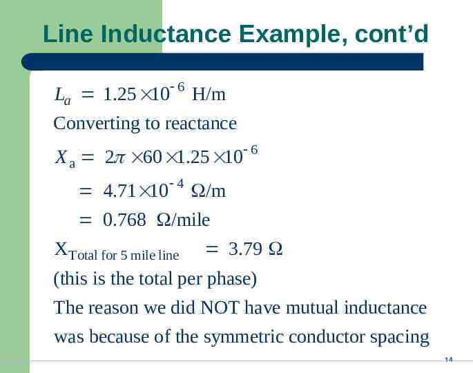
Line Inductance Example, cont’d La 1.25 10 6 H/m Converting to reactance X a 2 60 1.25 10 6 4.71 10 4 /m 0.768 /mile X Total for 5 mile line 3.79 (this is the total per phase) The reason we did NOT have mutual inductance was because of the symmetric conductor spacing 14
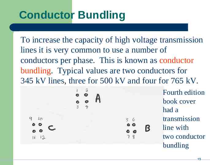
Conductor Bundling To increase the capacity of high voltage transmission lines it is very common to use a number of conductors per phase. This is known as conductor bundling. Typical values are two conductors for 345 kV lines, three for 500 kV and four for 765 kV. Fourth edition book cover had a transmission line with two conductor bundling 15
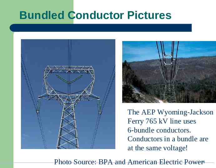
Bundled Conductor Pictures The AEP Wyoming-Jackson Ferry 765 kV line uses 6-bundle conductors. Conductors in a bundle are at the same voltage! Photo Source: BPA and American Electric Power16
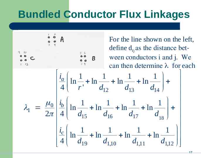
Bundled Conductor Flux Linkages For the line shown on the left, define dij as the distance between conductors i and j. We can then determine for each i 1 1 1 1 ln ln a ln ln d12 d13 d14 4 r' 0 ib 1 1 1 1 1 ln ln ln ln 2 4 d15 d16 d17 d18 ic 1 1 1 1 ln ln ln ln d1,10 d1,11 d1,12 4 d19 17
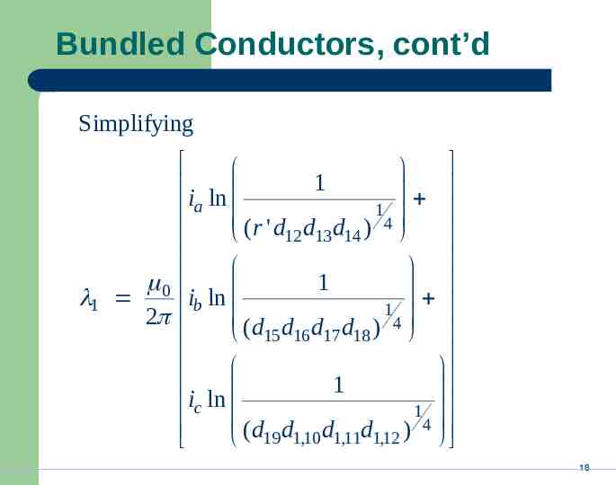
Bundled Conductors, cont’d Simplifying 1 i ln 1 a 4 (r ' d12 d13d14 ) 0 1 1 i ln b 2 ( d d d d ) 14 15 16 17 18 1 ic ln 1 4 ( d d d d ) 19 1,10 1,11 1,12 18
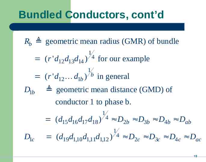
Bundled Conductors, cont’d Rb geometric mean radius (GMR) of bundle (r ' d12 d13d14 ) (r ' d12 d1b D1b 1 4 1 ) b for our example in general geometric mean distance (GMD) of conductor 1 to phase b. ( d15 d16 d17 d18 ) D1c 1 4 D2b D3b D4b Dab (d19 d1,10 d1,11d1,12 ) 1 4 D2c D3c D4c Dac 19
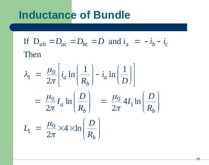
Inductance of Bundle If Dab Dac Dbc D and i a ib ic Then 1 0 1 1 ia ln ia ln 2 D Rb D 0 I a ln 2 Rb D 0 4 I1 ln 2 Rb D 0 L1 4 ln 2 Rb 20
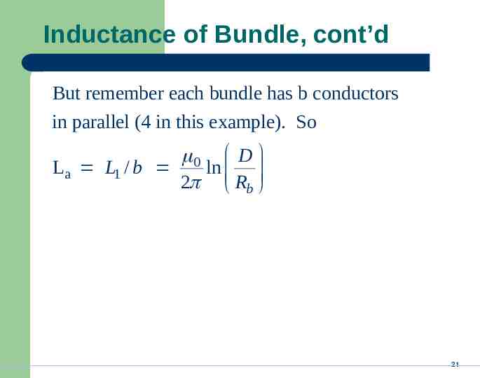
Inductance of Bundle, cont’d But remember each bundle has b conductors in parallel (4 in this example). So 0 D La L1 / b ln 2 Rb 21
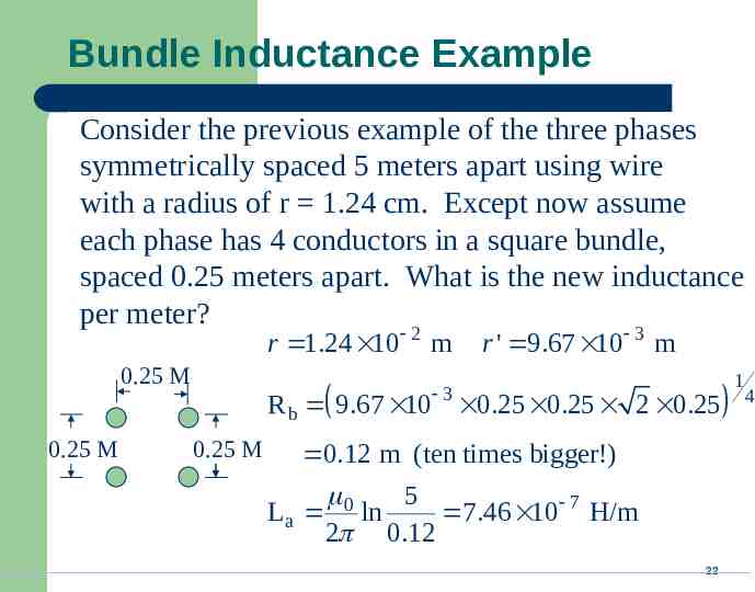
Bundle Inductance Example Consider the previous example of the three phases symmetrically spaced 5 meters apart using wire with a radius of r 1.24 cm. Except now assume each phase has 4 conductors in a square bundle, spaced 0.25 meters apart. What is the new inductance per meter? r 1.24 10 2 m 0.25 M 0.25 M r ' 9.67 10 3 m 3 R b 9.67 10 0.25 0.25 2 0.25 0.25 M 0.12 m (ten times bigger!) 0 5 La ln 7.46 10 7 H/m 2 0.12 22 1 4
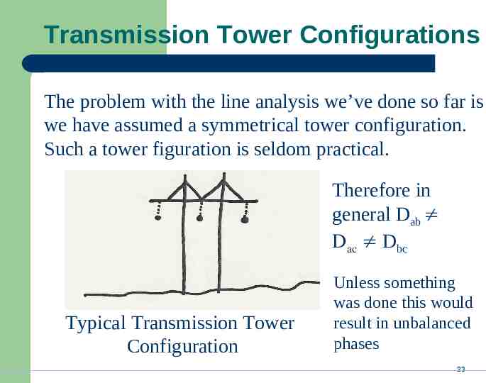
Transmission Tower Configurations The problem with the line analysis we’ve done so far is we have assumed a symmetrical tower configuration. Such a tower figuration is seldom practical. Therefore in general Dab Dac Dbc Typical Transmission Tower Configuration Unless something was done this would result in unbalanced phases 23
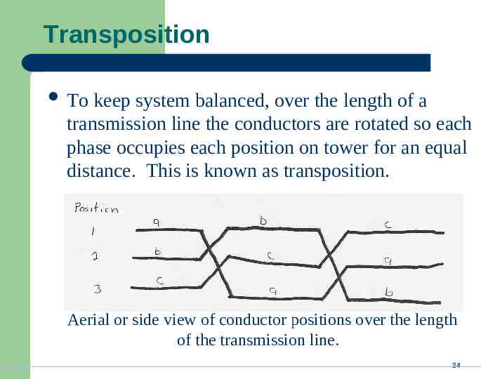
Transposition To keep system balanced, over the length of a transmission line the conductors are rotated so each phase occupies each position on tower for an equal distance. This is known as transposition. Aerial or side view of conductor positions over the length of the transmission line. 24
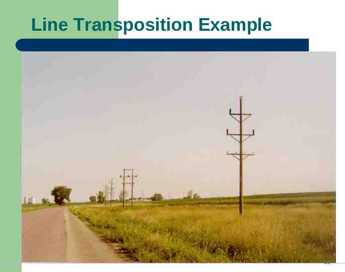
Line Transposition Example 25
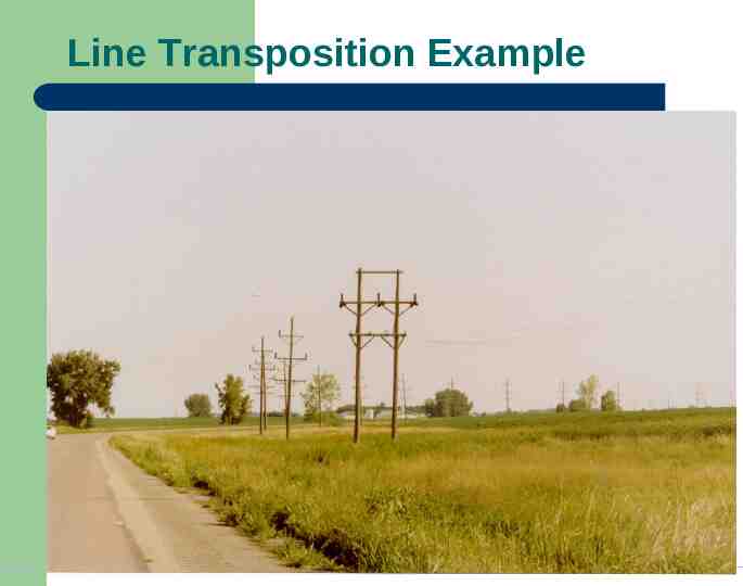
Line Transposition Example 26
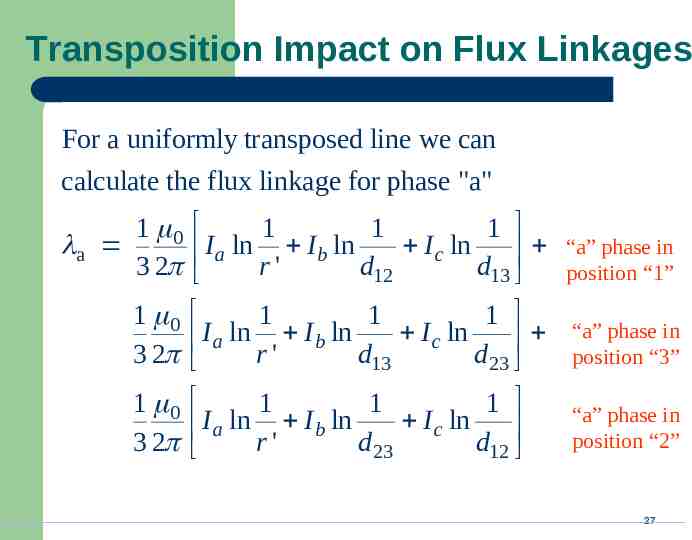
Transposition Impact on Flux Linkages For a uniformly transposed line we can calculate the flux linkage for phase "a" 1 0 a 3 2 1 1 1 I a ln r ' I b ln d I c ln d 12 13 1 0 1 1 1 I a ln I b ln I c ln 3 2 r' d13 d 23 1 0 3 2 1 1 1 I a ln r ' I b ln d I c ln d 23 12 “a” phase in position “1” “a” phase in position “3” “a” phase in position “2” 27
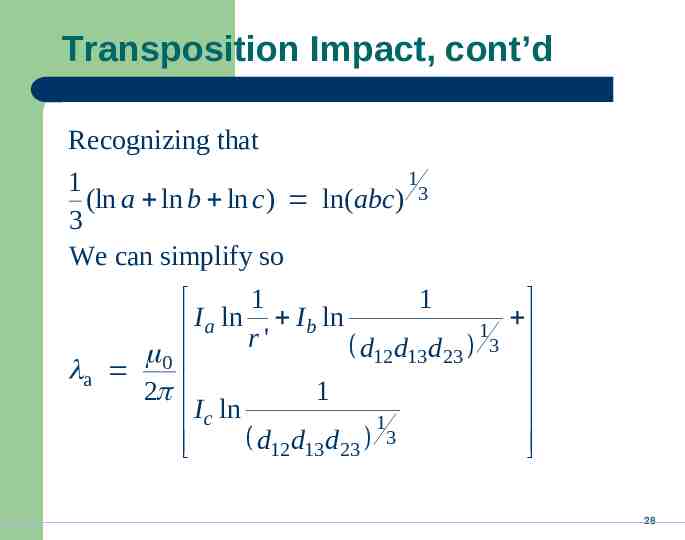
Transposition Impact, cont’d Recognizing that 1 1 (ln a ln b ln c) ln(abc) 3 3 We can simplify so 1 I ln 1 I ln 1 a r' b d12 d13d 23 3 0 a 2 1 I c ln 1 d12 d13d 23 3 28
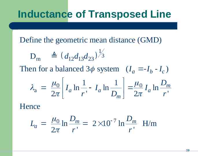
Inductance of Transposed Line Define the geometric mean distance (GMD) Dm d12 d13d 23 1 3 Then for a balanced 3 system ( I a - I b - I c ) 0 a 2 Dm 1 1 0 I a ln r ' I a ln D 2 I a ln r ' m Hence 0 Dm Dm 7 La ln 2 10 ln H/m 2 r' r' 29
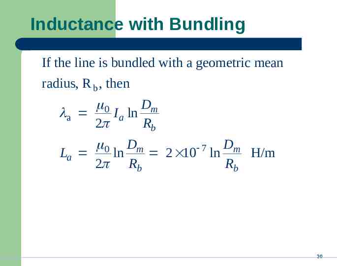
Inductance with Bundling If the line is bundled with a geometric mean radius, R b , then 0 Dm a I a ln 2 Rb 0 Dm Dm 7 La ln 2 10 ln H/m 2 Rb Rb 30
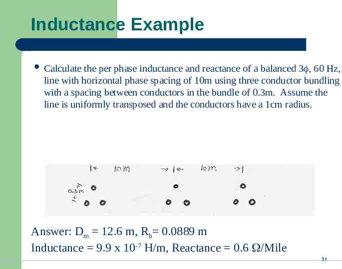
Inductance Example Calculate the per phase inductance and reactance of a balanced 3 , 60 Hz, line with horizontal phase spacing of 10m using three conductor bundling with a spacing between conductors in the bundle of 0.3m. Assume the line is uniformly transposed and the conductors have a 1cm radius. Answer: Dm 12.6 m, Rb 0.0889 m Inductance 9.9 x 10⁻⁷ H/m, Reactance 0.6 /Mile 31
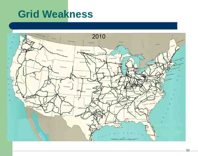
Grid Weakness 32
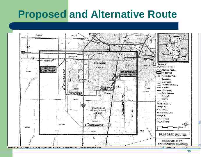
New Southwest Campus 138 kV Line In 2010 Ameren proposed building a new 138 kV transmission between the Southwest Campus and Bondville Substations Project cost is estimated to be about 14 million using the “preferred” nine mile route. An alternative seventeen mile route would cost about 22 million. Project should begin in 2012 and finish by 2014. Campus also wants to install at 138 kV line between Southwest Campus and North Champaign substations. 33
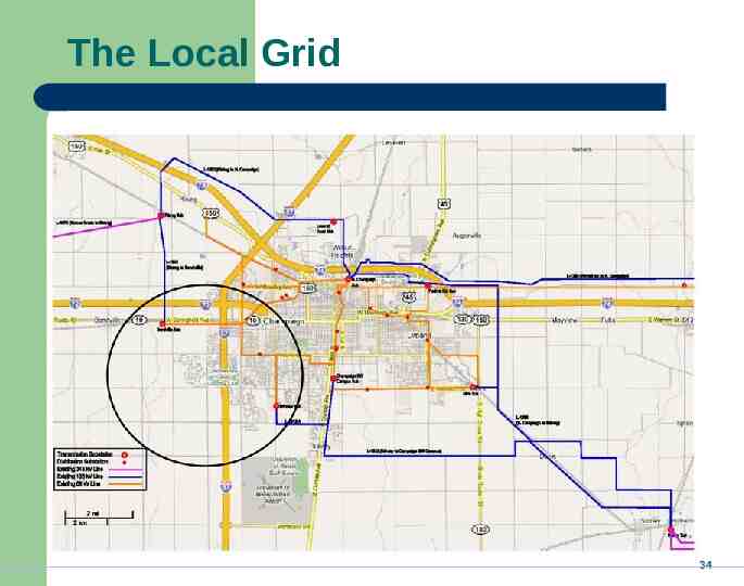
The Local Grid 34
Proposed and Alternative Route 35