Unrestricted Automation and Motion PID Basics


41 Slides593.50 KB
Unrestricted Automation and Motion PID Basics
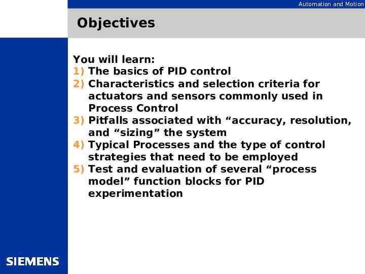
Automation and Motion Objectives You will learn: 1) The basics of PID control 2) Characteristics and selection criteria for actuators and sensors commonly used in Process Control 3) Pitfalls associated with “accuracy, resolution, and “sizing” the system 4) Typical Processes and the type of control strategies that need to be employed 5) Test and evaluation of several “process model” function blocks for PID experimentation
Automation and Motion Sessions Session 1 – Basic PID Introduction What is PID control? Designing the Process and sensor actuator selection Sizing, scaling, accuracy, resolution and other topics
Automation and Motion Session 2 Session 2 – Setting up and tuning a basic PID Loop What is Proportional control, Integral control, derivative control? Temperature control as the basic strategy.
Automation and Motion Session 3 – Tailoring the loop Session 3 – discussion about “customizing” the control loop strategy to meet the needs of the user application. Operator involvement in the setup and operation of the PID loop. Operating modes, mode control, setpoint handling and alarms. Bumpless transfers
Automation and Motion Session 4 –PV and loop algorithm Options Session 4 – Configuring the Process variable options. Engineering units and “loop normalization”- Real world versus normalized inputs. Loop algorithm options. What do they do and why are they there?
Automation and Motion Session 5 – Using STEP and Pulse output formats Now we will examine the PID loop formats that use a step output or a pulse output format. What processes and actuators are applicable here and what kinds of processes are involved. Are there any special considerations we need to take into account? Using the STEP and Pulse mode controllers
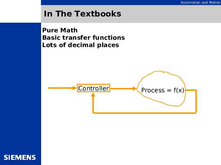
Automation and Motion In The Textbooks Pure Math Basic transfer functions Lots of decimal places Controller Process f(x)
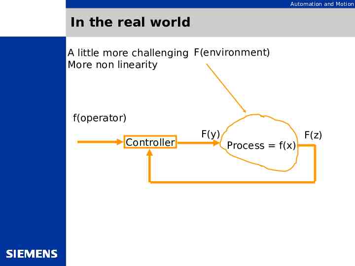
Automation and Motion In the real world A little more challenging F(environment) More non linearity f(operator) Controller F(y) Process f(x) F(z)
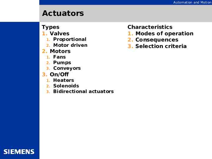
Automation and Motion Actuators Types 1. Valves 1. 2. Proportional Motor driven 2. Motors 1. 2. 3. Fans Pumps Conveyors 3. On/Off 1. 2. 3. Heaters Solenoids Bidirectional actuators Characteristics 1. Modes of operation 2. Consequences 3. Selection criteria
Automation and Motion Sensors What are you measuring? Temperature Pressure Flow Position or speed Specialty measurements PH Salinity Specific Gravity What are the Key Specs? Accuracy Resolution Linearity Span Sample Rate Environmental concerns
Automation and Motion Measuring Temperature – 80% Thermocouples Types Selection Criteria Installation and wiring
Automation and Motion PID (Proportional-Integral-Derivative) PID Simply refers to the type of action used to control such modulating equipment as valves, dampers, and variable speed devices. Also known as “Closed Loop” control. Proportional Band 100/gain Integral 1/reset Derivative rate (units of time) (units of time) Proportional Band vs Gain. On a controller using the “gain” setting, increasing this makes the loop more sensitive and less stable. While decreasing the “band” on a controller using “band” will have the same effect.
Automation and Motion Proportional Control Proportional only control is a control signal based on the difference between an actual condition and a desired condition (setpoint). The difference between the actual condition and the setpoint is Error. (Error setpointmeasurement)
Automation and Motion Weaknesses of Proportional Only Control The control device creates an output signal related directly to the error’s magnitude. The weakness of proportional control is that it requires a significant error condition to create an output. Because of this, a proportional only control can never actually achieve the desired condition. Some small amount of error, known as system “offset,” is always present.
Automation and Motion Integral Action. Integral adds an integrating term that observes how long the error condition has existed, summing the error over time. The summation value becomes the basis for an additional control signal, which is added to the signal produced by the proportional term. The goal is to eliminate offset.
Automation and Motion Proportional Integral Control PI Control can: Respond to the presence of error in the control loop. Relate the magnitude of the control signal to that error. Respond to the offset over time to achieve zero error. What about overshoot? (1/4 wave decay)
Automation and Motion Proportional Integral Derivative Derivative provides an anticipatory function that exerts a “braking” action on the control loop. The derivative is based on the error’s rate of change. (The progress of the system towards setpoint). It observes how fast the actual condition approaches that desired, producing a control action based on this rate of change. The derivative counteracts the control signal produced by the P I term. The goal is reduction in overshoot!! The derivative can slow overall response but this is the price for loop stability.
Automation and Motion Nirvana When combined, the proportional, integral, and derivative actions provide quick response to error, close adherence to setpoint, and control stability.
Automation and Motion Temperature Control Majority of controllers are temperature controllers. Slow Non-linear Usually non-symmetrical (different responses when heating up and cooling down.)
Automation and Motion Thermocouples Thermocouples (TC) – Sensors which utilize the different potential of two different metals (metal alloys). These are electrically connected at one end and if different temperatures are present at the beginning and the end of the conductors a voltage is produced. The larger the temperature difference, the larger the voltage. This relationship is non-linear. When dealing with thermocouples: Grounded or ungrounded? Cold junction compensation? EMI? Small voltages. Should I use a transmitter? Mounting location?
Automation and Motion RTD’s RTD’s (Resistance Temperature Devices – Sensors which measure the resistance of particular alloys which deliver different resistance values when the temperature changes. The most common is the PT100. In order to measure resistance, a constant current is converted into a temperature dependent voltage. This relationship is non-linear. When dealing with RTD’s: No cold junction but the applied current heats the RTD. Larger than TC’s. Poor dynamic response compared to a TC. More accurate. Line resistances.
Automation and Motion Pressure Control Fast Gauge Pressure Differential Pressure (orifice plates, Pitot tubes) Shut down mechanisms.
Automation and Motion Flow Control Fast Flow problems are often blamed on the controller!! Unlike pressure, flow is a sample measurement.
Automation and Motion Level Control Possibly the easiest to control (P or PI). Many loops are storage and not part of the process.
Automation and Motion The Good, the Bad, and the Ugly. There is no industry standard for PID. Different manufacturers of controllers use different PID algorithms and sometimes have several algorithms available within their own product lines. Algorithm-The mathematical link between the error signal and the manipulated variable. The three main classifications are: Series Ideal Parallel Again, manufacturers vary on their names for these categories. The only way to really tell which one you have is to look at the equation for the controller.
Automation and Motion Cascade Control Two controllers connected in series. The output of one controller (master) becomes the setpoint of the other controller (slave). The main value of having secondary (slave) controllers is that they act as the first line of defense against disturbances, preventing these upsets from entering the primary process. Why not use two separate controllers?
Automation and Motion Cascade Control-The goods and bads. Disturbances affecting the secondary variable can be corrected by the secondary controller before a pronounced influence is felt by the primary variable. Closing the control loop around the secondary part of the process reduces the phase lag seen by the primary controller, resulting in the increased speed of response. The downside is complexity. It is critical that the proper choice of a secondary variable be made.
Automation and Motion Feedback vs Feedforward Control Feedback control cannot anticipate and prevent errors, it can only initiate its corrective action after an error has already developed. Feedforward correction is initiated as soon as a change is detected in a load variable as it enters the process. If the feedforward model is accurate, the load change is prevented from causing an upset in the controlled variable.
Automation and Motion Feedforward. Why? When? Most feedforward systems have been applied to processes that are very sensitive to disturbances and slow to respond to corrective action and to product flows and values that are relatively high. Distillation columns Boilers Kilns pH Turbo-compressors Like many of the processes they control feedforward systems are more costly and require more engineering than feedback systems. Is it worth it?
Automation and Motion Ratio Controllers and Blending Controllers Ratio Controllers- Used where the ratio between two or more components is more important than the absolute values of the controlled variable. The air\gas mixture of a burner is a common example. The ratio controller measures the airflow and controls the supply of gas according to an adjustable ratio. The setpoint of the ratio controller is non-dimensional – the ratio factor Blending Controllers- As with the ratio controller the blending controller uses the ratio controller as a slave. In the above example the blending controller (master) would be a temperature controller by controlling the inlet air valve. The Ratio (slave) would continue to control the air/gas mixture.
Automation and Motion Tuning PID Controllers The tuning settings are correct only for the conditions at which tuning took place. Some methods lean heavily on experience, while others rely more on mathematical considerations. What is “Good Control” The loop will dictate the quality of control. Open loop tuning Closed loop tuning Autotuning If the loop is not repeatable it will not autotune. Beware of large deadbands.
Automation and Motion Tuning PID Controllers (Continued) The controller parameters must be set differently depending on which response is more important for the company operating the plant. If the company requires fast control of the plant, the controller must be optimized for its response to setpoint changes. If the company requires rapid compensation of error signals occurring during operation, the controller must be optimized for its respose to changes in the disturbance variable. In truth, the customer always requires both. What is optimized control?
Automation and Motion Tuning Terminology Resolution – The smallest change in the measured value which can still be determined by the measuring equipment. Accuracy – The representation of the measured value. This includes the error of the signal input, conversion, digitization, and transmission. Repeatability – This refers to the difference in the measured value display following repeated application of the measured signal. Control Quality – A measure of the sum of all the error signal. Linearization – The conversion of non-linear relationships to linear relationships.
Automation and Motion More Tuning Terminology FCE – Final Control Element. This is usually a valve but can be a pump or anything which performs the work dictated by the controller. Dead Time – The time period after an upset (load change) during which the controlled variable is not yet responding. Deadband – Often called Response Threshold it is added to the input or output signal to suppress very small error signals. This should always be kept as small as possible. Where should it be applied? In the controller or in the measuring device?
Automation and Motion Tuning: Tricks of the Trade Closed Loop Method – Determined from the closed loop response of the system, i.e, with the controller in automatic. Open Loop Method – Determined with the controller usually in manual also called the process reaction curve. The two most common Closed Methods are the Ultimate Method and the Damped Oscillation Method. Of the two the Ultimate Method (Ziegler & Nichols, 1942) is the most common.
Automation and Motion Adaptive Controllers Permanently determine new control parameters from the process values, and can therefore react immediately to changes in the system response during operation.
Automation and Motion Reset Windup Windup results when the manipulated variable is not able to control to the setpoint resulting in sustained offset causing the integral of the error from setpoint to accumulate. The controller continues to integrate the error signal even though no further corrective action can be realized. Example: If a control valve will not open completely when required.
Automation and Motion Reset Windup: Prevention Turn off the integral when saturation occurs or when a loop is not in use. Clamp the controller output to be greater than 0% and less than 100%. Apply reset feedback. All controllers that employ integral action can windup.
Automation and Motion Manual vs Automatic: Start-up? Emergency? Maintenance? Initiation of a Batch or Ramp/Soak. What will the operator have access to? Will this access be restricted? Is bumpless transfer required?
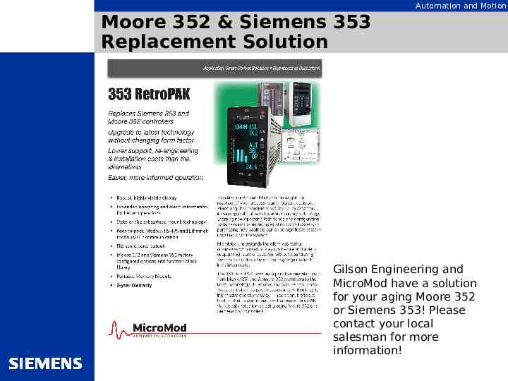
Automation and Motion Moore 352 & Siemens 353 Replacement Solution Gilson Engineering and MicroMod have a solution for your aging Moore 352 or Siemens 353! Please contact your local salesman for more information!