Storage Tanks Selection and Sizing CBE 497 1 Oct


50 Slides758.00 KB
Storage Tanks Selection and Sizing CBE 497 1 Oct 02 [email protected]
Dow Chemical - LOPC LOPC stands for Loss of Primary Containment. Considerable effort goes into preventing loss of product from storage tanks and vessels. LOPC generally leads to fires and explosions with loss of life and loss of investment. LOC at Phillips in Houston in Oct 89 killed 23, injured 130 and cost over 750 million. LOC at Union Carbide’s plant in Bhopal, India killed over 4000 people and cost UC well over 500 million. This is why LOPC is so important.
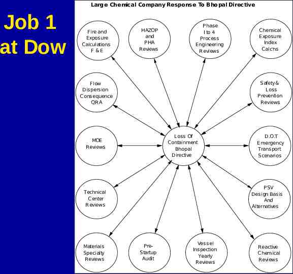
Large Chemical Company Response To Bhopal Directive Job 1 at Dow Fire and Expos ure Calculations F &E HAZOP and P HA Reviews P hase I to 4 Process Engineering R eviews Safety & Loss Prevention Reviews Flow Dispersion Cons equence QRA Loss Of Containment Bhopal Directive MOE Reviews D.O.T Emergency Transport Scenarios PSV Design Basis And Alternatives Technical Center Reviews Materials Specialty Reviews Chemical Exposure Index Calc'ns P reStartup Audit Vessel Inspection Yearly Reviews Reactive C hemical R eviews
NIOSH Data NIOSH stands for National Institute for Occupational Safety and Health. Lookup your chemical on the NIOSH Pocket Guide to Chemical Hazards. http://www.cdc.gov/niosh/npg/npg.html As soon as you know you have a certain chemical, extract the following NIOSH data:
NIOSH Exposure Limits Ca. Any substance that NIOSH considers to be an occupational carcinogen is designated by the notation – Ca. REL – Recommended Exposure Limit based on a 10 hour workday during a 40 hour work week. A ceiling REL is designated by a “C” preceding the value. The ceiling value should not be exceeded at any time.
NIOSH STEL Short term exposure limit (STEL) is a 15 minute time weighted average (TWA) exposure limit that should not be exceeded at any time during a workday.
NIOSH Gives OSHA Limits NIOSH also presents Occupational Safety and Health Act data (OSHA). OSHA uses PEL for permissible exposure limits.
NIOSH Gives ACGIH Limits The American Conference of Governmental Industrial Hygiene (ACGIH). ACGIH uses Threshold Limit Values (TLV) which are 8 hour TWA concentrations ACGIH A1 is a confirmed carcinogen. ACGIH A2 is a suspected carcinogen. ST is a 15 minute TWA value for a STEL.
NIOSH IDLH IDLH stands for Immediately dangerous to life and health. IDLH represents the maximum concentration from which, in the case of respirator failure, one could escape within 30 minutes without a respirator and without experiencing any escapeimpairing or irreversible effects.
NIOSH Flammability LEL Lower Explosive Limit aka LFL for Lower Flammable Limit in vol% in air at room temperature. UEL Upper Explosive Limit aka UFL for Upper flammable Limit in vol% in air at room temperature. Flash Point (Fl.P.) using either closed cup (cc) or open cup (op) methods.
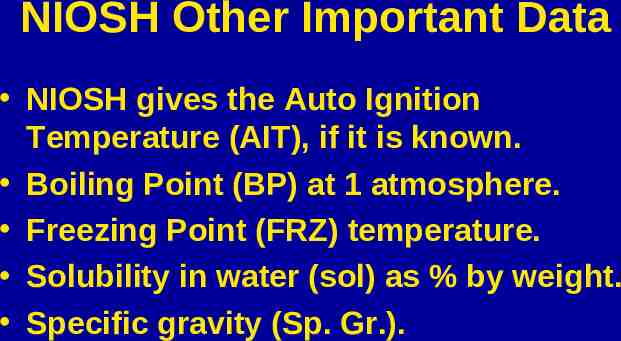
NIOSH Other Important Data NIOSH gives the Auto Ignition Temperature (AIT), if it is known. Boiling Point (BP) at 1 atmosphere. Freezing Point (FRZ) temperature. Solubility in water (sol) as % by weight. Specific gravity (Sp. Gr.).
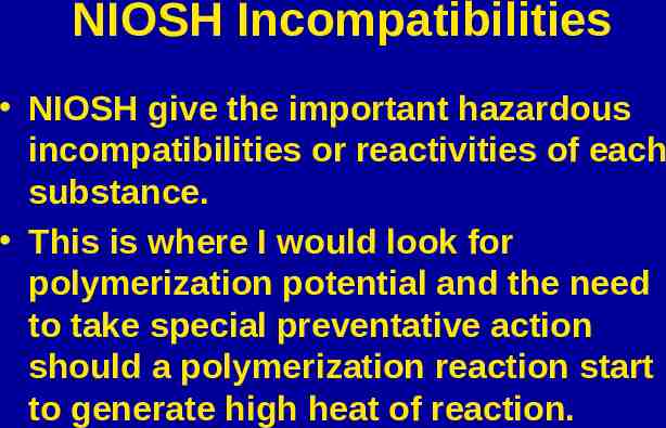
NIOSH Incompatibilities NIOSH give the important hazardous incompatibilities or reactivities of each substance. This is where I would look for polymerization potential and the need to take special preventative action should a polymerization reaction start to generate high heat of reaction.
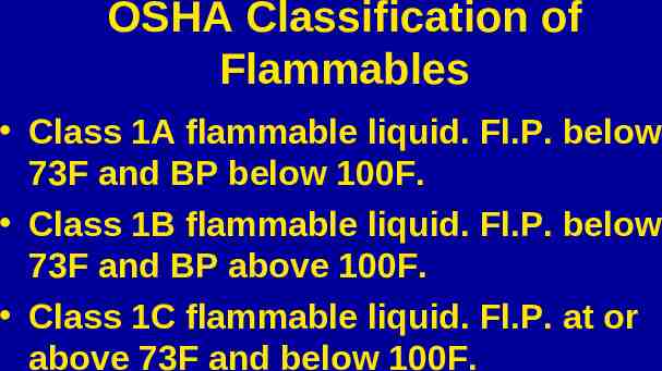
OSHA Classification of Flammables Class 1A flammable liquid. Fl.P. below 73F and BP below 100F. Class 1B flammable liquid. Fl.P. below 73F and BP above 100F. Class 1C flammable liquid. Fl.P. at or above 73F and below 100F.
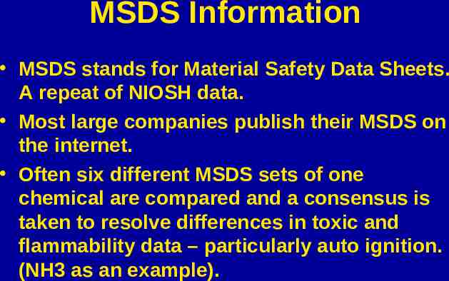
MSDS Information MSDS stands for Material Safety Data Sheets. A repeat of NIOSH data. Most large companies publish their MSDS on the internet. Often six different MSDS sets of one chemical are compared and a consensus is taken to resolve differences in toxic and flammability data – particularly auto ignition. (NH3 as an example).
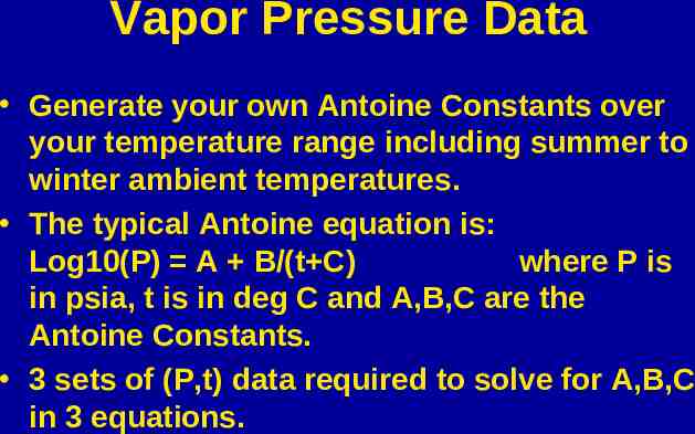
Vapor Pressure Data Generate your own Antoine Constants over your temperature range including summer to winter ambient temperatures. The typical Antoine equation is: Log10(P) A B/(t C) where P is in psia, t is in deg C and A,B,C are the Antoine Constants. 3 sets of (P,t) data required to solve for A,B,C in 3 equations.
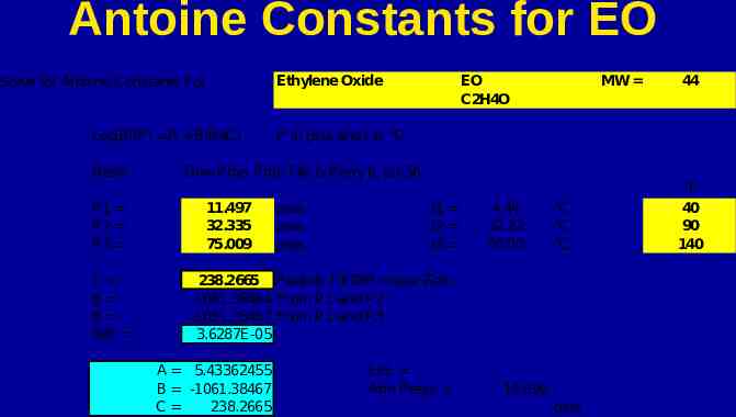
Antoine Constants for EO Solve for Antoine Constants For Log10(P) A B/(t C) Basis P1 P2 P3 C B B Diff Ethylene Oxide EO C2H4O MW 44 P in psia and t in C Dow Phys Prop File & Perry 6, p3-56 11.497 32.335 75.009 psia psia psia t1 t2 t3 4.44 32.22 60.00 C C C 238.2665 Perturb Till Diff near Zero -1061.38464 From P1 and P2 -1061.38467 From P1 and P3 3.6287E-05 A 5.43362455 B -1061.38467 C 238.2665 LEL Atm Press 14.696 psia F 40 90 140
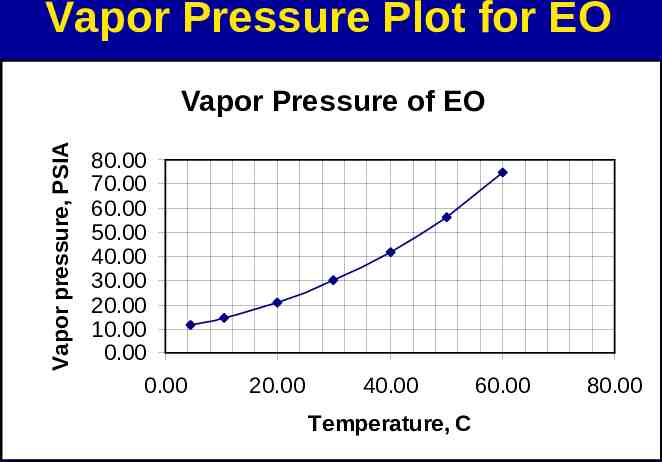
Vapor Pressure Plot for EO Vapor pressure, PSIA Vapor Pressure of EO 80.00 70.00 60.00 50.00 40.00 30.00 20.00 10.00 0.00 0.00 20.00 40.00 Temperature, C 60.00 80.00
Vapor Pressure Info Look to see where VP is at lowest ambient temperature. If the VP is below atmospheric pressure of 14.7 psia, and if the chemical is a flammable chemical, air will leak into the vessel creating an extremely hazardous situation. Static electricity created by falling liquid into the vessel can set off an explosion.
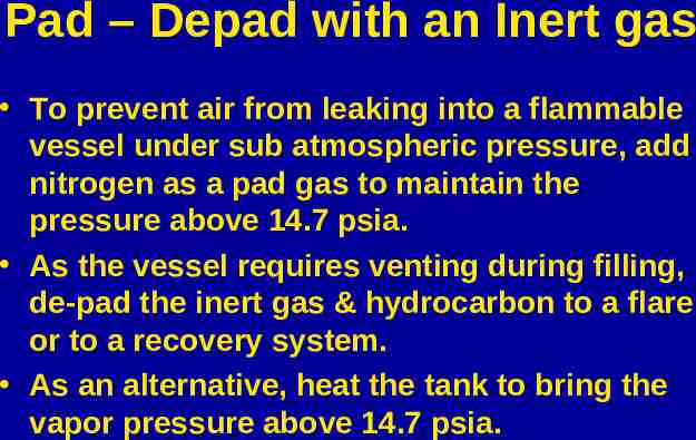
Pad – Depad with an Inert gas To prevent air from leaking into a flammable vessel under sub atmospheric pressure, add nitrogen as a pad gas to maintain the pressure above 14.7 psia. As the vessel requires venting during filling, de-pad the inert gas & hydrocarbon to a flare or to a recovery system. As an alternative, heat the tank to bring the vapor pressure above 14.7 psia.
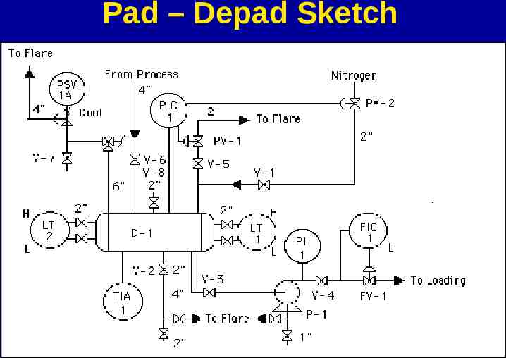
Pad – Depad Sketch
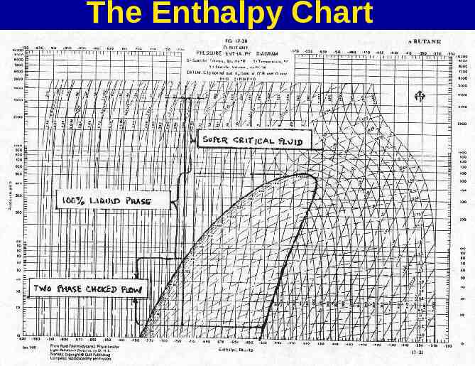
The Enthalpy Chart
The Enthalpy Chart Cont’d It provides a roadmap for your process. Try to find an enthalpy chart for your single component chemicals. If one is not available, you can construct your own from HYSIS. The enthalpy chart tells you about the need for pre-heaters, vaporizers, superheaters, knock-out pots, pumps, compressors.
MIACC or RMP? Check to see if your chemical is listed on the Major Industrial Accident Coordinating Committee List. Check to see if your chemical is listed on the U.S. Risk Management Plan List. These lists tell you whether or not you need to take toxic or flammable preventative measures in your design.
U.S. RMP The U.S. RMP method is now favored in Canada over the CDN MIACC method. If your chemical is on the list and if your quantity exceeds the specified threshold quantity, you must run the RMP program to determine the environmental impact on the public and file the results with the EPA. The EPA will approve your plant design if you have developed a suitable emergency response plan with the public.
RMP Computer Program RMP Worst Case Scenario tells you the impact distance from your storage tank to the public for either a toxic or flammable chemical. Free download at http://www.epa.gov/ceppo/tools/rmp-comp/rmp-com p.html Download it on to your hard disc. It’s very simple to use. If you don’t know your storage quantity yet, run the threshold quantity to see how big a problem you may have. You may decide to store less.
Design Tools Needed The Ideal Gas Law, P1V1/T1 P2V2/T2 Dalton’s law of Additive Pressure. Dew Point calculation. Bubble Point calculation. Flash % calculation. Equation of state PV (Z)(n)(R)(T) The Antoine Vapor Pressure equation.
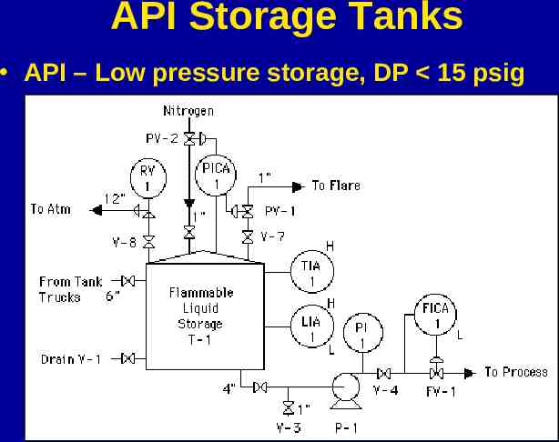
API Storage Tanks API – Low pressure storage, DP 15 psig
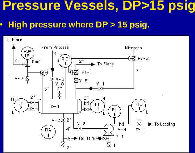
Pressure Vessels, DP 15 psig High pressure where DP 15 psig.
Codes for API Tanks API-12B – bolted tanks API-12D – field welded tanks API-12F – shop welded tanks API-620 – large welded, low pressure tanks API-650 – welded steel tanks for oil storage.
Codes for Pressure Vessels ASME VIII - Pressure Vessel Code B51-M1981 – Canadian Standards Association – Code for the Construction and Inspection of Boilers and Pressure Vessels.
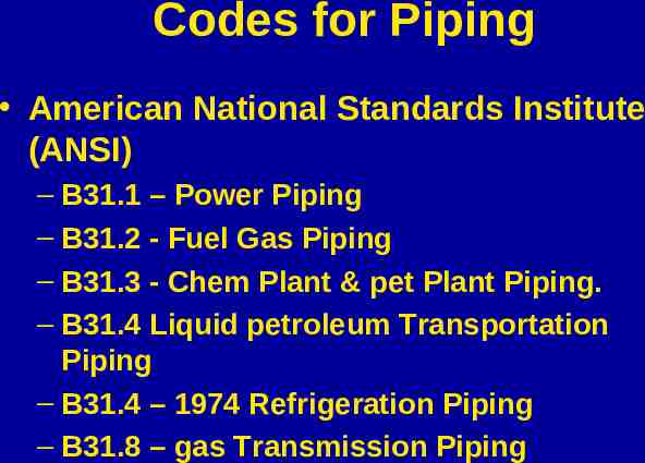
Codes for Piping American National Standards Institute (ANSI) – B31.1 – Power Piping – B31.2 - Fuel Gas Piping – B31.3 - Chem Plant & pet Plant Piping. – B31.4 Liquid petroleum Transportation Piping – B31.4 – 1974 Refrigeration Piping – B31.8 – gas Transmission Piping
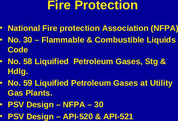
Fire Protection National Fire protection Association (NFPA) No. 30 – Flammable & Combustible Liquids Code No. 58 Liquified Petroleum Gases, Stg & Hdlg. No. 59 Liquified Petroleum Gases at Utility Gas Plants. PSV Design – NFPA – 30 PSV Design – API-520 & API-521
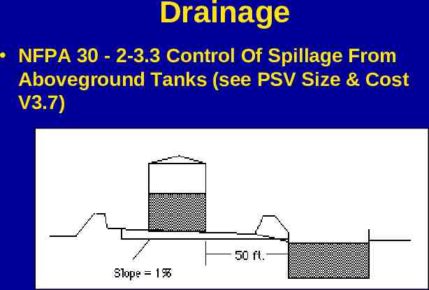
Drainage NFPA 30 - 2-3.3 Control Of Spillage From Aboveground Tanks (see PSV Size & Cost V3.7)
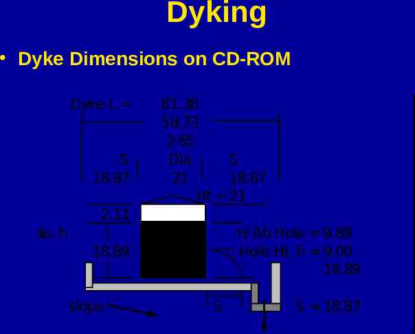
Dyking Dyke Dimensions on CD-ROM Dyke L S 18.87 61.38 58.73 2.65 Dia S 21 18.87 Ht 21 2.11 above grade, h H Ab Hole 9.89 Hole Ht, h 9.00 18.89 18.89 slope S S 18.87
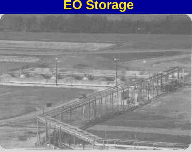
EO Storage
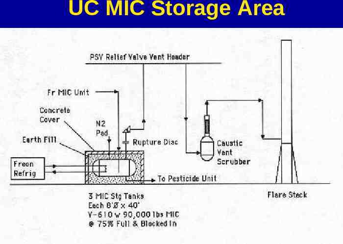
UC MIC Storage Area
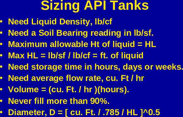
Sizing API Tanks Need Liquid Density, lb/cf Need a Soil Bearing reading in lb/sf. Maximum allowable Ht of liquid HL Max HL lb/sf / lb/cf ft. of liquid Need storage time in hours, days or weeks. Need average flow rate, cu. Ft / hr Volume (cu. Ft. / hr )(hours). Never fill more than 90%. Diameter, D [ cu. Ft. / .785 / HL ] 0.5
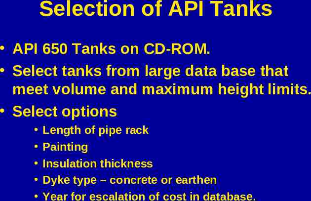
Selection of API Tanks API 650 Tanks on CD-ROM. Select tanks from large data base that meet volume and maximum height limits. Select options Length of pipe rack Painting Insulation thickness Dyke type – concrete or earthen Year for escalation of cost in database.
Calculate Heat Loss Heat Loss From Vessels on CD-ROM May have to add re-circulating pumps and heat exchangers. Basic goal is to save energy at DCFRRAT of 20% or better.
Determine Breathing Losses Storage Tank Venting folder on CD-ROM Read Design Methods for Storage Tank Venting. BLOSS program on CR-ROM for breathing losses due to ambient temperature changes and pump in / pump out changes. Make changes in process to lower losses.
Sizing Pressure Vessels Pressure Vessels V1.5 on CD-ROM Need volume, cf, by (lb/hr)(hrs) / (lb/cf) Use a safety factor of 40%. Select diameter, D, and length, L, so that L/D 4 to 5 or thereabouts. Select Design Pressure, DP, and Design Temperature, DT, to safely cover all upset conditions.
Sizing PV Cont’d Select Corrosion Allowance – ca, usually 1/16 inch for inside. May have to allow 1/16 inch for outside corrosive atmospheres – near Cl2 plant. Select materials from data base. Select Joint Efficiency, E, 0.85 or 1.0 Select flange rating 150 lb, 300 lb or ?
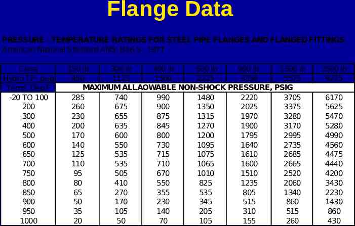
Flange Data PRESSURE - TEMPERATURE RATINGS FOR STEEL PIPE FLANGES AND FLANGED FITTINGS American National Standard ANSI B16.5 - 1977 Class Hydro TP, psig Temp, Deg F -20 TO 100 200 300 400 500 600 650 700 750 800 850 900 950 1000 150 lb 300 lb 400 lb 600 lb 900 lb 1500 lb 450 1125 1500 2225 3350 5575 MAXIMUM ALLAOWABLE NON-SHOCK PRESSURE, PSIG 285 740 990 1480 2220 3705 260 675 900 1350 2025 3375 230 655 875 1315 1970 3280 200 635 845 1270 1900 3170 170 600 800 1200 1795 2995 140 550 730 1095 1640 2735 125 535 715 1075 1610 2685 110 535 710 1065 1600 2665 95 505 670 1010 1510 2520 80 410 550 825 1235 2060 65 270 355 535 805 1340 50 170 230 345 515 860 35 105 140 205 310 515 20 50 70 105 155 260 2500 lb 9275 6170 5625 5470 5280 4990 4560 4475 4440 4200 3430 2230 1430 860 430
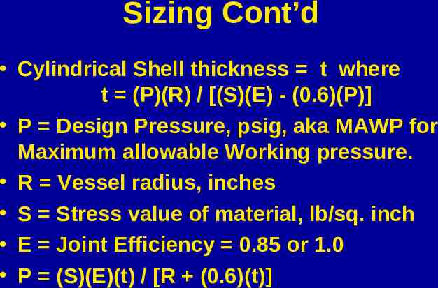
Sizing Cont’d Cylindrical Shell thickness t where t (P)(R) / [(S)(E) - (0.6)(P)] P Design Pressure, psig, aka MAWP for Maximum allowable Working pressure. R Vessel radius, inches S Stress value of material, lb/sq. inch E Joint Efficiency 0.85 or 1.0 P (S)(E)(t) / [R (0.6)(t)]
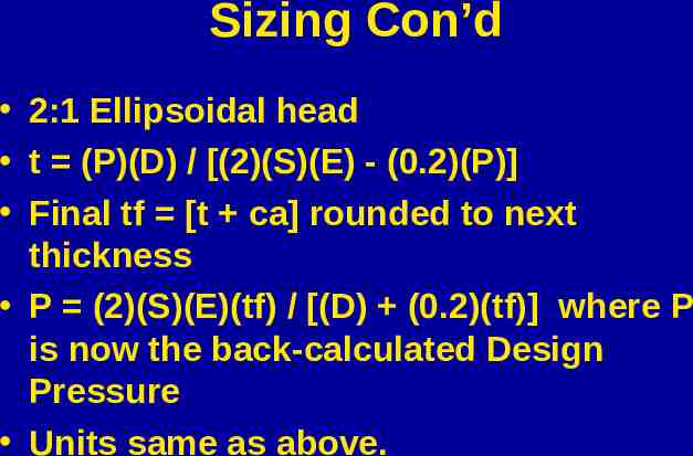
Sizing Con’d 2:1 Ellipsoidal head t (P)(D) / [(2)(S)(E) - (0.2)(P)] Final tf [t ca] rounded to next thickness P (2)(S)(E)(tf) / [(D) (0.2)(tf)] where P is now the back-calculated Design Pressure Units same as above.
Final Design Conditions Design thickness is selected on the basis of the maximum of: Longitudinal seam of cylindrical shell Head type – ellipsoidal or ASME Flange rating
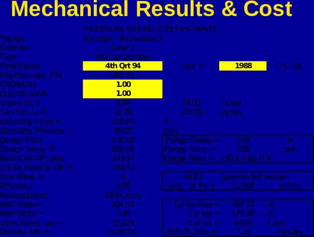
Mechanical Results & Cost Tag No. Case No. Type Time Period Fab Eqt Index, FEI CND /US Duty US CAN Vessel ID, ft Tan-Tan, L, ft Operating Temp Operating Pressure Design PSIG Design Temp, F Back Calc DP, psig 2:1 SE Head bc DP Corr Allow, in Efficiency Radiographing Mat'l Option Mat'l factor Allow Stress, psi Density, lb/ci PRESSURE VESSEL COST ESTIMATE Example - Richardson's Case 2 VKO w Demister 4th Qrt 94 1988 Year 75 - 04 361.31 1.00 1.00 4.50 54.00 inches 11.00 132.00 inches 130.00 F 95.00 psig 130.00 Flange Rating 150 lb 200.00 Flange Press 258 psig 143.87 Flange Mess 150 lb Flgs O.K. 144.53 0 -19.83 Good for full vacuum 1.00 psig at thk 0.2500 inches 100% X-ray 304 SS Cyl Sur Area 187.32 sf 2.50 Cyl Vol 174.95 cf 15,624 Cyl Vol 4,954 Litres 0.28702 BLEVE Time 7.24 minutes
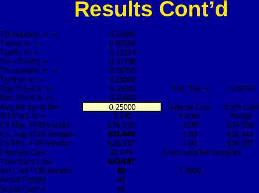
Results Cont’d Tp rounded, in. Twind, in. Tgirth, in. Tb Tw Tg Tb rounded, in. Tb final, in. Top Thk CA, in. Btm Thk CA, in. Avg thk top to btm Wt Shell, lb Cs Max, FOB Vendor Cs, Avg, FOB Vendor Cs Min., FOB Vendor Internals Cost Total Est'd Cost Act Cost FOB Vendor Actual Freight Actual Cost 0.25000 0.00584 0.11214 0.11798 0.18750 0.25000 0.25000 0.25000 0.25000 2,140 34,550 31,444 28,337 1,044 32,487 0 0 0 Min. Thk 0.18750 Special Cost Est'd Cost Factor Range 1.00 34,550 1.00 31,444 1.00 28,337 Shop Installed Demister 1.0000
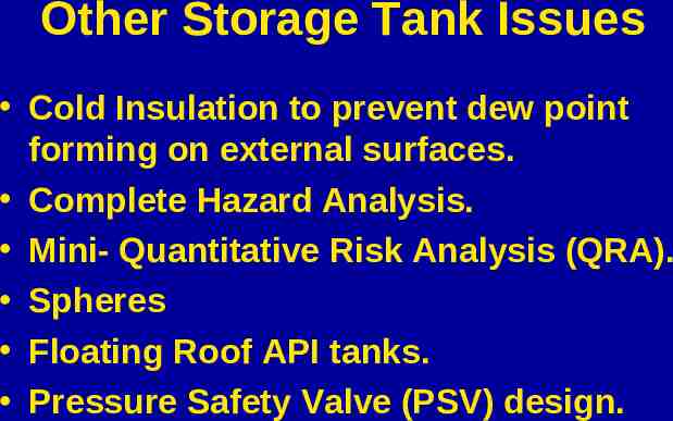
Other Storage Tank Issues Cold Insulation to prevent dew point forming on external surfaces. Complete Hazard Analysis. Mini- Quantitative Risk Analysis (QRA). Spheres Floating Roof API tanks. Pressure Safety Valve (PSV) design.
End of Presentation Good luck with your storage tank designs. Any questions? If you have questions later, email me at [email protected]