ITEC 275 Computer Networks – Switching, Routing, and WANs Week 10


97 Slides2.31 MB
ITEC 275 Computer Networks – Switching, Routing, and WANs Week 10 Robert D’Andrea Summer 2016
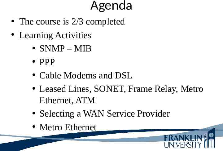
Agenda The course is 2/3 completed Learning Activities SNMP – MIB PPP Cable Modems and DSL Leased Lines, SONET, Frame Relay, Metro Ethernet, ATM Selecting a WAN Service Provider Metro Ethernet
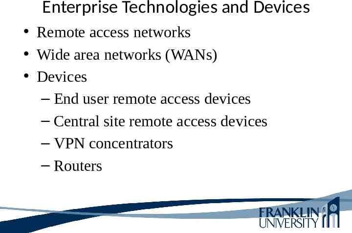
Enterprise Technologies and Devices Remote access networks Wide area networks (WANs) Devices – End user remote access devices – Central site remote access devices – VPN concentrators – Routers
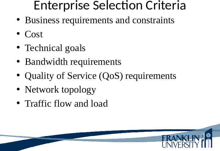
Enterprise Selection Criteria Business requirements and constraints Cost Technical goals Bandwidth requirements Quality of Service (QoS) requirements Network topology Traffic flow and load
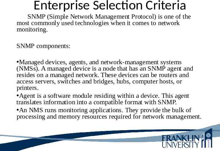
Enterprise Selection Criteria SNMP (Simple Network Management Protocol) is one of the most commonly used technologies when it comes to network monitoring. SNMP components: Managed devices, agents, and network-management systems (NMSs). A managed device is a node that has an SNMP agent and resides on a managed network. These devices can be routers and access servers, switches and bridges, hubs, computer hosts, or printers. Agent is a software module residing within a device. This agent translates information into a compatible format with SNMP. An NMS runs monitoring applications. They provide the bulk of processing and memory resources required for network management.
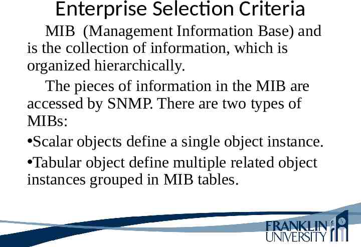
Enterprise Selection Criteria MIB (Management Information Base) and is the collection of information, which is organized hierarchically. The pieces of information in the MIB are accessed by SNMP. There are two types of MIBs: Scalar objects define a single object instance. Tabular object define multiple related object instances grouped in MIB tables.
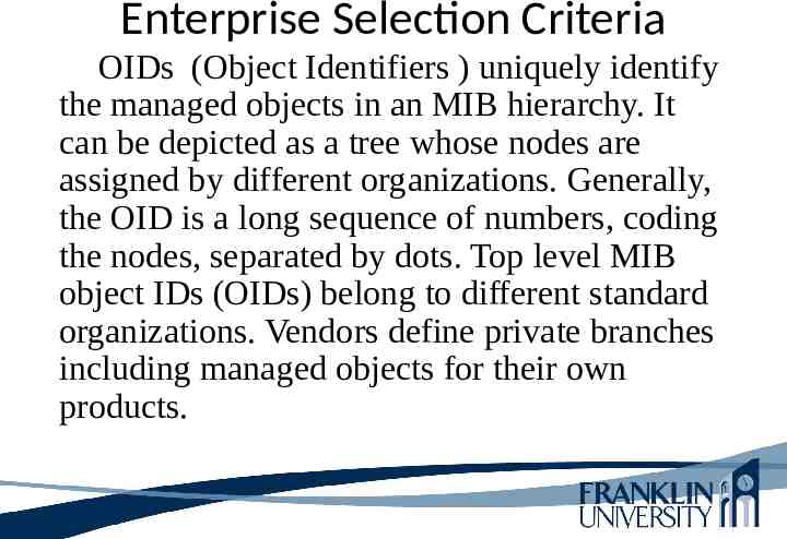
Enterprise Selection Criteria OIDs (Object Identifiers ) uniquely identify the managed objects in an MIB hierarchy. It can be depicted as a tree whose nodes are assigned by different organizations. Generally, the OID is a long sequence of numbers, coding the nodes, separated by dots. Top level MIB object IDs (OIDs) belong to different standard organizations. Vendors define private branches including managed objects for their own products.
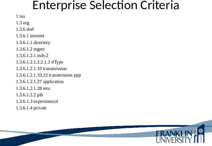
Enterprise Selection Criteria 1 iso 1.3 org 1.3.6 dod 1.3.6.1 internet 1.3.6.1.1 directory 1.3.6.1.2 mgmt 1.3.6.1.2.1 mib-2 1.3.6.1.2.1.2.2.1.3 ifType 1.3.6.1.2.1.10 transmission 1.3.6.1.2.1.10.23 transmission ppp 1.3.6.1.2.1.27 application 1.3.6.1.2.1.28 mta 1.3.6.1.2.2 pib 1.3.6.1.3 experimental 1.3.6.1.4 private
Enterprise Selection Criteria SNMP basically works from the principle that the network management systems send out a request and the managed devices return a response. The four operations are: Get, GetNext, Set, and Trap. SNMP messages consist of a header and a PDU (Protocol Data Unit). The headers consist of the SNMP version number and the community name. The community name is used as a password to increase security in SNMP.
Enterprise Selection Criteria MIBs are collections of definitions which define the properties of the managed object within the device to be managed. Examples: Objects to monitor a printer - different cartridge states and the number of printed files Objects to monitor a switch - incoming and outgoing traffic and rate of package loss or the number of packets addressed to a broadcast address.
Enterprise Selection Criteria Every managed device keeps a database of values for each of the definitions written in the MIB. So, the available data is actually not dependent on the database, but on the implementation. Each vendor of SNMP equipment has their proper section of the MIB tree structure at their disposition.
Enterprise Selection Criteria From an organizational point of view, all manageable features of all products (from each vendor) are arranged in this MIB tree structure. Each 'branch' of this tree has a number and a name, and the complete path from the top of the tree down to the point of interest forms the name of that point. This complete path is the OID, the "identifier of an object" respectively.
Enterprise Selection Criteria In summary, nodes near the top of the tree structure are general in nature. As you traverse the tree, the names get more specific until you reach the bottom, where each node represents a particular feature on a specific device or agent.
Remote Access Technologies The Point-to-Point Protocol (PPP) Integrated Services Digital Network (ISDN) Cable modems Digital Subscriber Line (DSL)
Remote Access Technologies So, what is Point Point Protocol? PPP (Point-to-Point Protocol) is a protocol for communication between two computers using a serial interface, typically a personal computer connected by phone line to a server. For example, your Internet server provider may provide you with a PPP connection so that the provider's server can respond to your requests, pass them on to the Internet, and forward your requested Internet responses back to you. PPP uses the Internet protocol (IP) (and is designed to handle others). It is sometimes considered a member of the TCP/IP suite of protocols. Relative to the Open Systems Interconnection (OSI) reference model, PPP provides layer 2 (data-link layer) service. Essentially, it packages your computer's TCP/IP packets and forwards them to the server where they can actually be put on the Internet.
Point-to-Point Protocol (PPP) PPP is used with synchronous, asynchronous, dial-up, and ISDN links PPP defines an encapsulation scheme for transporting different network-layer protocols PPP supports authentication: – Password Authentication Protocol (PAP) – Challenge Handshake Authentication Protocol (CHAP). CHAP more secure than PAP
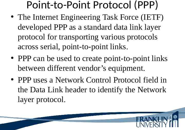
Point-to-Point Protocol (PPP) The Internet Engineering Task Force (IETF) developed PPP as a standard data link layer protocol for transporting various protocols across serial, point-to-point links. PPP can be used to create point-to-point links between different vendor’s equipment. PPP uses a Network Control Protocol field in the Data Link header to identify the Network layer protocol.
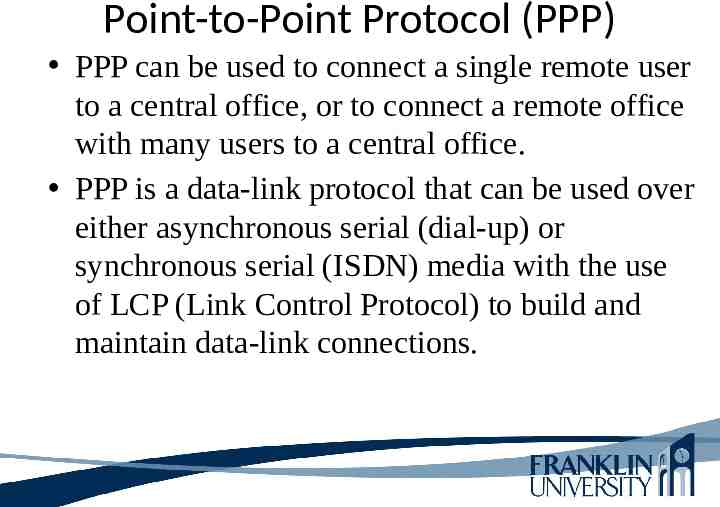
Point-to-Point Protocol (PPP) PPP can be used to connect a single remote user to a central office, or to connect a remote office with many users to a central office. PPP is a data-link protocol that can be used over either asynchronous serial (dial-up) or synchronous serial (ISDN) media with the use of LCP (Link Control Protocol) to build and maintain data-link connections.
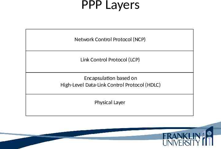
PPP Layers Network Control Protocol (NCP) Link Control Protocol (LCP) Encapsulation based on High-Level Data-Link Control Protocol (HDLC) Physical Layer
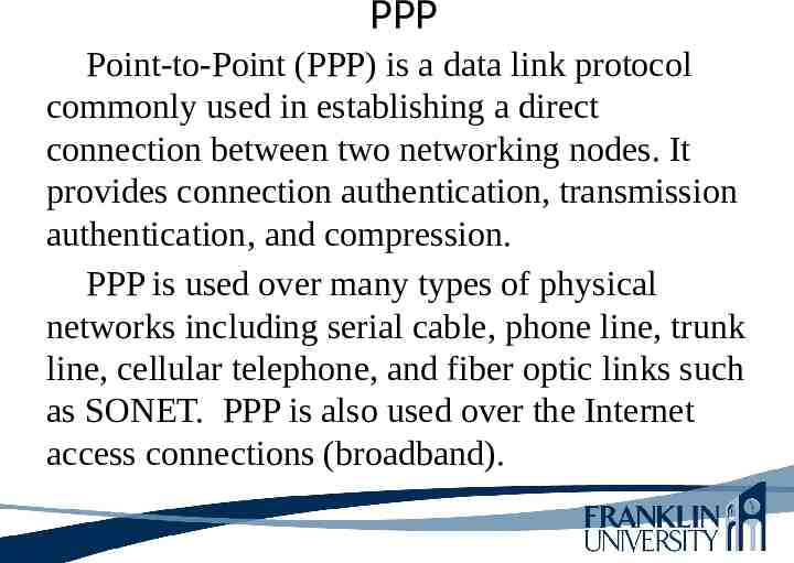
PPP Point-to-Point (PPP) is a data link protocol commonly used in establishing a direct connection between two networking nodes. It provides connection authentication, transmission authentication, and compression. PPP is used over many types of physical networks including serial cable, phone line, trunk line, cellular telephone, and fiber optic links such as SONET. PPP is also used over the Internet access connections (broadband).
PPP
PPP
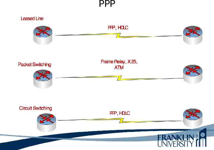
PPP Leased lines: ISP is the service provider. PPP is the protocol. The user does not want to share the wire or the expense of leasing a wire with another user. Packet Switching: Telco is the service provider. Frame Relay protocol. The user shares the service with other users to save money. Frame Relay is an alternate technology to PPP. Circuit Switching: POTS or ISDN are the service providers. PPP is the protocol. Data is sent encapsulated over the public telephone network system.
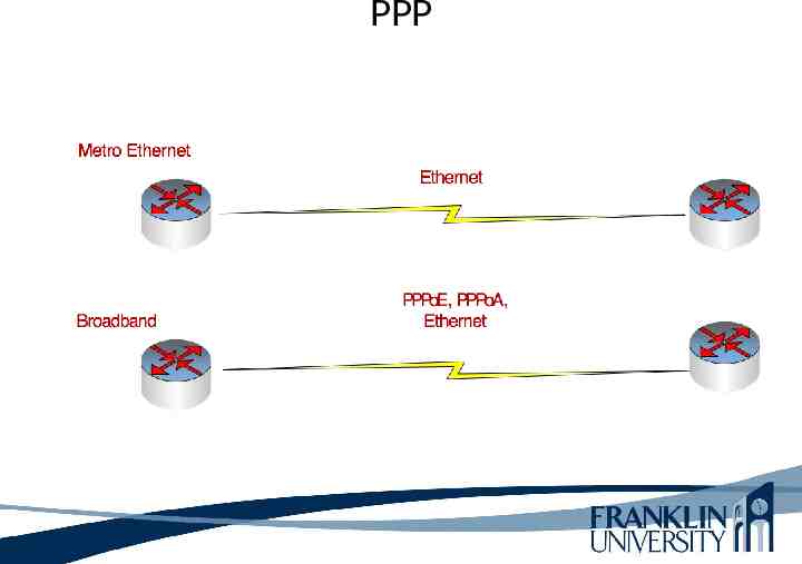
PPP Metro Ethernet: Telco is the service provider. Ethernet protocol. The user wants the data sent at a very high speed. Broadband: Telco is the service provider. PPPoE, PPPoA, Ethernet protocols.
PPP PPP encapsulation includes: 1. Line set up using LCP. The link is established during this phase. 2. Authentication, encryption and compression (optional). 2.1 Password Authentication Protocol (PAP) Avoid using PAP because it sends the password in ASCII format (clear text). 2.2 Challenge Handshake Authentication Protocol (CHAP) never sends the password, but sends a challenged handshake processes.
PPP 3. PPP carries packets from many different protocol suites using NCP. The NCP sends packets to negotiate the needed settings. Is all data encrypted? No Encryption is used to simply verify the passwords.
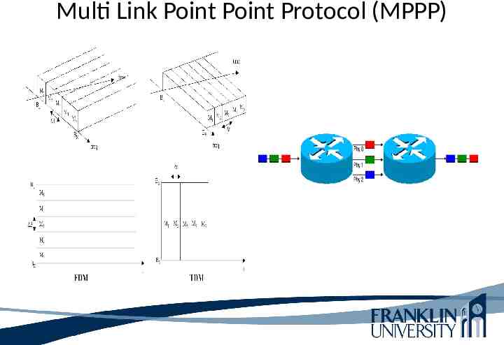
Multi Link PPP (MPPP) An ordinary dial-up modem connection to the Internet through an Internet service provider (ISP) usually uses PPP as its wide area network (WAN) data-link protocol, but there are times when the 56-Kbps speed provided by V.90 modems is insufficient. MPPP allows multiple physical dial-up links to be inverse multiplexed together to form a single high-bandwidth logical PPP connection between the dial-up client and the ISP. MPPP works by ordering the data frames from the client across the multiple PPP channels and recombs them at the ISP’s termination point, and vice versa.
Multi Link PPP (MPPP) MPPP defines protocols for splitting the data stream into PPP packets, sequencing the packets, transmitting them over separate logical data links, and then recombining them at the receiving station.
Multi Link PPP (MPPP)
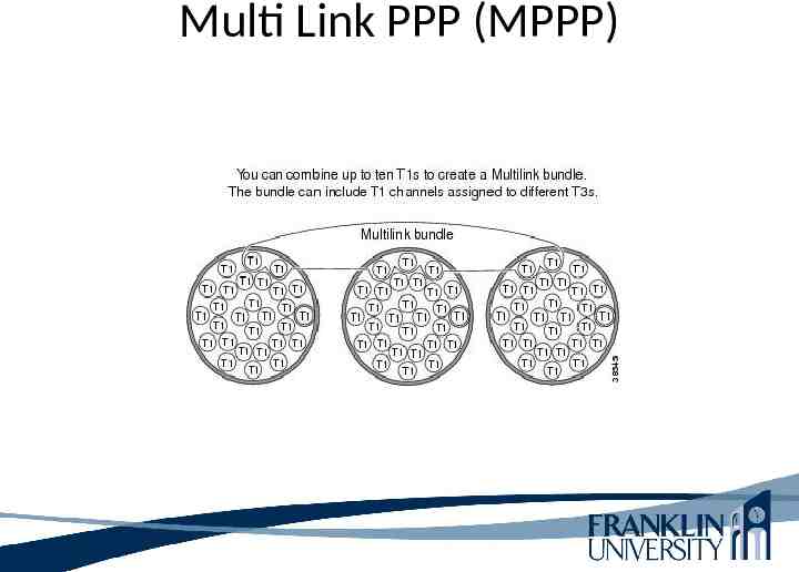
Multilink MPPP Inverse multiplexing speeds up data transmission by dividing a data stream into multiple concurrent streams that are transmitted at the same time across separate channels (such as a T-1 or E-1 lines) and are then reconstructed at the other end back into the original data stream. Just the reverse of ordinary multiplexing , which combines multiple signals into a single signal, inverse multiplexing is a technique commonly used where data in a high-speed local area network (LAN) flows back and forth into a wide area network (WAN) across the "bottleneck" of a slower line such as a T-1 (1.544 Mbps).
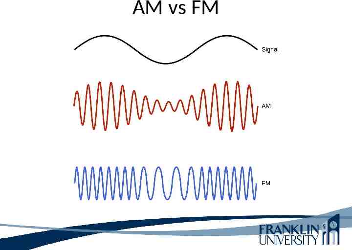
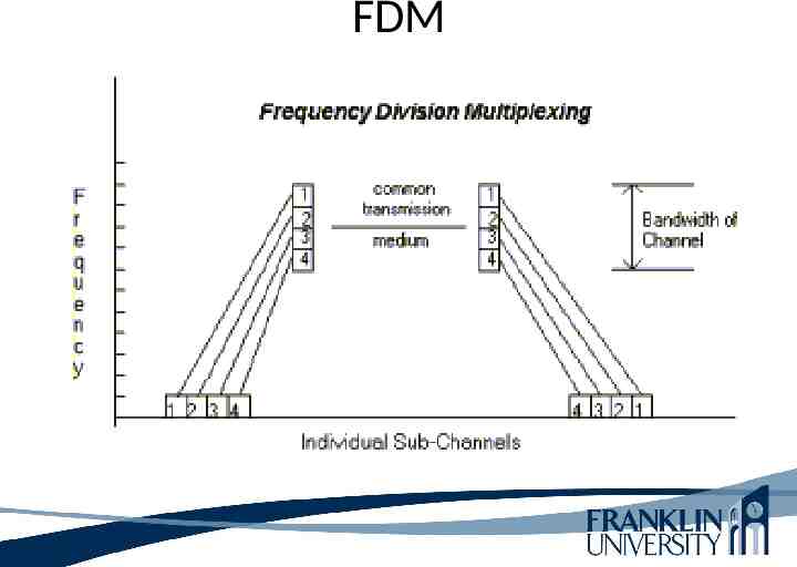
Multilink MPPP Various multiplexing methods are possible in terms of the channel bandwidth and time, and the signal, in particular the frequency, phase or time. The two basic methods are: Frequency Division Multiplexing (FDM) is derived from Amplitude Modulation (AM) technique in which the signals occupy the same physical ‘line’ but in different frequency bands. Each signal occupies its own specific band of frequencies all the time, i.e. the messages share the channel bandwidth.
AM vs FM
FDM
Multi Link Point Point Protocol (MPPP)
Multi Link PPP Adds support for channel aggregation of PPP. Channel aggregation can be used for load sharing and providing extra bandwidth. With channel aggregation, a device can automatically bring up additional channels as bandwidth requirements increase. MPPP ensures that packets arrive in order at the receiving device.
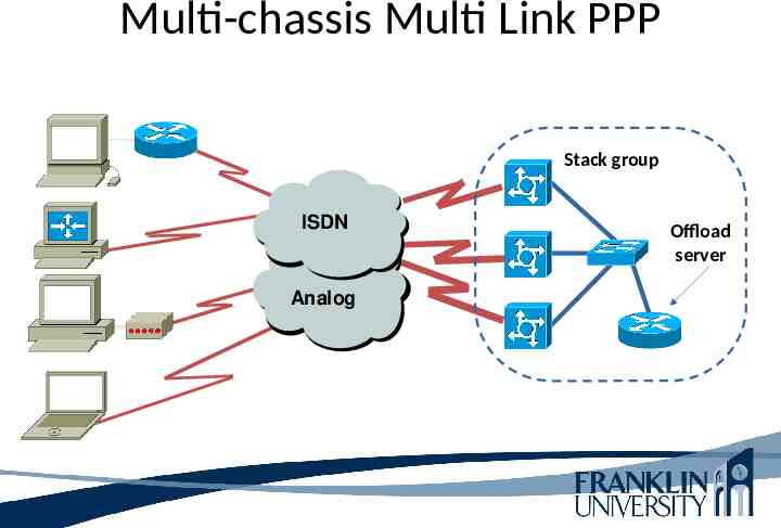
Multi-chassis MPPP Cisco’s enhancement to PPP is MPPP. MPPP allows WAN administrator to group multiple access servers into a single stack group. The user’s traffic can be split and reassembled across multiple access servers in the stack group.
Multi-chassis Multi Link PPP Stack group ISDN Analog Offload server
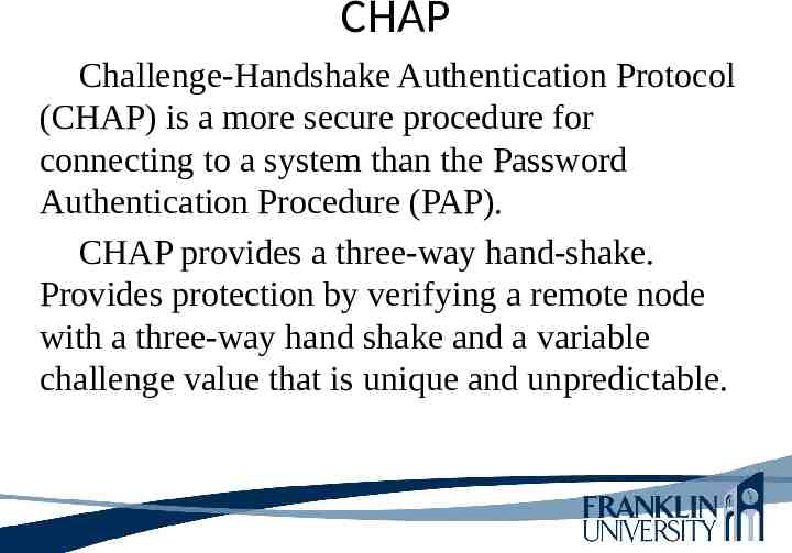
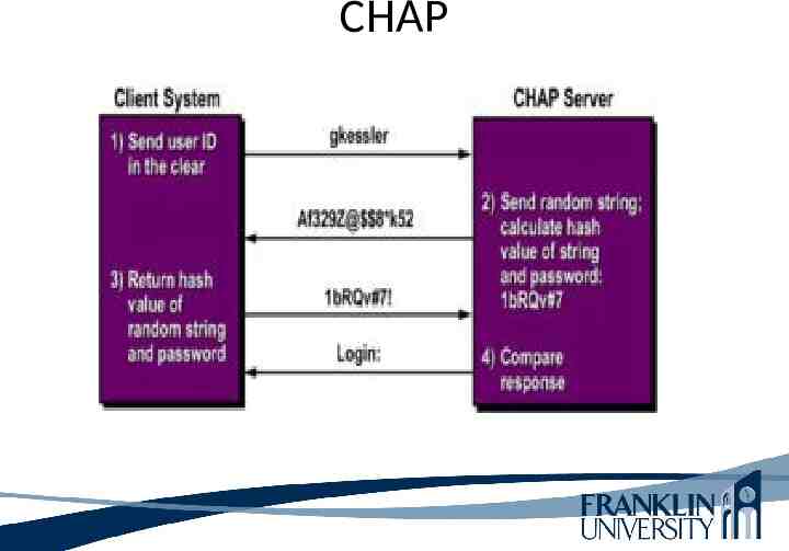
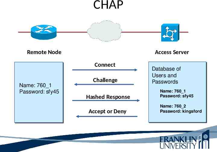
CHAP Challenge-Handshake Authentication Protocol (CHAP) is a more secure procedure for connecting to a system than the Password Authentication Procedure (PAP). CHAP provides a three-way hand-shake. Provides protection by verifying a remote node with a three-way hand shake and a variable challenge value that is unique and unpredictable.
CHAP
CHAP Remote Node Access Server Connect Name: 760 1 Password: sfy45 Challenge Hashed Response Accept or Deny Database of Users and Passwords Name: 760 1 Password: sfy45 Name: 760 2 Password: kingsford
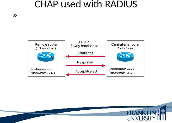
CHAP used with RADIUS »
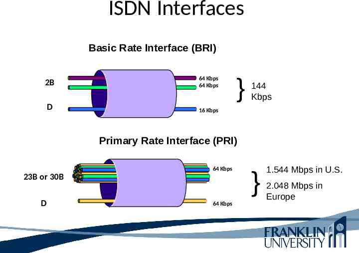
ISDN Digital data-transport service offered by regional telephone carriers (Telcos). Circuit-switched service that carries voice and data. ISDN is a set of digital services that transmits voice and data over existing phone lines. Cost-effective remote-access solution for telecommuters and remote offices – Cost of an ISDN circuit is usually based on a monthly fee plus usage time Good choice as a backup link for another type of link, for example, Frame Relay. Channel aggregation is popular with ISDN links.
ISDN Interfaces Basic Rate Interface (BRI) 2B 64 Kbps 64 Kbps D 16 Kbps } 144 Kbps Primary Rate Interface (PRI) 64 Kbps 23B or 30B D 64 Kbps } 1.544 Mbps in U.S. 2.048 Mbps in Europe
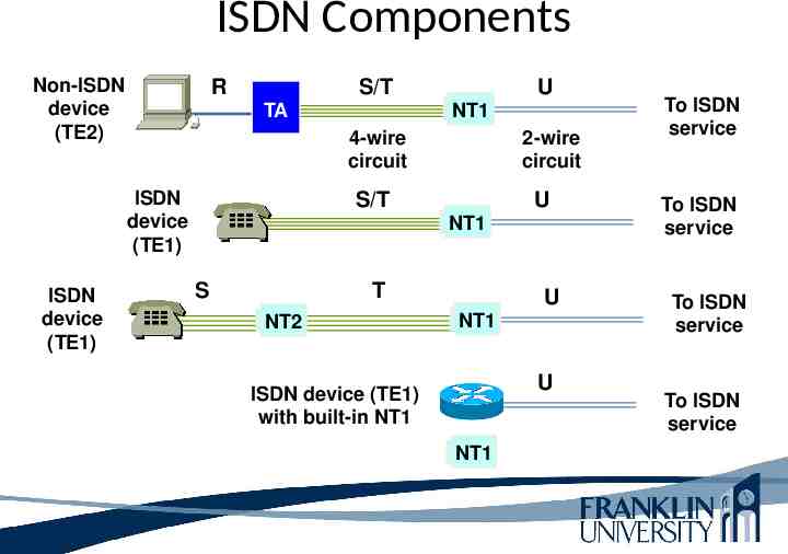
ISDN Components Non-ISDN device (TE2) R S/T NT1 TA 4-wire circuit ISDN device (TE1) ISDN device (TE1) U 2-wire circuit S/T U NT1 S T NT2 U NT1 U ISDN device (TE1) with built-in NT1 NT1 To ISDN service To ISDN service To ISDN service To ISDN service
Cable TV Service CATV (originally "community antenna television," now often "community access television") is more commonly known as "cable TV." Television programs were brought to millions of people throughout the world who were connected to a community antenna, cable TV. Today, CATV has become an increasingly popular way to interact with the World Wide Web and other new forms of multimedia information and entertainment services.
Cable TV Service Operates over the coax cable used by cable TV providers Much faster than analog modems, and usually much faster than ISDN (depending on how many users share the cable) – 25 to 50 Mbps downstream from the head end – 2 to 3 Mbps upstream from end users Standard Data Over Cable Service Interface Specification (DOCSIS)
Cable TV Service Coax Cable does not require dial-up. Cable modem operates more like a LAN. Cable-network providers offer hybrid fiber/coax (HFC) systems that connect CATV networks to the service provider’s high-speed fiber-optic network. HFC systems allow connections of home PCs and small LANs to high-speed access to the Internet or to a private network using VPN.
Cable TV Service CATV (Cable Modem Termination System) provides high-speed connectivity for cable modems. Cable modem solution for remote users or remote offices is the sharing a single cable and the types of applications they use.
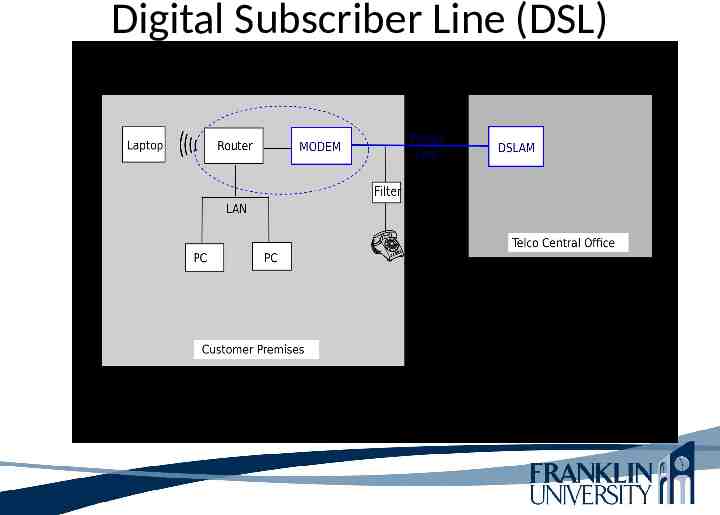
Digital Subscriber Line (DSL) High-speed digital data traffic over ordinary telephone wires. Sophisticated modulation schemes mean higher speeds than ISDN. – Speeds range from 1.544 to 9 Mbps Actual bandwidth depends on type of DSL service, DSL modem, and many physical-layer factors. Symmetric communication (SDSL) traffic flow travels at the same speed up to 1.544 Mbps. Asymmetric DSL (ADSL) very popular – Downstream faster than upstream
Digital Subscriber Line (DSL)
PPP and ADSL Asymmetric DSL (ADSL) uses two popular PPP implementations. 1. PPP and ATM (PPPoA) the CPE acts as an Ethernet-to-WAN router and the PPP session is established between the CPE and Layer 3 access concentrator in the service provider’s network. 2. PPP and Ethernet (PPPoE) the CPE acts as an Ethernet-to-WAN bridge.
PPP and ADSL PPP and Ethernet (PPPoE) the CPE acts as an Ethernet-to-WAN bridge. The client initiates a PPP session by encapsulating PPP frames in MAC frames and then bridging the frames over ATM/DSL to a gateway router at the service provider. From that point, the PPP session can be established, authenticated, and achieved. The client receives its IP address from the service provider, using PPP negotiation.
Provisioning WAN Bandwidth A critical network design is considering capacity requirements. Selecting the right amount of capacity for current and future needs. Provisioning requires an analysis of traffic flows, and analysis of scalability goals.
WAN Technologies Leased lines Synchronous Optical Network (SONET) Frame Relay Asynchronous Transfer Mode (ATM)
Leased Lines Dedicated digital, copper circuits that a customer leases from a carrier for a predetermined amount of time, usually for months or years. Speeds range from 64 Kbps to 45 Mbps. Enterprises use leased lines for both voice and data traffic.
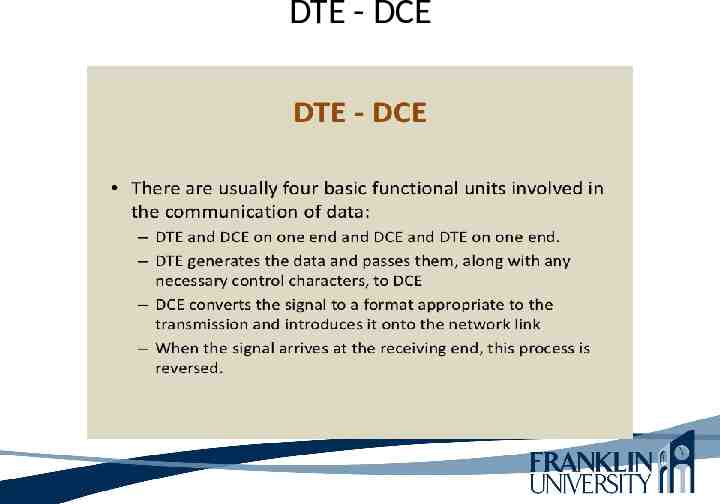
Leased Lines Dedicated connection or Point-to-Point connection. Pre-established WAN communications path from the Customer Premise Equipment (CPE) , through the Data Communications Equipment (DCE) switch, to the CPE of the remote site, then allowing Data Terminal Equipment (DTE) networks to communicate at anytime with no set up procedure before transmitting data.
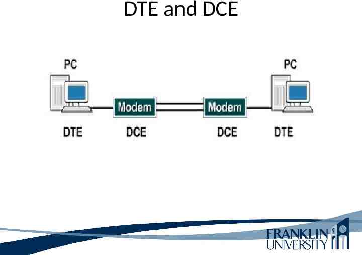
DTE and DCE The end instrument is a piece of equipment connected to the wires at the end of a telecommunication link. End instruments that relate to data terminal equipment (DTE) include printers, computers, barcode readers, automated teller machines (ATMs) and the console ports of routers.
DTE and DCE The data communication(s) equipment (DCE) is a device that sits between the DTE and a data transmission circuit. The DCE performs functions such as signal conversion, line clocking, and coding. The DTE/DCE classification was introduced by IBM.
DTE and DCE
DTE - DCE
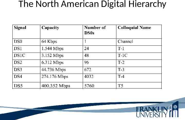
Digital Signal (DS) A channel in the NADH (North American Digital Hierarchy) is called a digital signal (DS). Digital signals are multiplexed together to form high-speed WAN circuits. DS-1 and DS-3 are the most commonly used capacities.
The North American Digital Hierarchy
Synchronous Optical Network (SONET) Synchronous Optical Network (SONET) is the American National Standards Institute standard for synchronous data transmission on optical SDH (Synchronous Digital Hierarchy) is a standard technology for synchronous data transmission on optical media.
Synchronous Optical Network (SONET) Physical-layer specification for high-speed synchronous transmission of packets or cells over fiber-optic cabling. Service providers and carriers make wide use of SONET in their internal networks. Gaining popularity within private networks.
Synchronous Optical Network (SONET) Goals of SONET and SDH 1. Define higher speeds than the ones used by the NADH. 2. Support efficient multiplexing and demultiplexing of individual signals. With SONET, it is easy to isolate one channel from a multiplexed circuit. In some instances where there are many different parts of the system are almost , but not quite, perfectly synchronised. Like the NADH and European E system, isolating one channel is more difficult.
Synchronous Optical Network (SONET) Terminating multiplexers (implemented in switches and routers) provide user access to the SONET network. Terminating multiplexers convert electrical interfaces into optical signals and multiplex multiple payloads into STS-N (Synchronous Transport Signal) signals required for optical transport.
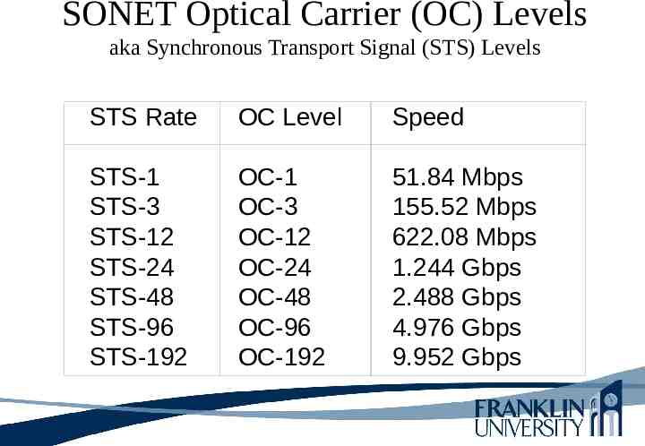
SONET Optical Carrier (OC) Levels aka Synchronous Transport Signal (STS) Levels STS Rate OC Level Speed STS-1 STS-3 STS-12 STS-24 STS-48 STS-96 STS-192 OC-1 OC-3 OC-12 OC-24 OC-48 OC-96 OC-192 51.84 Mbps 155.52 Mbps 622.08 Mbps 1.244 Gbps 2.488 Gbps 4.976 Gbps 9.952 Gbps
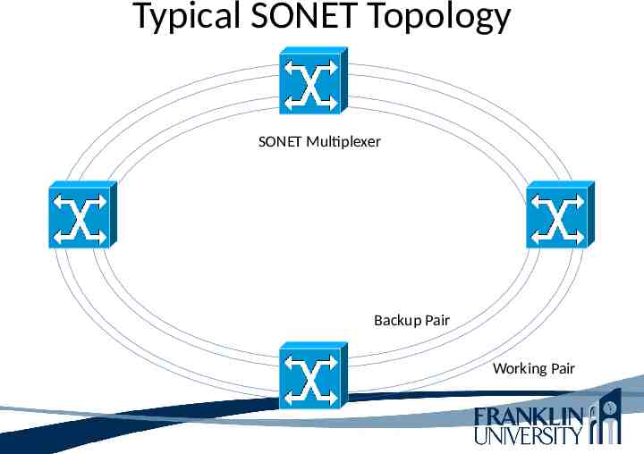
Typical SONET Topology SONET Multiplexer Backup Pair Working Pair
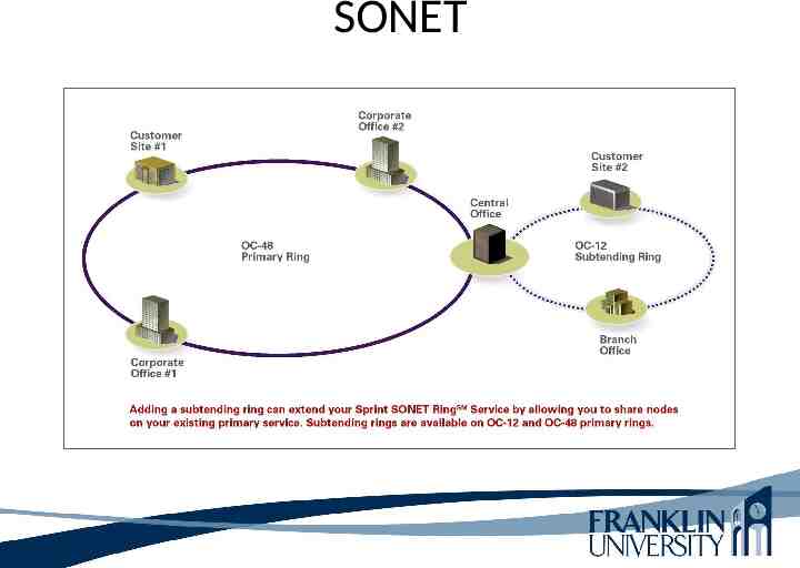
SONET
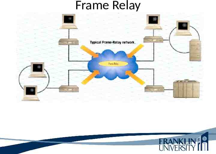
Frame Relay Frame relay is a telecommunication service designed for cost-efficient data transmission for intermittent traffic between local area networks (LANs) and between end-points in a wide area network (WAN). Frame relay puts data in a variable-size unit called a frame and leaves any necessary error correction (retransmission of data) up to the end-points, which speeds up overall data transmission. For most services, the network provides a permanent virtual circuit (PVC), which means that the customer sees a continuous, dedicated connection without having to pay for a full-time leased line, while the service provider figures out the route each frame travels to its destination and can charge based on usage.
Frame Relay Industry-standard data-link-layer protocol for transporting traffic across wide-area virtual circuits Optimized for efficiency on circuits with low error rates Attractively-priced in most parts of the world Carriers agree to forward traffic at a Committed Information Rate (CIR)
Frame Relay
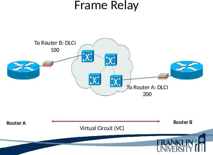
Frame Relay To Router B: DLCI 100 To Router A: DLCI 200 Router A Router B Virtual Circuit (VC)
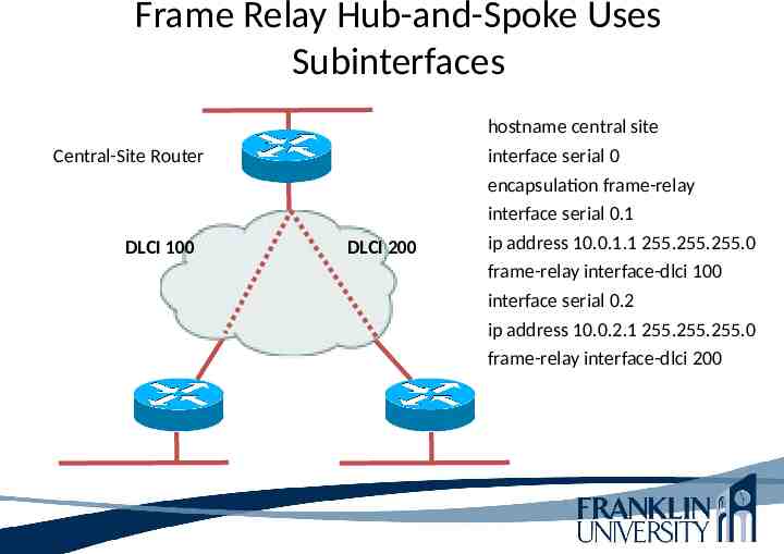
Frame Relay Hub-and-Spoke Uses Subinterfaces Central-Site Router DLCI 100 DLCI 200 hostname central site interface serial 0 encapsulation frame-relay interface serial 0.1 ip address 10.0.1.1 255.255.255.0 frame-relay interface-dlci 100 interface serial 0.2 ip address 10.0.2.1 255.255.255.0 frame-relay interface-dlci 200
Virtual Circuit What is a virtual circuit? OSI model used in example. TCP takes large blocks of information from an application and breaks them into segments. It numbers and sequences each segment so that the destination TCP protocol can put the segments back into the order the application intended. After the segments are sent, TCP (trans host) waits for an acknowledgment of the receiving end’s TCP virtual circuit session, retransmitting those that aren’t acknowledged. Before a transmission occurs, a host sends segments down the OSI model, the sender’s TCP protocol contacts the destination’s TCP protocol to establish a connection. This type of connection is considered to be connection-oriented. UDP is connectionless connection.
X.25 X.25 was optimized for excellent reliability on physical circuits with high error rates. X.25 was more complex to implement than Frame Relay. X.25 works at the physical, data link, and network layers. X.25 allows computers on different public networks (CompuServe, TCP/IP) to communicate through an intermediary computer at the network layer level.
Split Horizon A routing technique in which information about routes is prevented from exiting the router interface through which that information was received. Split horizon updates are useful in preventing routing loops. Use a sub-interface. This is a logical interface that is associated with a physical interface. The central site could have five PPP sub-interfaces defined, each communicating with one of the remotes sites. With this solution, the central site router applies the split horizon rule based on logical sub-interfaces, instead of the physical interface, and includes remote sites in the routing updates it sends out the WAN interface.
Split Horizon Split horizon can be eliminated using full mesh design with physical circuits between each site.
Asynchronous Transfer Mode (ATM) Used in service provider internal networks Gaining popularity within private networks, both WANs and sometimes LANs Supports very high bandwidth requirements – Copper cabling: 45 Mbps (T3) or more – Fiber-optic cabling: OC-192 (9.952 Gbps) and beyond, especially if technologies such as wavelength-division multiplexing (WDM) are used
ATM Provides efficient sharing of bandwidth among applications with various Quality of Service (QoS) requirements – Cell-based system inherently better for QoS than frame-based system, because frame-based system, large frames can monopolize bandwidth ATM is with a connection-oriented technology Application can specify upon connection establishment the QoS it requires Peak and minimum cell rates, cell-loss ratio, and cell-transfer delay
ATM A disadvantages of ATM is that ATM interfaces for routers and switches are expensive. ATM Video: https://www.youtube.com/watch?v 0dU1am2u1Jw https://www.youtube.com/watch?v 3VAmcN8VmIU
Ethernet over ATM ATM router interfaces are expensive Some providers allow a customer to use an Ethernet interface to access the provider’s ATM WAN May require a converter Expected to gain popularity because it has the advantages of both worlds – Easy-to-use LAN – QoS-aware WAN
Metro Ethernet What is Metro Ethernet? Metro Ethernet makes use of Carrier Ethernet technology in metropolitan area networks (MANs). Carrier Ethernet is the use of highbandwidth Ethernet technology for Internet access and for communication among business, academic and government local area networks (LANs).
Metro Ethernet Widely available in larger cities, Metro Ethernet offers efficient and scalable network services within a specific metropolitan region. These regions are frequently meshed in fiber optic networks, making Ethernet more widely available in the specified metropolitan area. Comcast Metro Ethernet offers a simple solution for users that have a complex network.
Metro Ethernet A service offered by providers and carriers that traditionally only offered WAN services Carriers offer Metro Ethernet to customers who are looking for cost-effective method to interconnect campus networks and to access the Internet. Metro Ethernet allow users to continue using 10/100 Mbps Ethernet interfaces. Supports copper and fiber optics interfaces.
Metro Ethernet Allows providers to offer bandwidth in 1Mbps increments.
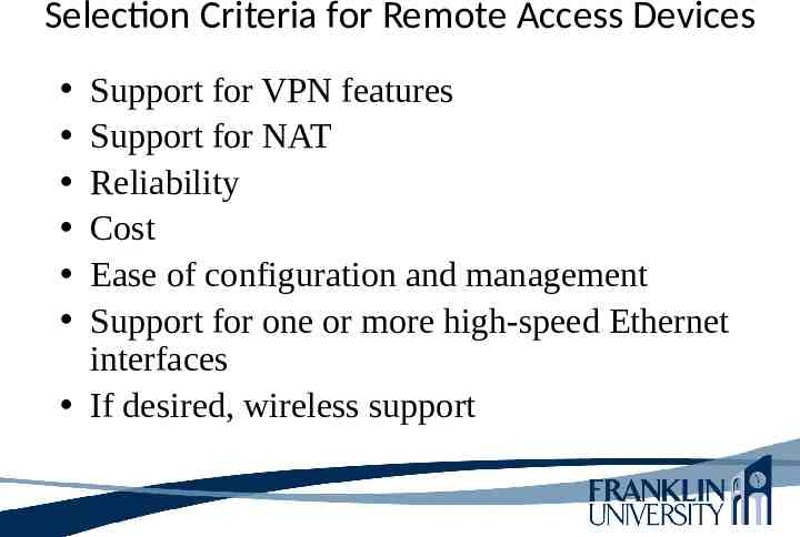
Selection Criteria for Remote Access Devices Support for VPN features Support for NAT Reliability Cost Ease of configuration and management Support for one or more high-speed Ethernet interfaces If desired, wireless support
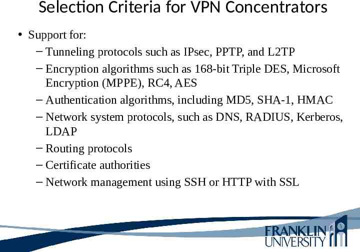
Selection Criteria for VPN Concentrators Support for: – Tunneling protocols such as IPsec, PPTP, and L2TP – Encryption algorithms such as 168-bit Triple DES, Microsoft Encryption (MPPE), RC4, AES – Authentication algorithms, including MD5, SHA-1, HMAC – Network system protocols, such as DNS, RADIUS, Kerberos, LDAP – Routing protocols – Certificate authorities – Network management using SSH or HTTP with SSL
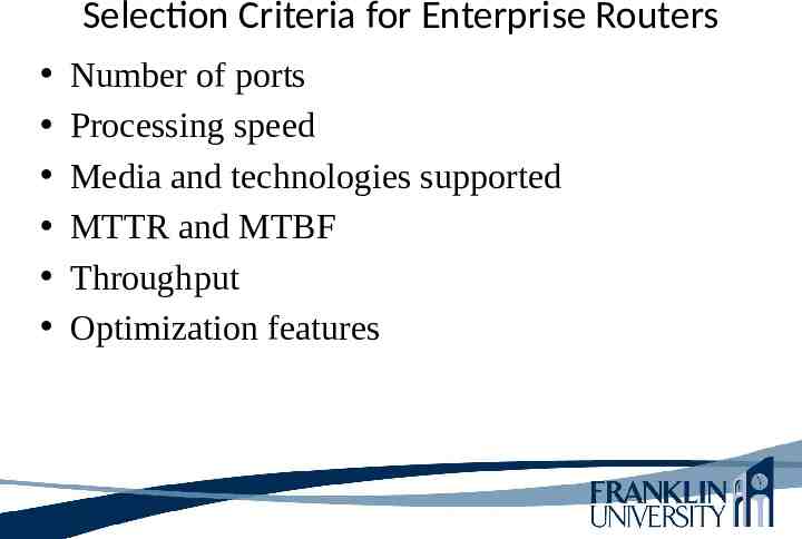
Selection Criteria for Enterprise Routers Number of ports Processing speed Media and technologies supported MTTR and MTBF Throughput Optimization features
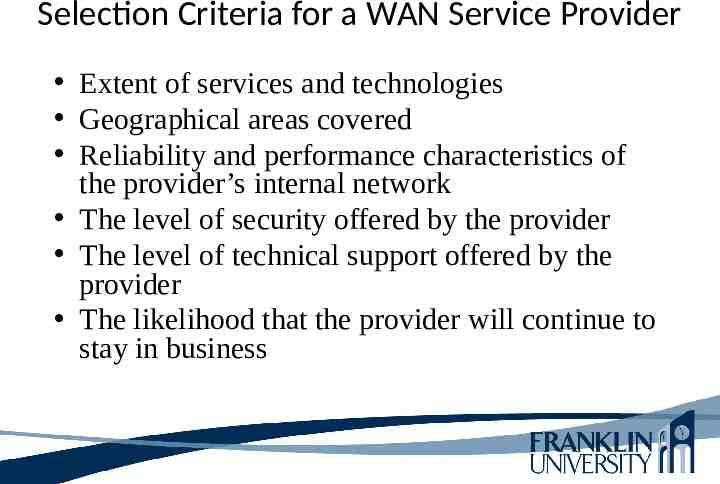
Selection Criteria for a WAN Service Provider Extent of services and technologies Geographical areas covered Reliability and performance characteristics of the provider’s internal network The level of security offered by the provider The level of technical support offered by the provider The likelihood that the provider will continue to stay in business
Selecting a Provider The provider’s willingness to work with you to meet your needs The physical routing of network links Redundancy within the network The extent to which the provider relies on other providers for redundancy The level of oversubscription on the network QoS support
Summary A major task during the physical design phase is selecting technologies and devices for enterprise networks – Remote access networks – WANs – Service providers – Devices End user remote access devices Central site remote access devices VPN concentrators Routers
Review Questions Compare and contrast technologies for supporting remote users. Compare and contrast WAN technologies. What selection criteria can you use when purchasing internetworking devices for enterprise network customers? What criteria can you use when selecting a WAN service provider?
This Week’s Outcomes PPP Frame Relay Cable Modems and DSL Leased Lines, SONET, Frame Relay, Metro Ethernet, ATM Selecting a WAN Service Provider
Due this week 11-1 – Concept questions 8
Next week Read Chapters 12 and 13 in Top-Down Network Design 12-1 – Concept questions 9 1-5-3 – Network design project – New office network FranklinLive session 13
Q&A Questions, comments, concerns?