ICTP-ITU/BDT-URSI School on Radio-Based Computer Networking

99 Slides4.26 MB
ICTP-ITU/BDT-URSI School on Radio-Based Computer Networking for Research and Training in Developing Countries The Abdus Salam International Centre for Theoretical Physics ICTP, Trieste (Italy), 7th February - 4th March 2005 Basic Antenna Theory Professor R. Struzak [email protected] Note: These are preliminary notes, intended only for distribution among the participants. Beware of misprints!
Purpose to refresh basic concepts related to the antenna physics – needed to understand better the operation and design of microwave links and systems Property of R Struzak 2
Outline Introduction Review of basic antenna types Radiation pattern, gain, polarization Equivalent circuit & radiation efficiency Smart antennas Some theory Summary Property of R Struzak 3
Quiz We use a transmitting antenna to radiate radio wave and a receiving antenna to capture the RF energy carried by the wave. Somebody told that the receiving antenna also radiates radio waves during the reception. Is it a true fact or a slip of the tongue? Property of R Struzak 4
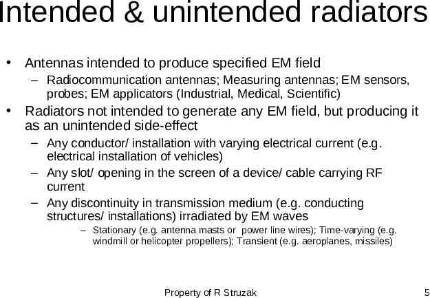
Intended & unintended radiators Antennas intended to produce specified EM field – Radiocommunication antennas; Measuring antennas; EM sensors, probes; EM applicators (Industrial, Medical, Scientific) Radiators not intended to generate any EM field, but producing it as an unintended side-effect – Any conductor/ installation with varying electrical current (e.g. electrical installation of vehicles) – Any slot/ opening in the screen of a device/ cable carrying RF current – Any discontinuity in transmission medium (e.g. conducting structures/ installations) irradiated by EM waves – Stationary (e.g. antenna masts or power line wires); Time-varying (e.g. windmill or helicopter propellers); Transient (e.g. aeroplanes, missiles) Property of R Struzak 5
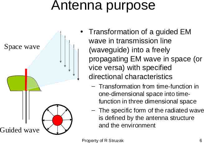
Antenna purpose Space wave Guided wave Transformation of a guided EM wave in transmission line (waveguide) into a freely propagating EM wave in space (or vice versa) with specified directional characteristics – Transformation from time-function in one-dimensional space into timefunction in three dimensional space – The specific form of the radiated wave is defined by the antenna structure and the environment Property of R Struzak 6
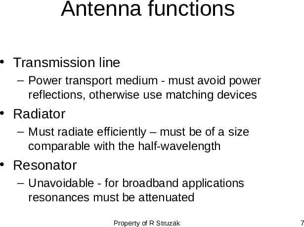
Antenna functions Transmission line – Power transport medium - must avoid power reflections, otherwise use matching devices Radiator – Must radiate efficiently – must be of a size comparable with the half-wavelength Resonator – Unavoidable - for broadband applications resonances must be attenuated Property of R Struzak 7
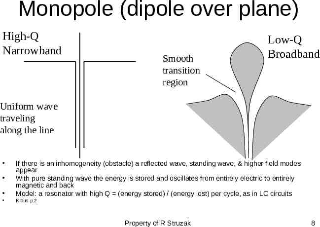
Monopole (dipole over plane) High-Q Narrowband Smooth transition region Low-Q Broadband Uniform wave traveling along the line If there is an inhomogeneity (obstacle) a reflected wave, standing wave, & higher field modes appear With pure standing wave the energy is stored and oscillates from entirely electric to entirely magnetic and back Model: a resonator with high Q (energy stored) / (energy lost) per cycle, as in LC circuits Kraus p.2 Property of R Struzak 8
Outline Introduction Review of basic antenna types Radiation pattern, gain, polarization Equivalent circuit & radiation efficiency Smart antennas Some theory Summary Property of R Struzak 9
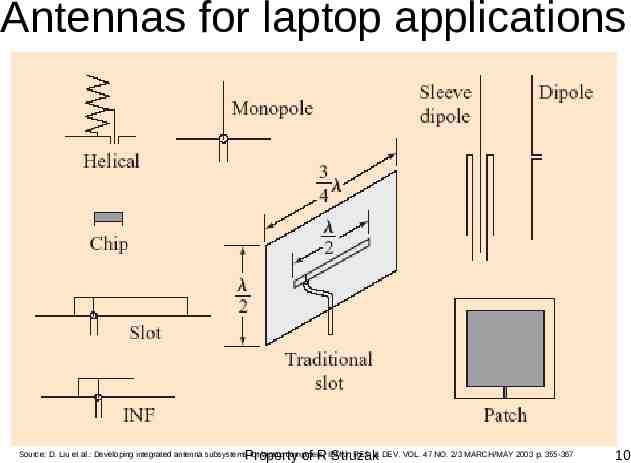
Antennas for laptop applications Property of R Struzak Source: D. Liu et al.: Developing integrated antenna subsystems for laptop computers; IBM J. RES. & DEV. VOL. 47 NO. 2/3 MARCH/MAY 2003 p. 355-367 10
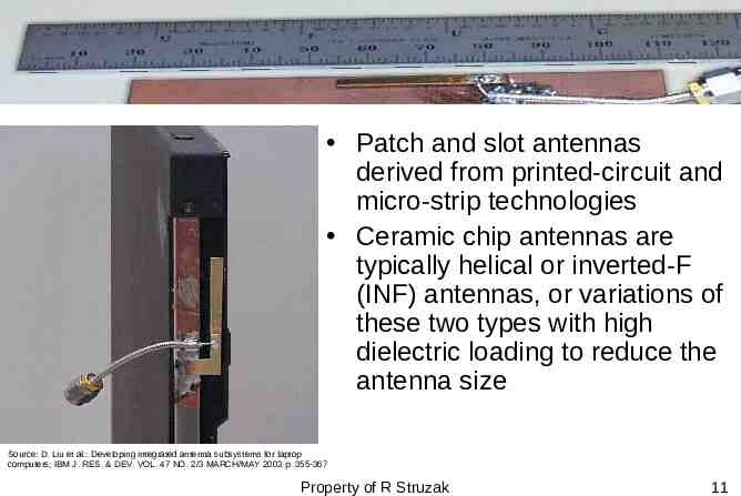
Patch and slot antennas derived from printed-circuit and micro-strip technologies Ceramic chip antennas are typically helical or inverted-F (INF) antennas, or variations of these two types with high dielectric loading to reduce the antenna size Source: D. Liu et al.: Developing integrated antenna subsystems for laptop computers; IBM J. RES. & DEV. VOL. 47 NO. 2/3 MARCH/MAY 2003 p. 355-367 Property of R Struzak 11
Slot & INF antennas Slot antenna: a slot is cut from a large (relative to the slot length) metal plate. The center conductor of the feeding coaxial cable is connected to one side of the slot, and the outside conductor of the cable - to the other side of the slot. The slot length is some ( /2) for the slot antenna and ( /4) long for the INF antenna. The slot and INF antennas behave similarly. The slot antenna can be considered as a loaded version of the INF antenna. The load is a quarter-wavelength stub, i.e. a narrowband device. When the feed point is moved to the short-circuited end of the slot (or INF) antenna, the impedance decreases. When it is moved to the slot center (or open end of the INF antenna), the impedance increases Property of R Struzak 12
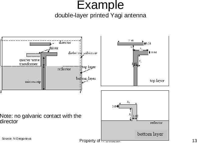
Example double-layer printed Yagi antenna Note: no galvanic contact with the director Source: N Gregorieva Property of R Struzak 13
Patch and slot antennas are – Cheap and easy to fabricate and to mount – Suited for integration – Light and mechanically robust – Have low cross-polarization – Low-profile - widely used in antenna arrays – spacecrafts, satellites, missiles, cars and other mobile applications Property of R Struzak 14
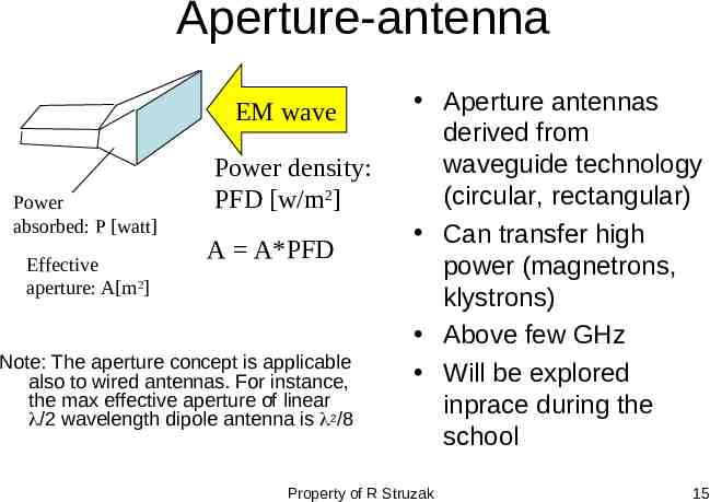
Aperture-antenna EM wave Power absorbed: P [watt] Effective aperture: A[m2] Power density: PFD [w/m2] A A*PFD Note: The aperture concept is applicable also to wired antennas. For instance, the max effective aperture of linear /2 wavelength dipole antenna is 2/8 Aperture antennas derived from waveguide technology (circular, rectangular) Can transfer high power (magnetrons, klystrons) Above few GHz Will be explored inprace during the school Property of R Struzak 15
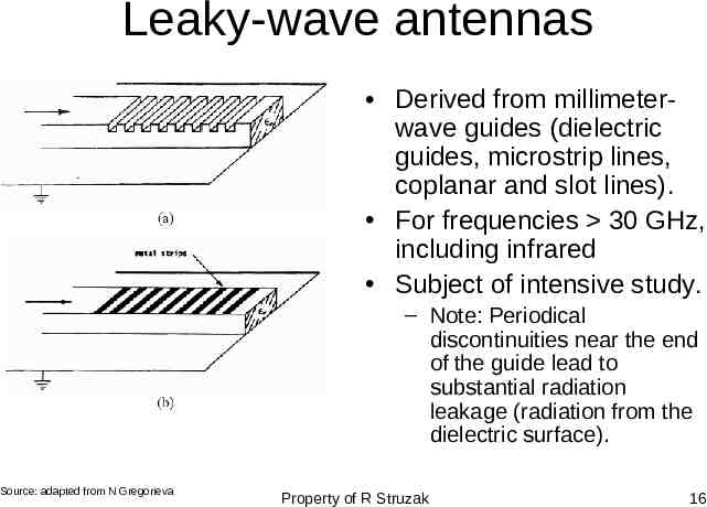
Leaky-wave antennas Derived from millimeterwave guides (dielectric guides, microstrip lines, coplanar and slot lines). For frequencies 30 GHz, including infrared Subject of intensive study. – Note: Periodical discontinuities near the end of the guide lead to substantial radiation leakage (radiation from the dielectric surface). Source: adapted from N Gregorieva Property of R Struzak 16
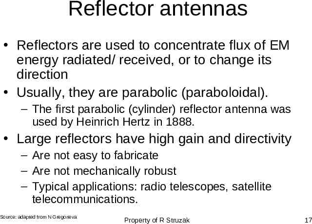
Reflector antennas Reflectors are used to concentrate flux of EM energy radiated/ received, or to change its direction Usually, they are parabolic (paraboloidal). – The first parabolic (cylinder) reflector antenna was used by Heinrich Hertz in 1888. Large reflectors have high gain and directivity – Are not easy to fabricate – Are not mechanically robust – Typical applications: radio telescopes, satellite telecommunications. Source: adapted from N Gregorieva Property of R Struzak 17
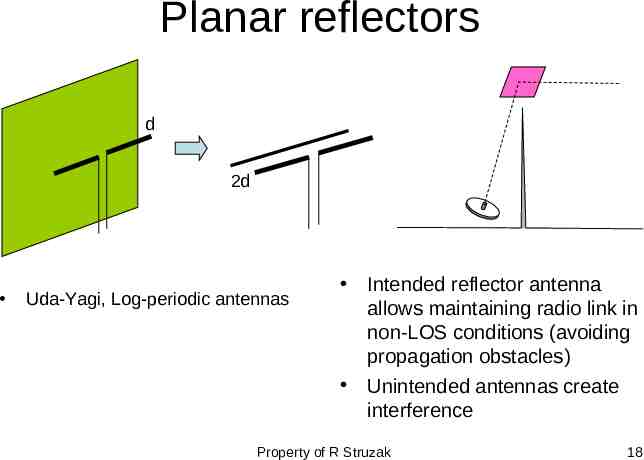
Planar reflectors d 2d Uda-Yagi, Log-periodic antennas Intended reflector antenna allows maintaining radio link in non-LOS conditions (avoiding propagation obstacles) Unintended antennas create interference Property of R Struzak 18
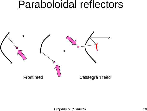
Paraboloidal reflectors Front feed Cassegrain feed Property of R Struzak 19
The largest radio telescopes Max Plank Institüt für Radioastronomie radio telescope, Effelsberg (Germany), 100-m paraboloidal reflector The Green Bank Telescope (the National Radio Astronomy Observatory) – paraboloid of aperture 100 m Source: adapted from N Gregorieva Property of R Struzak 20
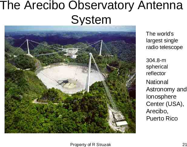
The Arecibo Observatory Antenna System The world’s largest single radio telescope 304.8-m spherical reflector National Astronomy and Ionosphere Center (USA), Arecibo, Puerto Rico Property of R Struzak 21
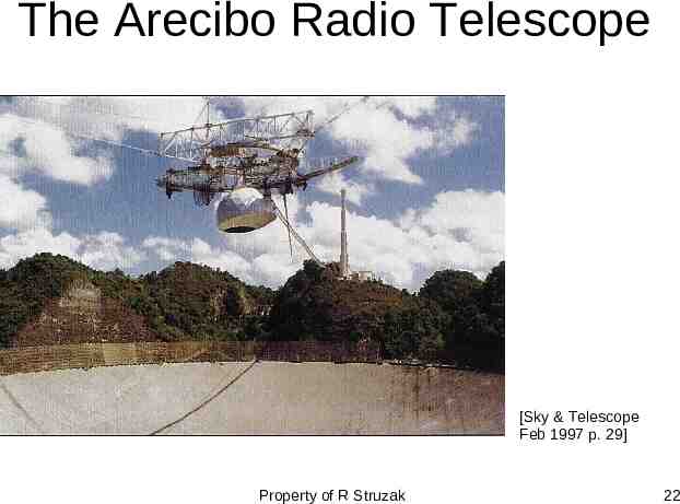
The Arecibo Radio Telescope [Sky & Telescope Feb 1997 p. 29] Property of R Struzak 22
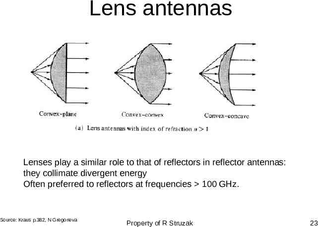
Lens antennas Lenses play a similar role to that of reflectors in reflector antennas: they collimate divergent energy Often preferred to reflectors at frequencies 100 GHz. Source: Kraus p.382, N Gregorieva Property of R Struzak 23
Outline Introduction Review of basic antenna types Radiation pattern, gain, polarization Equivalent circuit & radiation efficiency Smart antennas Some theory Summary Property of R Struzak 24
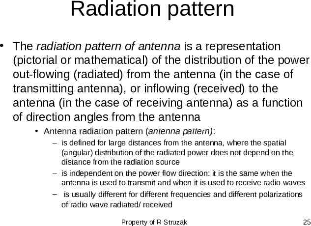
Radiation pattern The radiation pattern of antenna is a representation (pictorial or mathematical) of the distribution of the power out-flowing (radiated) from the antenna (in the case of transmitting antenna), or inflowing (received) to the antenna (in the case of receiving antenna) as a function of direction angles from the antenna Antenna radiation pattern (antenna pattern): – is defined for large distances from the antenna, where the spatial (angular) distribution of the radiated power does not depend on the distance from the radiation source – is independent on the power flow direction: it is the same when the antenna is used to transmit and when it is used to receive radio waves – is usually different for different frequencies and different polarizations of radio wave radiated/ received Property of R Struzak 25
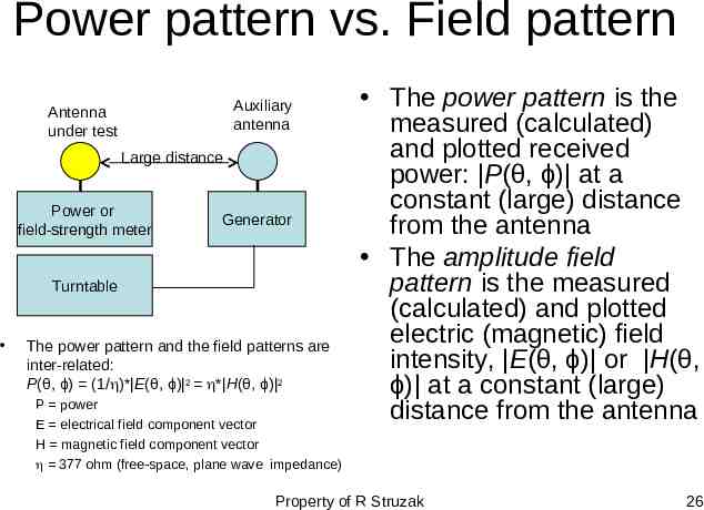
Power pattern vs. Field pattern Auxiliary antenna Antenna under test Large distance Power or field-strength meter Generator Turntable The power pattern and the field patterns are inter-related: P(θ, ϕ) (1/ )* E(θ, ϕ) 2 * H(θ, ϕ) 2 P power E electrical field component vector H magnetic field component vector 377 ohm (free-space, plane wave impedance) The power pattern is the measured (calculated) and plotted received power: P(θ, ϕ) at a constant (large) distance from the antenna The amplitude field pattern is the measured (calculated) and plotted electric (magnetic) field intensity, E(θ, ϕ) or H(θ, ϕ) at a constant (large) distance from the antenna Property of R Struzak 26
Normalized pattern Usually, the pattern describes the normalized field (power) values with respect to the maximum value. – Note: The power pattern and the amplitude field pattern are the same when computed and when plotted in dB. Property of R Struzak 27
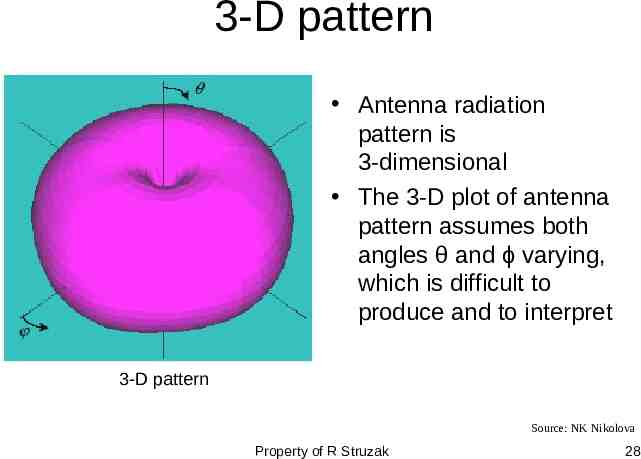
3-D pattern Antenna radiation pattern is 3-dimensional The 3-D plot of antenna pattern assumes both angles θ and ϕ varying, which is difficult to produce and to interpret 3-D pattern Source: NK Nikolova Property of R Struzak 28
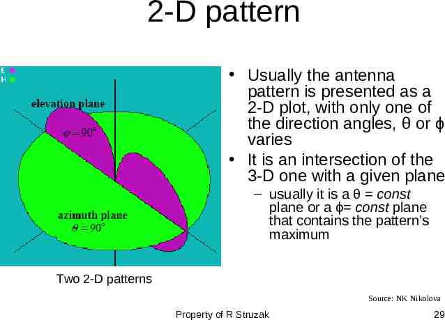
2-D pattern Usually the antenna pattern is presented as a 2-D plot, with only one of the direction angles, θ or ϕ varies It is an intersection of the 3-D one with a given plane – usually it is a θ const plane or a ϕ const plane that contains the pattern’s maximum Two 2-D patterns Source: NK Nikolova Property of R Struzak 29
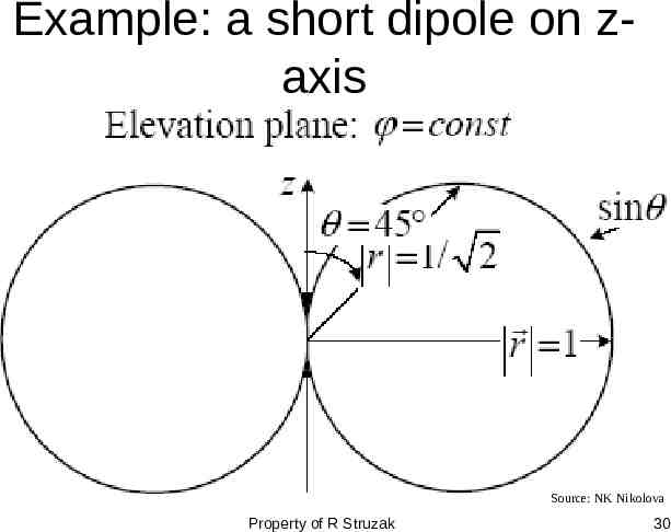
Example: a short dipole on zaxis Source: NK Nikolova Property of R Struzak 30
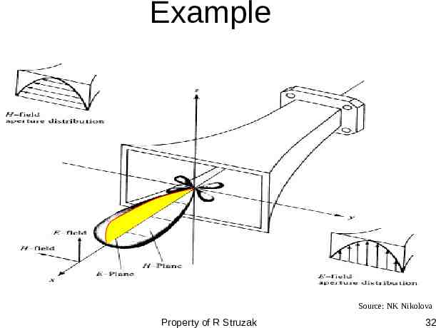
Principal patterns Principal patterns are the 2-D patterns of linearly polarized antennas, measured in 2 planes 1. the E-plane: a plane parallel to the E vector and containing the direction of maximum radiation, and 2. the H-plane: a plane parallel to the H vector, orthogonal to the E-plane, and containing the direction of maximum radiation Source: NK Nikolova Property of R Struzak 31
Example Source: NK Nikolova Property of R Struzak 32
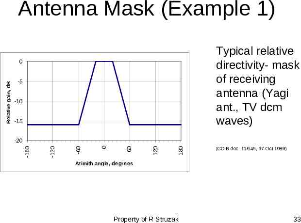
Antenna Mask (Example 1) Typical relative directivity- mask of receiving antenna (Yagi ant., TV dcm waves) -5 -10 -15 180 120 60 0 -60 -120 -20 -180 Relative gain, dB 0 [CCIR doc. 11/645, 17-Oct 1989) Azimith angle, degrees Property of R Struzak 33
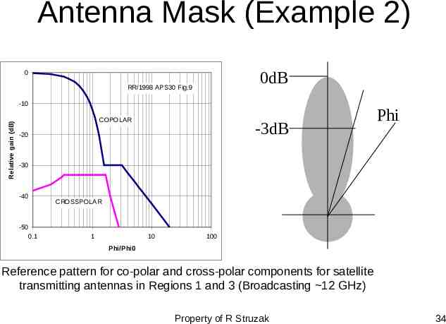
Antenna Mask (Example 2) 0dB 0 RR/1998 APS30 Fig.9 Relative gain (dB) -10 COPOLAR -3dB -20 Phi -30 -40 CROSSPOLAR -50 0.1 1 10 100 Phi/Phi0 Reference pattern for co-polar and cross-polar components for satellite transmitting antennas in Regions 1 and 3 (Broadcasting 12 GHz) Property of R Struzak 34
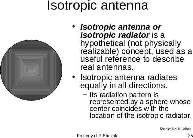
Isotropic antenna Isotropic antenna or isotropic radiator is a hypothetical (not physically realizable) concept, used as a useful reference to describe real antennas. Isotropic antenna radiates equally in all directions. – Its radiation pattern is represented by a sphere whose center coincides with the location of the isotropic radiator. Source: NK Nikolova Property of R Struzak 35
Directional antenna Directional antenna is an antenna, which radiates (or receives) much more power in (or from) some directions than in (or from) others. – Note: Usually, this term is applied to antennas whose directivity is much higher than that of a half-wavelength dipole. Source: NK Nikolova Property of R Struzak 36
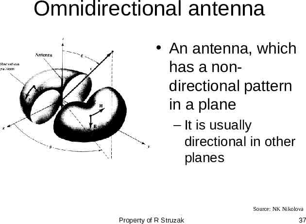
Omnidirectional antenna An antenna, which has a nondirectional pattern in a plane – It is usually directional in other planes Source: NK Nikolova Property of R Struzak 37
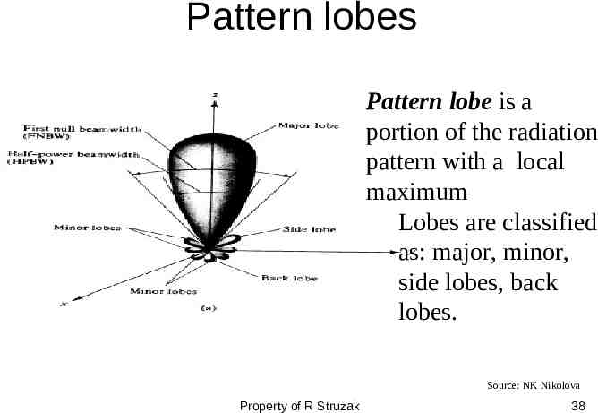
Pattern lobes Pattern lobe is a portion of the radiation pattern with a local maximum Lobes are classified as: major, minor, side lobes, back lobes. Source: NK Nikolova Property of R Struzak 38
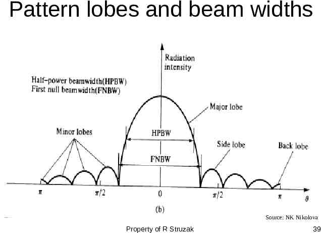
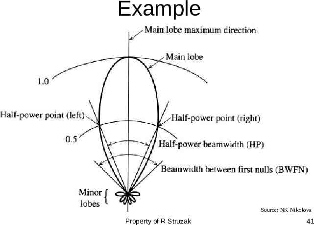
Pattern lobes and beam widths Source: NK Nikolova Property of R Struzak 39
Beamwidth Half-power beamwidth (HPBW) is the angle between two vectors from the pattern’s origin to the points of the major lobe where the radiation intensity is half its maximum Often used to describe the antenna resolution properties » Important in radar technology, radioastronomy, etc. First-null beamwidth (FNBW) is the angle between two vectors, originating at the pattern’s origin and tangent to the main beam at its base. » Often FNBW 2*HPBW Property of R Struzak 40
Example Source: NK Nikolova Property of R Struzak 41
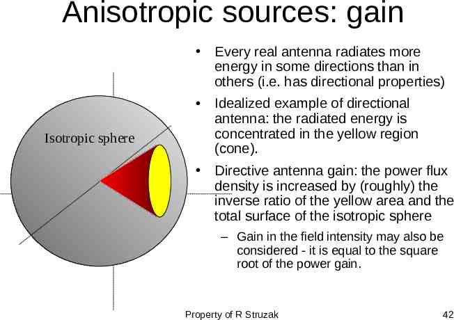
Anisotropic sources: gain Every real antenna radiates more energy in some directions than in others (i.e. has directional properties) Isotropic sphere Idealized example of directional antenna: the radiated energy is concentrated in the yellow region (cone). Directive antenna gain: the power flux density is increased by (roughly) the inverse ratio of the yellow area and the total surface of the isotropic sphere – Gain in the field intensity may also be considered - it is equal to the square root of the power gain. Property of R Struzak 42
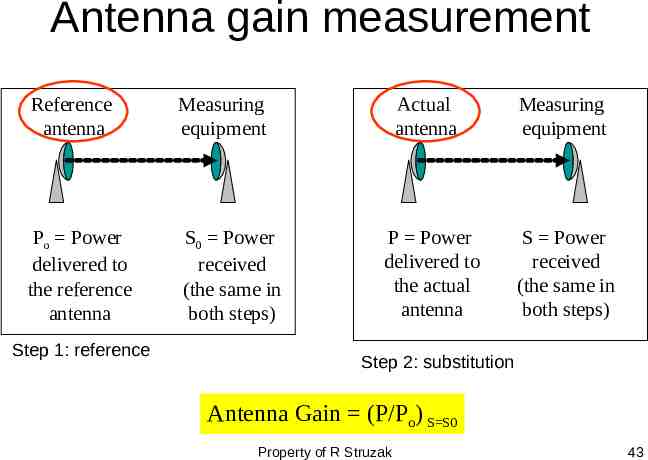
Antenna gain measurement Reference antenna Measuring equipment Po Power delivered to the reference antenna S0 Power received (the same in both steps) Step 1: reference Actual antenna Measuring equipment P Power delivered to the actual antenna S Power received (the same in both steps) Step 2: substitution Antenna Gain (P/Po) S S0 Property of R Struzak 43
Antenna Gains Gi, Gd Unless otherwise specified, the gain refers to the direction of maximum radiation. Gain is a dimension-less factor related to power and usually expressed in decibels Gi “Isotropic Power Gain” – theoretical concept, the reference antenna is isotropic Gd - the reference antenna is a half-wave dipole Property of R Struzak 44
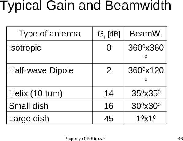
Typical Gain and Beamwidth Type of antenna Gi [dB] BeamW. 0 3600x360 Isotropic 0 Half-wave Dipole 2 3600x120 0 Helix (10 turn) Small dish Large dish 14 16 45 Property of R Struzak 350x350 300x300 10x10 46
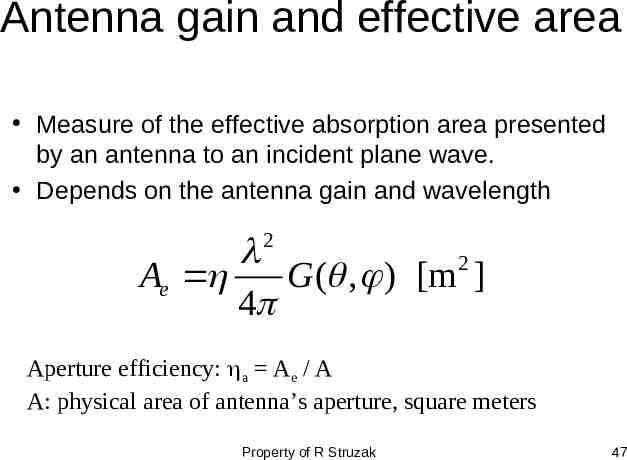
Antenna gain and effective area Measure of the effective absorption area presented by an antenna to an incident plane wave. Depends on the antenna gain and wavelength 2 2 Ae G ( , ) [m ] 4 Aperture efficiency: a Ae / A A: physical area of antenna’s aperture, square meters Property of R Struzak 47
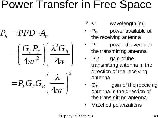
Power Transfer in Free Space PR PFD Ae GT PT 2 4 r 2 GR 4 PT GT GR 4 r 2 : wavelength [m] PR: power available at the receiving antenna PT: power delivered to the transmitting antenna G R: gain of the transmitting antenna in the direction of the receiving antenna G T: gain of the receiving antenna in the direction of the transmitting antenna Matched polarizations Property of R Struzak 48
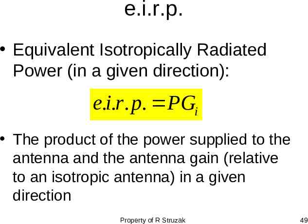
e.i.r.p. Equivalent Isotropically Radiated Power (in a given direction): e.i.r. p. PGi The product of the power supplied to the antenna and the antenna gain (relative to an isotropic antenna) in a given direction Property of R Struzak 49
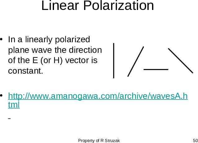
Linear Polarization In a linearly polarized plane wave the direction of the E (or H) vector is constant. http://www.amanogawa.com/archive/wavesA.h tml Property of R Struzak 50
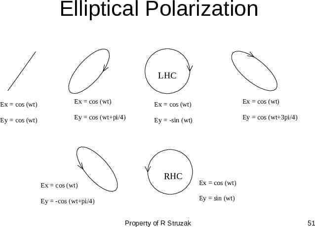
Elliptical Polarization LHC Ex cos (wt) Ex cos (wt) Ex cos (wt) Ex cos (wt) Ey cos (wt) Ey cos (wt pi/4) Ey -sin (wt) Ey cos (wt 3pi/4) RHC Ex cos (wt) Ex cos (wt) Ey -cos (wt pi/4) Ey sin (wt) Property of R Struzak 51
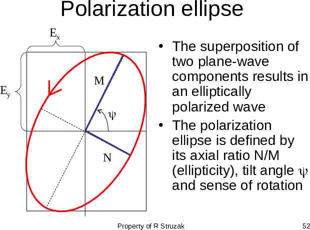
Polarization ellipse Ex Ey M N The superposition of two plane-wave components results in an elliptically polarized wave The polarization ellipse is defined by its axial ratio N/M (ellipticity), tilt angle and sense of rotation Property of R Struzak 52
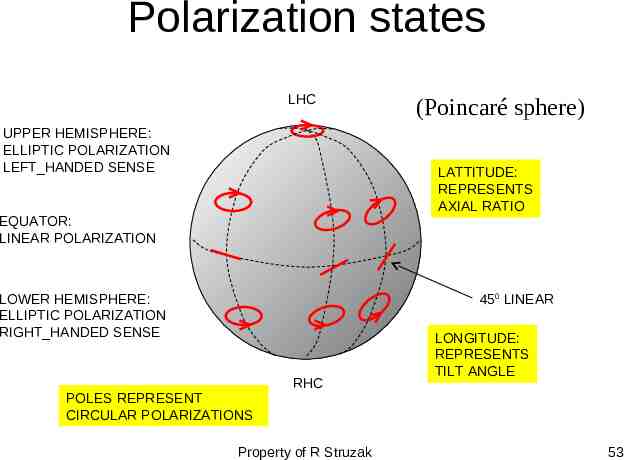
Polarization states LHC UPPER HEMISPHERE: ELLIPTIC POLARIZATION LEFT HANDED SENSE (Poincaré sphere) LATTITUDE: REPRESENTS AXIAL RATIO EQUATOR: LINEAR POLARIZATION LOWER HEMISPHERE: ELLIPTIC POLARIZATION RIGHT HANDED SENSE 450 LINEAR POLES REPRESENT CIRCULAR POLARIZATIONS RHC Property of R Struzak LONGITUDE: REPRESENTS TILT ANGLE 53
Comments on Polarization At any moment in a chosen reference point in space, there is actually a single electric vector E (and associated magnetic vector H). This is the result of superposition (addition) of the instantaneous fields E (and H) produced by all radiation sources active at the moment. The separation of fields by their wavelength, polarization, or direction is the result of ‘filtration’. Property of R Struzak 54
Antenna Polarization The polarization of an antenna in a specific direction is defined to be the polarization of the wave produced by the antenna at a great distance at this direction Property of R Struzak 55
Polarization Efficiency The power received by an antenna from a particular direction is maximal if the polarization of the incident wave and the polarization of the antenna in the wave arrival direction have: – the same axial ratio – the same sense of polarization – the same spatial orientation . Property of R Struzak 56
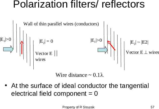
Polarization filters/ reflectors Wall of thin parallel wires (conductors) E1 0 E1 0 E2 0 E2 E2 Vector E wires Vector E wires Wire distance 0.1 At the surface of ideal conductor the tangential electrical field component 0 Property of R Struzak 57
Outline Introduction Review of basic antenna types Radiation pattern, gain, polarization Equivalent circuit & radiation efficiency Smart antennas Some theory Summary Property of R Struzak 58
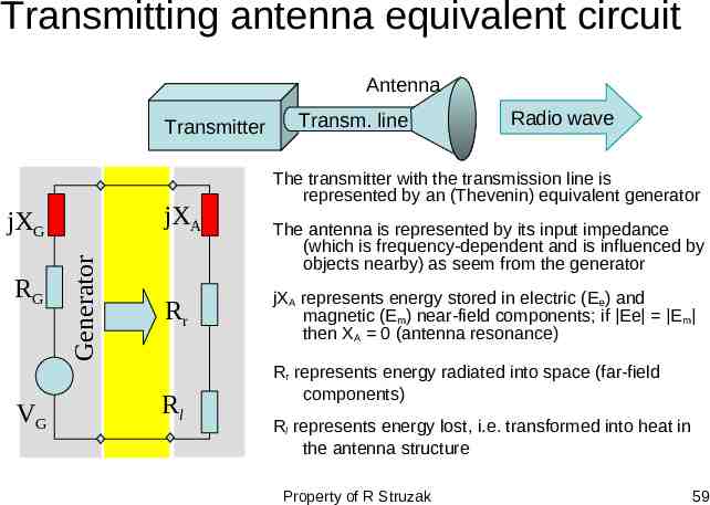
Transmitting antenna equivalent circuit Antenna Transmitter jXA RG VG Generator jXG Rr Rl Transm. line Radio wave The transmitter with the transmission line is represented by an (Thevenin) equivalent generator The antenna is represented by its input impedance (which is frequency-dependent and is influenced by objects nearby) as seem from the generator jXA represents energy stored in electric (E e) and magnetic (Em) near-field components; if Ee E m then XA 0 (antenna resonance) Rr represents energy radiated into space (far-field components) Rl represents energy lost, i.e. transformed into heat in the antenna structure Property of R Struzak 59
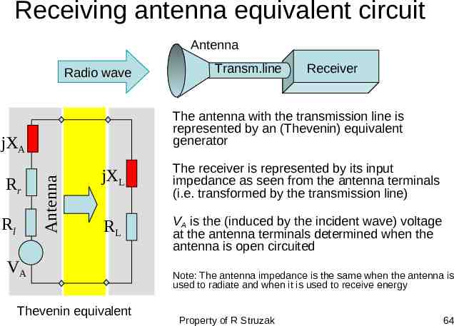
Receiving antenna equivalent circuit Antenna Radio wave Antenna Rl Receiver The antenna with the transmission line is represented by an (Thevenin) equivalent generator jXA Rr Transm.line jXL The receiver is represented by its input impedance as seen from the antenna terminals (i.e. transformed by the transmission line) RL VA is the (induced by the incident wave) voltage at the antenna terminals determined when the antenna is open circuited VA Thevenin equivalent Note: The antenna impedance is the same when the antenna is used to radiate and when it is used to receive energy Property of R Struzak 64
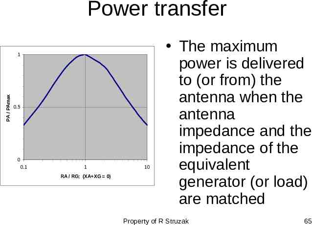
Power transfer PA / PAmax 1 0.5 0 0.1 1 RA / RG; (XA XG 0) 10 The maximum power is delivered to (or from) the antenna when the antenna impedance and the impedance of the equivalent generator (or load) are matched Property of R Struzak 65
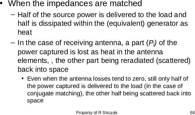
When the impedances are matched – Half of the source power is delivered to the load and half is dissipated within the (equivalent) generator as heat – In the case of receiving antenna, a part (Pl) of the power captured is lost as heat in the antenna elements, , the other part being reradiated (scattered) back into space Even when the antenna losses tend to zero, still only half of the power captured is delivered to the load (in the case of conjugate matching), the other half being scattered back into space Property of R Struzak 66
When the antenna impedance is not matched to the transmitter output impedance (or to the receiver input impedance) or to the transmission line between them, impedance-matching devices must be used for maximum power transfer Inexpensive impedance-matching devices are usually narrow-band Transmission lines often have significant losses Property of R Struzak 67
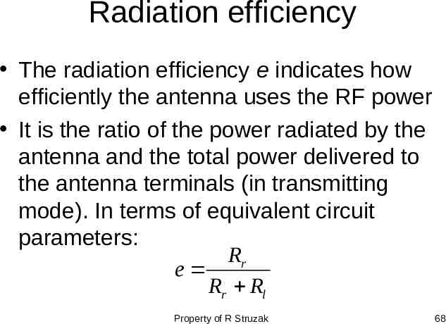
Radiation efficiency The radiation efficiency e indicates how efficiently the antenna uses the RF power It is the ratio of the power radiated by the antenna and the total power delivered to the antenna terminals (in transmitting mode). In terms of equivalent circuit parameters: Rr e Rr Rl Property of R Struzak 68
Outline Introduction Review of basic antenna types Radiation pattern, gain, polarization Equivalent circuit & radiation efficiency Smart antennas Some theory Summary Property of R Struzak 69
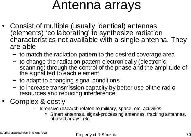
Antenna arrays Consist of multiple (usually identical) antennas (elements) ‘collaborating’ to synthesize radiation characteristics not available with a single antenna. They are able – to match the radiation pattern to the desired coverage area – to change the radiation pattern electronically (electronic scanning) through the control of the phase and the amplitude of the signal fed to each element – to adapt to changing signal conditions – to increase transmission capacity by better use of the radio resources and reducing interference Complex & costly – Intensive research related to military, space, etc. activities » Smart antennas, signal-processing antennas, tracking antennas, phased arrays, etc. Source: adapted from N Gregorieva Property of R Struzak 70
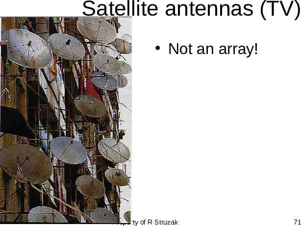
Satellite antennas (TV) Not an array! Property of R Struzak 71
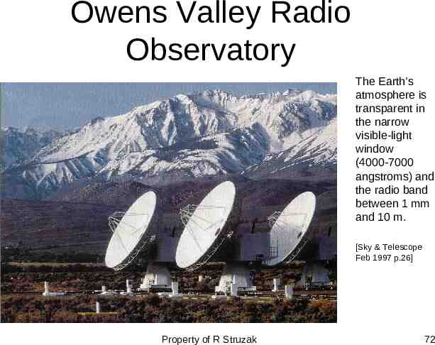
Owens Valley Radio Observatory The Earth’s atmosphere is transparent in the narrow visible-light window (4000-7000 angstroms) and the radio band between 1 mm and 10 m. [Sky & Telescope Feb 1997 p.26] Property of R Struzak 72
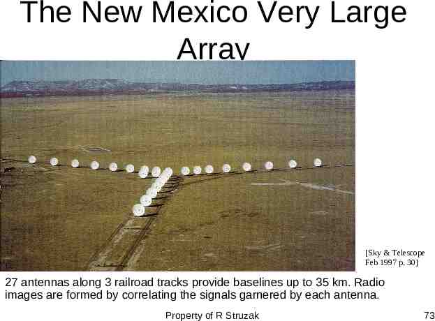
The New Mexico Very Large Array [Sky & Telescope Feb 1997 p. 30] 27 antennas along 3 railroad tracks provide baselines up to 35 km. Radio images are formed by correlating the signals garnered by each antenna. Property of R Struzak 73
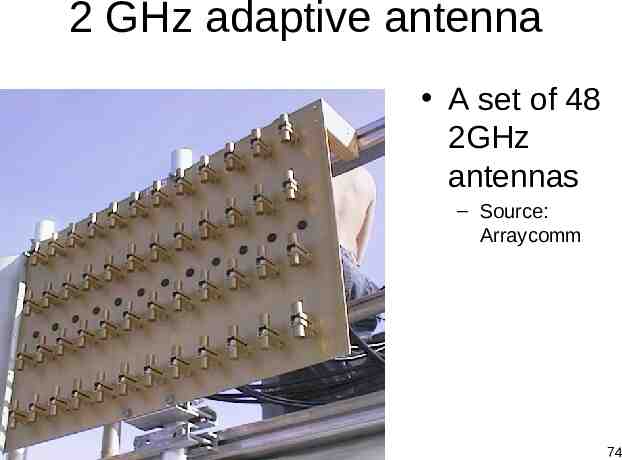
2 GHz adaptive antenna A set of 48 2GHz antennas – Source: Arraycomm Property of R Struzak 74
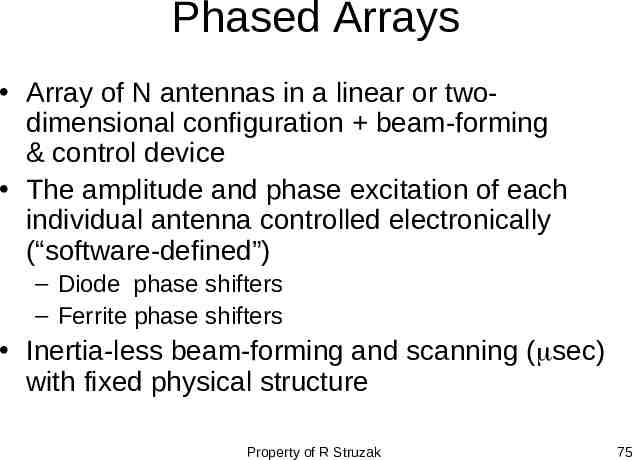
Phased Arrays Array of N antennas in a linear or twodimensional configuration beam-forming & control device The amplitude and phase excitation of each individual antenna controlled electronically (“software-defined”) – Diode phase shifters – Ferrite phase shifters Inertia-less beam-forming and scanning ( sec) with fixed physical structure Property of R Struzak 75
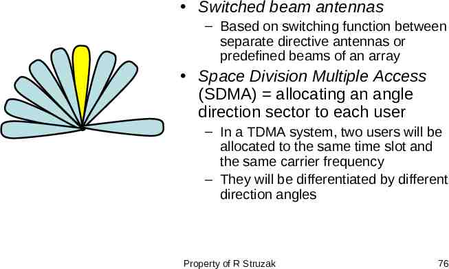
Switched beam antennas – Based on switching function between separate directive antennas or predefined beams of an array Space Division Multiple Access (SDMA) allocating an angle direction sector to each user – In a TDMA system, two users will be allocated to the same time slot and the same carrier frequency – They will be differentiated by different direction angles Property of R Struzak 76
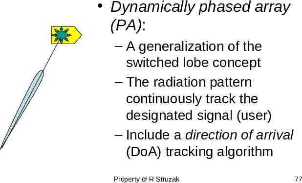
Dynamically phased array (PA): – A generalization of the switched lobe concept – The radiation pattern continuously track the designated signal (user) – Include a direction of arrival (DoA) tracking algorithm Property of R Struzak 77
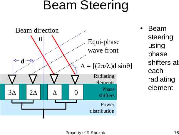
Beam Steering Beam direction Equi-phase wave front d 3 [(2 / )d sin ] 2 0 Radiating elements Phase shifters Beamsteering using phase shifters at each radiating element Power distribution Property of R Struzak 78
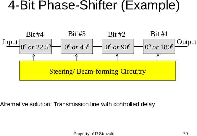
4-Bit Phase-Shifter (Example) Input Bit #3 Bit #4 0 or 22.5 0 0 0 or 45 0 Bit #1 Bit #2 0 0 or 90 0 0 0 or 180 0 0 Output Steering/ Beam-forming Circuitry Alternative solution: Transmission line with controlled delay Property of R Struzak 79
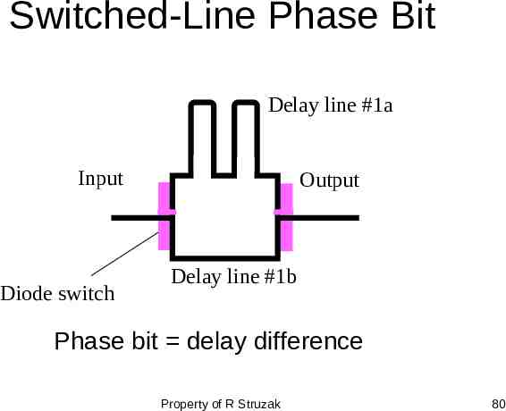
Switched-Line Phase Bit Delay line #1a Input Diode switch Output Delay line #1b Phase bit delay difference Property of R Struzak 80
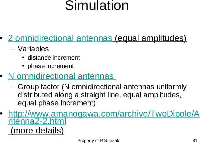
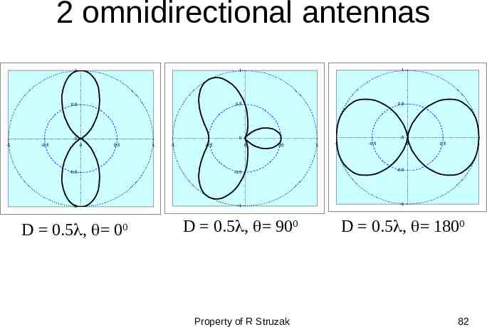
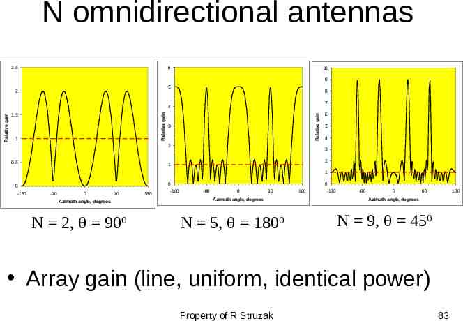
Simulation 2 omnidirectional antennas (equal amplitudes) – Variables distance increment phase increment N omnidirectional antennas – Group factor (N omnidirectional antennas uniformly distributed along a straight line, equal amplitudes, equal phase increment) http://www.amanogawa.com/archive/TwoDipole/A ntenna2-2.html (more details) Property of R Struzak 81
2 omnidirectional antennas 1 1 1 0.5 0.5 0.5 -0.5 0 0 0 -1 0 0.5 1 -1 -0.5 0 0.5 1 -1 -0.5 0 0.5 1 -0.5 -0.5 -0.5 -1 -1 -1 D 0.5 , 900 D 0.5 , 1800 D 0.5 , 00 Property of R Struzak 82
N omnidirectional antennas 6 2.5 10 9 5 2 8 7 1 Relative gain 1.5 Relative gain Relative gain 4 3 2 0.5 6 5 4 3 2 1 1 0 -180 0 0 -90 0 90 Azimuth angle, degrees N 2, 900 180 -180 -90 0 90 Azimuth angle, degrees N 5, 1800 180 -180 -90 0 90 180 Azimuth angle, degrees N 9, 450 Array gain (line, uniform, identical power) Property of R Struzak 83
Antenna Arrays: Benefits Possibilities to control electronically – – – – – Direction of maximum radiation Directions (positions) of nulls Beam-width Directivity Levels of sidelobes using standard antennas (or antenna collections) independently of their radiation patterns Antenna elements can be distributed along straight lines, arcs, squares, circles, etc. Property of R Struzak 84
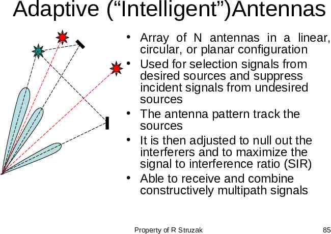
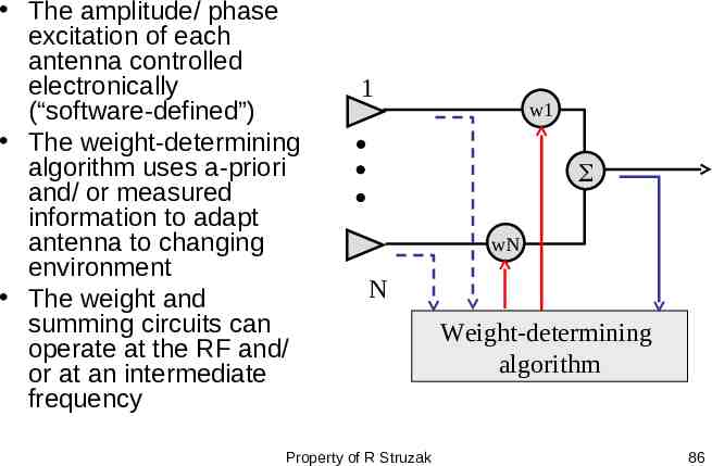
Adaptive (“Intelligent”)Antennas Array of N antennas in a linear, circular, or planar configuration Used for selection signals from desired sources and suppress incident signals from undesired sources The antenna pattern track the sources It is then adjusted to null out the interferers and to maximize the signal to interference ratio (SIR) Able to receive and combine constructively multipath signals Property of R Struzak 85
The amplitude/ phase excitation of each antenna controlled electronically (“software-defined”) The weight-determining algorithm uses a-priori and/ or measured information to adapt antenna to changing environment The weight and summing circuits can operate at the RF and/ or at an intermediate frequency 1 w1 wN N Property of R Struzak Weight-determining algorithm 86
Antenna sitting Radio horizon Effects of obstacles & structures nearby Safety – operating procedures – Grounding lightning strikes static charges – Surge protection lightning searches for a second path to ground Property of R Struzak 87
Outline Introduction Review of basic antenna types Radiation pattern, gain, polarization Equivalent circuit & radiation efficiency Smart antennas Some theory Summary Property of R Struzak 88
Maxwell’s Equations EM field interacting with the matter – 2 coupled vectors E and H (6 numbers!), varying with time and space and satisfying the boundary conditions (see http://www.amanogawa.com/archive/docs/EM1.pdf; http://www.amanogawa.com/archive/docs/EM7.pdf; http://www.amanogawa.com/archive/docs/EM5.pdf) Reciprocity Theorem – Antenna characteristics do not depend on the direction of energy flow. The impedance & radiation pattern are the same when the antenna radiates signal and when it receives it. – Note: This theorem is valid only for linear passive antennas (i.e. antennas that do not contain nonlinear and unilateral elements, e.g. amplifiers) Property of R Struzak 89
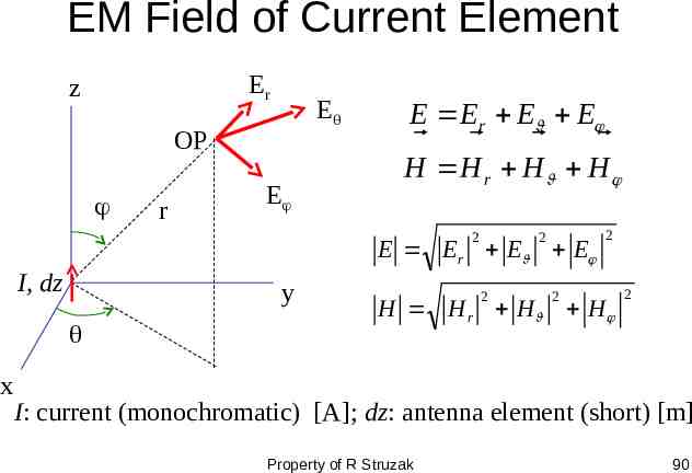
EM Field of Current Element Er z E OP r E E Er E E H H r H H 2 2 E Er E E I, dz y x 2 2 2 H H r H H 2 I: current (monochromatic) [A]; dz: antenna element (short) [m] Property of R Struzak 90
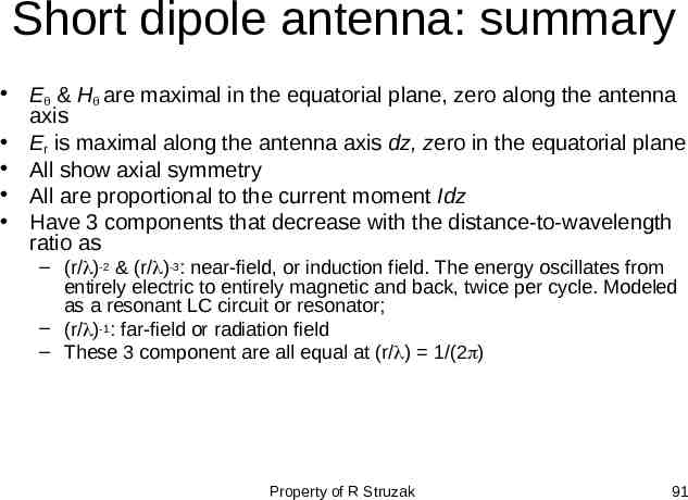
Short dipole antenna: summary E & H are maximal in the equatorial plane, zero along the antenna axis Er is maximal along the antenna axis dz, zero in the equatorial plane All show axial symmetry All are proportional to the current moment Idz Have 3 components that decrease with the distance-to-wavelength ratio as – (r/ )-2 & (r/ )-3: near-field, or induction field. The energy oscillates from entirely electric to entirely magnetic and back, twice per cycle. Modeled as a resonant LC circuit or resonator; – (r/ )-1: far-field or radiation field – These 3 component are all equal at (r/ ) 1/(2 ) Property of R Struzak 91
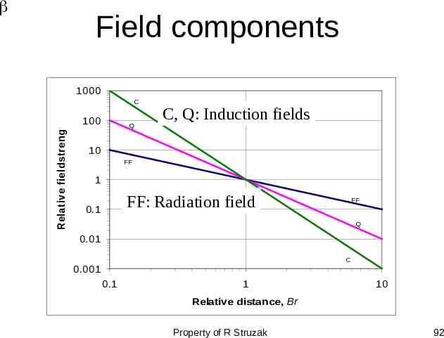
Field components 1000 Relative fieldstrength C 100 Q C, Q: Induction fields 10 FF 1 FF: Radiation field 0.1 FF Q 0.01 C 0.001 0.1 1 10 Relative distance, Br Property of R Struzak 92
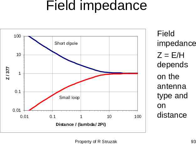
Field impedance 100 Short dipole Z / 377 10 1 0.1 Small loop 0.01 0.01 0.1 1 10 100 Field impedance Z E/H depends on the antenna type and on distance Distance / (lambda/ 2Pi) Property of R Struzak 93
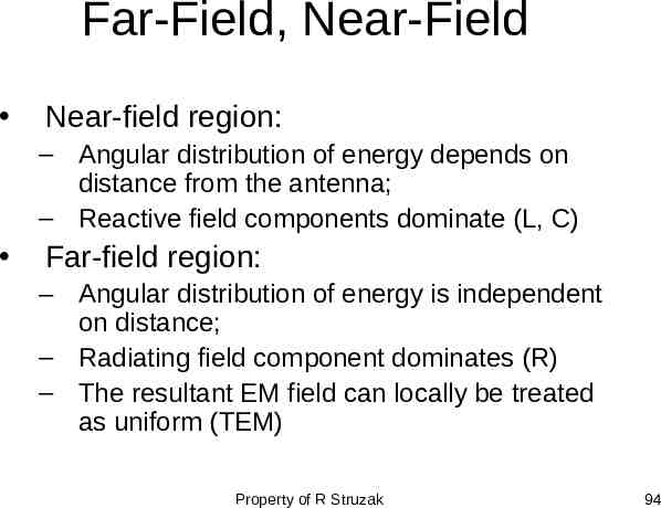
Far-Field, Near-Field Near-field region: – Angular distribution of energy depends on distance from the antenna; – Reactive field components dominate (L, C) Far-field region: – Angular distribution of energy is independent on distance; – Radiating field component dominates (R) – The resultant EM field can locally be treated as uniform (TEM) Property of R Struzak 94
Poynting vector The time-rate of EM energy flow per unit area in free space is the Poynting vector (see http://www.amanogawa.com/archive/docs/EM8.pdf). It is the cross-product (vector product, right-hand screw direction) of the electric field vector (E) and the magnetic field vector (H): P E x H. For the elementary dipole E H and only E xH carry energy into space with the speed of light. Property of R Struzak 95
Power Flow In free space and at large distances, the radiated energy streams from the antenna in radial lines, i.e. the Poynting vector has only the radial component in spherical coordinates. A source that radiates uniformly in all directions is an isotropic source (radiator, antenna). For such a source the radial component of the Poynting vector is independent of and . Property of R Struzak 96
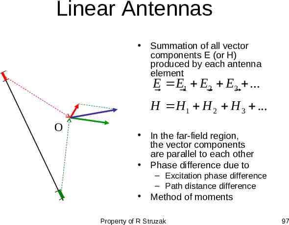
Linear Antennas Summation of all vector components E (or H) produced by each antenna element E E1 E2 E3 . H H1 H 2 H 3 . O In the far-field region, the vector components are parallel to each other Phase difference due to – Excitation phase difference – Path distance difference Method of moments Property of R Struzak 97
Simulation: Linear dipole antenna http://www.amanogawa.com/archive/Dipol eAnt/DipoleAnt-2.html – Linear dipole antenna http://www.amanogawa.com/archive/Anten na1/Antenna1-2.html – Detailed analysis Property of R Struzak 98
Point Source For many purposes, it is sufficient to know the direction (angle) variation of the power radiated by antenna at large distances. For that purpose, any practical antenna, regardless of its size and complexity, can be represented as a point-source. The actual field near the antenna is then disregarded. Property of R Struzak 99
The EM field at large distances from an antenna can be treated as originated at a point source - fictitious volume-less emitter. The EM field in a homogenous unlimited medium at large distances from an antenna can be approximated by an uniform plane TEM wave Property of R Struzak 100
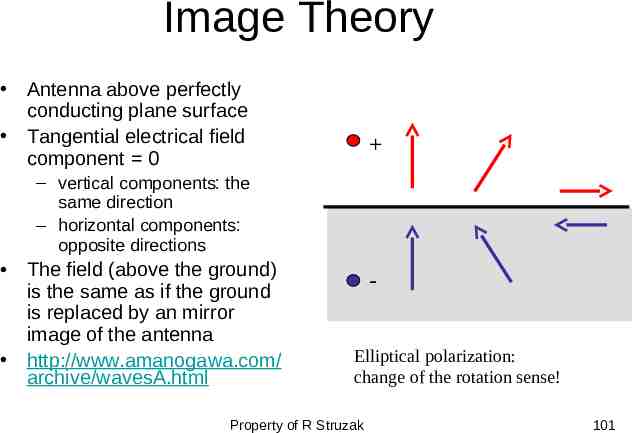
Image Theory Antenna above perfectly conducting plane surface Tangential electrical field component 0 – vertical components: the same direction – horizontal components: opposite directions The field (above the ground) is the same as if the ground is replaced by an mirror image of the antenna http://www.amanogawa.com/ archive/wavesA.html Elliptical polarization: change of the rotation sense! Property of R Struzak 101
Summary Introduction Review of basic antenna types Radiation pattern, gain, polarization Equivalent circuit & radiation efficiency Smart antennas Some theory Property of R Struzak 102
Selected References Nikolova N K: Modern Antennas in Wireless Telecommunications EE753 (lecture notes) [email protected] Griffiths H & Smith BL (ed.): Modern antennas; Chapman & Hall, 1998 Johnson RC: Antenna Engineering Handbook McGraw-Hill Book Co. 1993 Kraus JD: Antennas, McGraw-Hill Book Co. 1998 Scoughton TE: Antenna Basics Tutorial; Microwave Journal Jan. 1998, p. 186-191 Stutzman WL, Thiele GA: Antenna Theory and Design JWiley &Sons, 1981 http://amanogawa.com Software – – – – http://www.feko.co.za/apl ant pla.htm Li et al., “Microcomputer Tools for Communication Engineering” Pozar D. “Antenna Design Using Personal Computers” NEC Archives www.gsl.net/wb6tpu /swindex.html () Property of R Struzak 103
Any questions? Thank you for your attention Property of R Struzak 104