An Overview of the Technical Work of the MEF MEF Reference


65 Slides2.51 MB
An Overview of the Technical Work of the MEF MEF Reference Presentation October 2011 1
MEF Reference Presentations Intention – These MEF reference presentations are intended to give general overviews of the MEF work and have been approved by the MEF Marketing Committee – Further details on the topic are to be found in related specifications, technical overviews, white papers in the MEF public site Information Center: http://metroethernetforum.org/InformationCenter Notice The Metro Ethernet Forum 2011. Any reproduction of this document, or any portion thereof, shall contain the following statement: "Reproduced with permission of the Metro Ethernet Forum." No user of this document is authorized to modify any of the information contained herein. 2
Session Topics Overview of the Technical Work The Specifications – Summaries & recent specifications Relationship to other standards bodies Technical work in development 3
MEF Technical Committee Technical Committee – The Technical Committee is organized into Services, Architecture, Management, Test & Measurement. – The Technical Committee has active liaisons with other standards organizations. Technical Overview of the Work of the MEF Standards – The technical committee develops technical specifications, implementation agreements, test specifications and position statements – A list of the Specifications, timelines, etc., follows – Detailed technical presentations are available on the MEF web site www.metroethernetforum.org/presentations www.metroethernetforum.org/techspecs 4
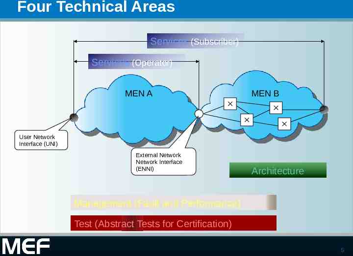
Four Technical Areas Services (Subscriber) Services (Operator) MEN A MEN B User Network Interface (UNI) External Network Network Interface (ENNI) Architecture Management (Fault and Performance) Test (Abstract Tests for Certification) 5
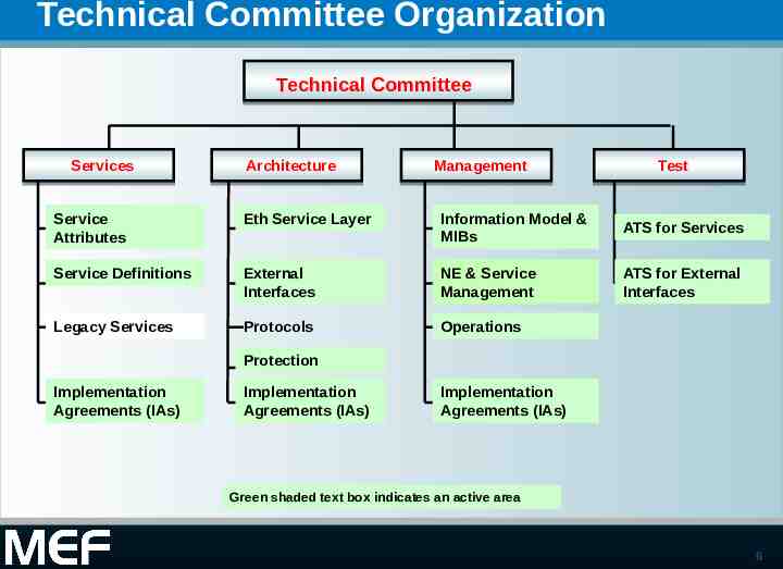
Technical Committee Organization Technical Committee Services Architecture Management Test Service Attributes Eth Service Layer Information Model & MIBs ATS for Services Service Definitions External Interfaces NE & Service Management ATS for External Interfaces Legacy Services Protocols Operations Protection Implementation Agreements (IAs) Implementation Agreements (IAs) Implementation Agreements (IAs) Green shaded text box indicates an active area 6
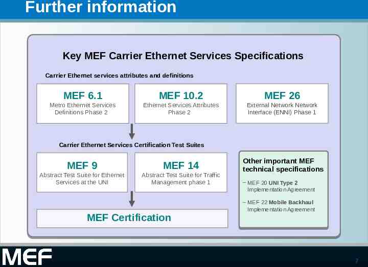
Further information Key MEF Carrier Ethernet Services Specifications Carrier Ethernet services attributes and definitions MEF 6.1 MEF 10.2 MEF 26 Metro Ethernet Services Definitions Phase 2 Ethernet Services Attributes Phase 2 External Network Network Interface (ENNI) Phase 1 Carrier Ethernet Services Certification Test Suites MEF 9 MEF 14 Abstract Test Suite for Ethernet Services at the UNI Abstract Test Suite for Traffic Management phase 1 MEF Certification Other important MEF technical specifications – MEF 20 UNI Type 2 Implementation Agreement – MEF 22 Mobile Backhaul Implementation Agreement 7
MEF Specifications 8
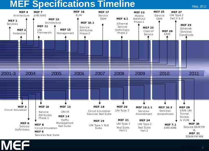
MEF Specifications Timeline MEF 4 Architecture MEF 12 Architecture MEF 11 MEF 15 UNI Framework Management MEF 1 Services MEF 2 Protection 2001-3 2005 2004 MEF 3 Circuit Emulation MEF 6 Service Definitions MEF 16 ELMI MEF 7 EMS-NMS MEF 10 Service Attributes Phase 1 MEF 17 Service OAM MEF 10.1 Ethernet Service Definitions Phase 2 Service Attributes Phase 2 2006 2007 MEF 13 MEF 18 UNI-IA Circuit Emulation Services Test Suite MEF 14 Traffic Management MEF 8 Test Suite Circuit Emulation MEF 9 Services Test Suite MEF 6.1 MEF 19 UNI Type 1 Test Suite 2008 MEF 20 UNI Type 2 MEF 21 UNI Type 2 Test Suite Part 1 May, 2011 MEF 22 Mobile Backhaul Phase 1 MEF 23 Class of Service 2009 MEF 10.1.1 Services Amendment MEF 24 UNI Type 2 Test Suite Part 2 MEF 25 Service OAM MEF 27 UNI Type 2 Part 5 & 6 MEF 26 ENNI 2010 MEF 29 Ethernet Services Constructs 2011 MEF 28 ENNI UNI Tunnel Access & VUNI MEF 30 MEF 7.1 Service OAM FM EMS-NMS IA MEF 31 SOAM FM MIB MEF 10.2 Services Amendment (KR May 3 2011) 9
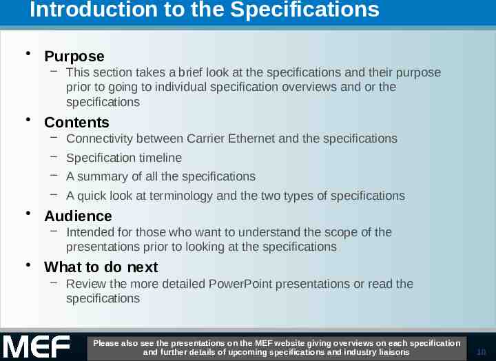
Introduction to the Specifications Purpose – This section takes a brief look at the specifications and their purpose prior to going to individual specification overviews and or the specifications Contents – Connectivity between Carrier Ethernet and the specifications – Specification timeline – A summary of all the specifications – A quick look at terminology and the two types of specifications Audience – Intended for those who want to understand the scope of the presentations prior to looking at the specifications What to do next – Review the more detailed PowerPoint presentations or read the specifications Please also see the presentations on the MEF website giving overviews on each specification and further details of upcoming specifications and industry liaisons 10
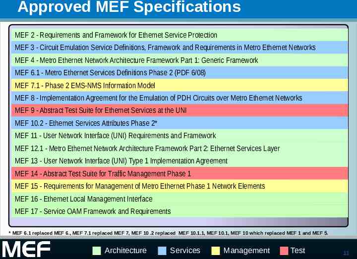
Approved MEF Specifications MEF 2 - Requirements and Framework for Ethernet Service Protection MEF 3 - Circuit Emulation Service Definitions, Framework and Requirements in Metro Ethernet Networks MEF 4 - Metro Ethernet Network Architecture Framework Part 1: Generic Framework MEF 6.1 - Metro Ethernet Services Definitions Phase 2 (PDF 6/08) MEF 7.1 - Phase 2 EMS-NMS Information Model MEF 8 - Implementation Agreement for the Emulation of PDH Circuits over Metro Ethernet Networks MEF 9 - Abstract Test Suite for Ethernet Services at the UNI MEF 10.2 - Ethernet Services Attributes Phase 2* MEF 11 - User Network Interface (UNI) Requirements and Framework MEF 12.1 - Metro Ethernet Network Architecture Framework Part 2: Ethernet Services Layer MEF 13 - User Network Interface (UNI) Type 1 Implementation Agreement MEF 14 - Abstract Test Suite for Traffic Management Phase 1 MEF 15 - Requirements for Management of Metro Ethernet Phase 1 Network Elements MEF 16 - Ethernet Local Management Interface MEF 17 - Service OAM Framework and Requirements * MEF 6.1 replaced MEF 6., MEF 7.1 replaced MEF 7, MEF 10 .2 replaced MEF 10.1.1, MEF 10.1, MEF 10 which replaced MEF 1 and MEF 5. Architecture Services Management Test 11
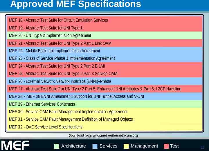
Approved MEF Specifications MEF 18 - Abstract Test Suite for Circuit Emulation Services MEF 19 - Abstract Test Suite for UNI Type 1 MEF 20 - UNI Type 2 Implementation Agreement MEF 21 - Abstract Test Suite for UNI Type 2 Part 1 Link OAM MEF 22 - Mobile Backhaul Implementation Agreement MEF 23 - Class of Service Phase 1 Implementation Agreement MEF 24 - Abstract Test Suite for UNI Type 2 Part 2 E-LMI MEF 25 - Abstract Test Suite for UNI Type 2 Part 3 Service OAM MEF 26 - External Network Network Interface (ENNI)–Phase MEF 27 - Abstract Test Suite For UNI Type 2 Part 5: Enhanced UNI Attributes & Part 6: L2CP Handling MEF 28 - MEF 28 ENNI Amendment: Support for UNI Tunnel Access and V-UNI MEF 29 - Ethernet Services Constructs MEF 30 - Service OAM Fault Management Implementation Agreement MEF 31 - Service OAM Fault Management Definition of Managed Objects MEF 32 - OVC Service Level Specifications Download from www.metroethernetforum.org Architecture Services Management Test 12
MEF Technical Dashboard Please see the current Technical Dashboard of work in progress on the MEF public web site http://metroethernetforum.org/page loader.php?p id 79 13
Relationship to other Standards Bodies 14
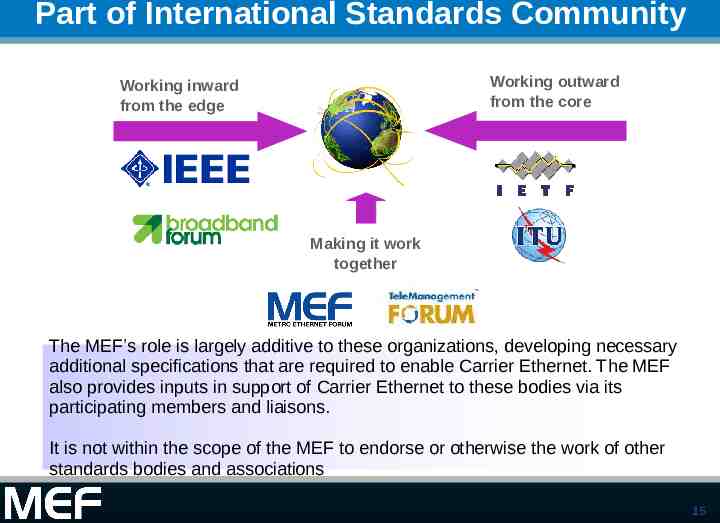
Part of International Standards Community Working outward from the core Working inward from the edge Making it work together The MEF’s role is largely additive to these organizations, developing necessary additional specifications that are required to enable Carrier Ethernet. The MEF also provides inputs in support of Carrier Ethernet to these bodies via its participating members and liaisons. It is not within the scope of the MEF to endorse or otherwise the work of other standards bodies and associations 15
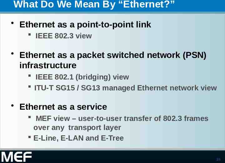
What Do We Mean By “Ethernet?” Ethernet as a point-to-point link IEEE 802.3 view Ethernet as a packet switched network (PSN) infrastructure IEEE 802.1 (bridging) view ITU-T SG15 / SG13 managed Ethernet network view Ethernet as a service MEF view – user-to-user transfer of 802.3 frames over any transport layer E-Line, E-LAN and E-Tree 16
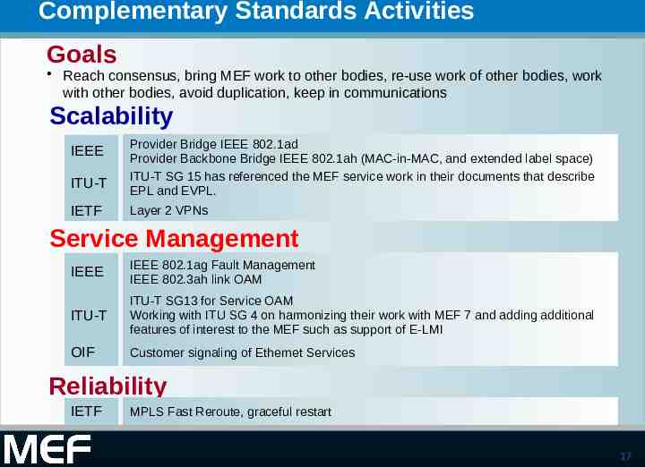
Complementary Standards Activities Goals Reach consensus, bring MEF work to other bodies, re-use work of other bodies, work with other bodies, avoid duplication, keep in communications Scalability ITU-T Provider Bridge IEEE 802.1ad Provider Backbone Bridge IEEE 802.1ah (MAC-in-MAC, and extended label space) ITU-T SG 15 has referenced the MEF service work in their documents that describe EPL and EVPL. IETF Layer 2 VPNs IEEE Service Management IEEE IEEE 802.1ag Fault Management IEEE 802.3ah link OAM ITU-T ITU-T SG13 for Service OAM Working with ITU SG 4 on harmonizing their work with MEF 7 and adding additional features of interest to the MEF such as support of E-LMI OIF Customer signaling of Ethernet Services Reliability IETF MPLS Fast Reroute, graceful restart 17
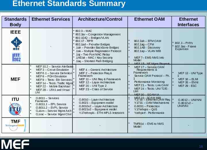
Ethernet Standards Summary Standards Body Ethernet Services IEEE - MEF Architecture/Control MEF 10.2 – Service Attributes MEF 3 – Circuit Emulation MEF 6.1 – Service Definition MEF 8 – PDH Emulation MEF 9 – Tests: Eth Services MEF 14 – Tests: Traffic Mgmt. MEF 22 - Mobile Backhaul MEF 28 – UTAS and Virtual 802.3 – MAC 802.3ar – Congestion Management 802.1D/Q – Bridges/VLAN 802.17 - RPR 802.1ad – Provider Bridges .1ah – Provider Backbone Bridges .1ak – Multiple Registration Protocol .1aj – Two Port MAC Relay .1AE/af – MAC / Key Security .1aq – Shortest Path Bridging MEF 4 – Generic Architecture MEF 2 – Protection Req & Framework MEF 11 – UNI Req & Framework MEF 12 – Layer Architecture MEF 20 – UNI Type 2 MEF 23 – Class of Service UNI ITU TMF G.8011 – Services Framewrk G.8011.1 – EPL Service G.8011.2 – EVPL Service G.asm – Service Mgmt Arch G.smc – Service Mgmt Chnl - G.8010 – Layer Architecture G.8021 – Equipment model G.8010v2 – Layer Architecture G.8021v2 – Equipment model Y.17ethmpls - ETH-MPLS Interwork - Ethernet OAM 802.3ah – EFM OAM 802.1ag – CFM 802.1AB - Discovery 802.1ap – VLAN MIB MEF 7– EMS-NMS Info Model MEF 15– NE Mgmt Reqrmts. MEF 17 – Service OAM Requirements & Framework Service OAM Protocol – Ph. 1 Performance Monitoring MEF 21 – Tests: Link OAM MEF 24 – Tests: UNI T2/ELMI MEF 30 – SOAM IA MEF 31– SOAM MIB Y.1730 – Ethernet OAM Req Y.1731 – OAM Mechanisms G.8031 – Protection Y.17ethqos – QoS Y.ethperf - Performance TMF814 – EMS to NMS Model Ethernet Interfaces 802.3 – PHYs 802.3as - Frame Expansion MEF 13 - UNI Type 1 MEF 16 – ELMI MEF 26 – ENNI MEF 29 - ESC G.8012 – UNI/NNI G.8012v2 – UNI/NNI - 18
Global Expansion to Carrier Ethernet Relationship between the MEF Specifications and Carrier Ethernet – The technical work of the MEF as described in the specifications, together with the work of associated standards bodies, collectively enable the functionality and attributes of Carrier Ethernet – The completed specifications continue to refer to MENs (Metro Ethernet Networks) but this is now a generic term covering the enabled service network in the increasing variety of access, metro and long haul networks 19
Four Technical Areas Services (Subscriber) Services (Operator) MEN* A MEN B User Network Interface (UNI) External Network Network Interface (ENNI) Architecture Management (Fault and Performance) Test (Abstract Tests for Certification) 20
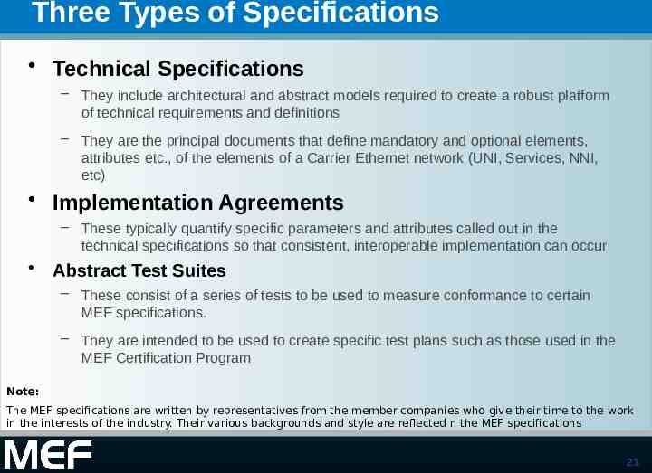
Three Types of Specifications Technical Specifications – They include architectural and abstract models required to create a robust platform of technical requirements and definitions – They are the principal documents that define mandatory and optional elements, attributes etc., of the elements of a Carrier Ethernet network (UNI, Services, NNI, etc) Implementation Agreements – These typically quantify specific parameters and attributes called out in the technical specifications so that consistent, interoperable implementation can occur Abstract Test Suites – These consist of a series of tests to be used to measure conformance to certain MEF specifications. – They are intended to be used to create specific test plans such as those used in the MEF Certification Program Note: The MEF specifications are written by representatives from the member companies who give their time to the work in the interests of the industry. Their various backgrounds and style are reflected n the MEF specifications 21
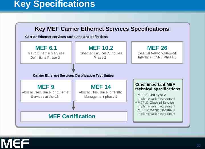
Key Specifications Key MEF Carrier Ethernet Services Specifications Carrier Ethernet services attributes and definitions MEF 6.1 MEF 10.2 MEF 26 Metro Ethernet Services Definitions Phase 2 Ethernet Services Attributes Phase 2 External Network Network Interface (ENNI) Phase 1 Carrier Ethernet Services Certification Test Suites MEF 9 MEF 14 Abstract Test Suite for Ethernet Services at the UNI Abstract Test Suite for Traffic Management phase 1 MEF Certification Other important MEF technical specifications – MEF 20 UNI Type 2 Implementation Agreement – MEF 23 Class of Service Implementation Agreement – MEF 22 Mobile Backhaul Implementation Agreement 22
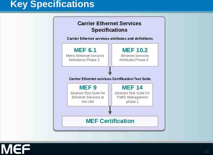
Key Specifications Carrier Ethernet Services Specifications Carrier Ethernet services attributes and definitions MEF 6.1 MEF 10.2 Metro Ethernet Services Definitions Phase 2 Ethernet Services Attributes Phase 2 Carrier Ethernet services Certification Test Suite MEF 9 MEF 14 Abstract Test Suite for Ethernet Services at the UNI Abstract Test Suite for Traffic Management phase 1 MEF Certification 23
Terminology Terminology – There are a great number of definitions in each specification. Where possible they reuse common understanding of terms in other standards bodies such as the ITU – A full glossary of terms used in the MEF Specifications is also available in the Information Center of the MEF Public Web Site Compliance terminology common to all specifications – The level of mandatory and optional compliance to the implementation agreement uses the familiar RFC 2119 terminology 24
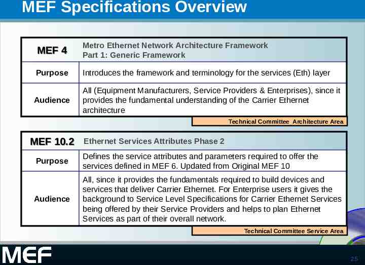
MEF Specifications Overview MEF 4 Metro Ethernet Network Architecture Framework Part 1: Generic Framework Purpose Introduces the framework and terminology for the services (Eth) layer Audience All (Equipment Manufacturers, Service Providers & Enterprises), since it provides the fundamental understanding of the Carrier Ethernet architecture Technical Committee Architecture Area MEF 10.2 Ethernet Services Attributes Phase 2 Purpose Defines the service attributes and parameters required to offer the services defined in MEF 6. Updated from Original MEF 10 Audience All, since it provides the fundamentals required to build devices and services that deliver Carrier Ethernet. For Enterprise users it gives the background to Service Level Specifications for Carrier Ethernet Services being offered by their Service Providers and helps to plan Ethernet Standardized Services as part of their Services overall network. Technical Committee Service Area 25
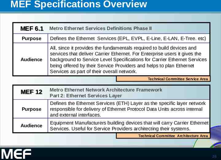
MEF Specifications Overview MEF 6.1 Metro Ethernet Services Definitions Phase II Purpose Defines the Ethernet Services (EPL, EVPL, E-Line, E-LAN, E-Tree. etc) Audience All, since it provides the fundamentals required to build devices and services that deliver Carrier Ethernet. For Enterprise users it gives the background to Service Level Specifications for Carrier Ethernet Services being offered by their Service Providers and helps to plan Ethernet Services as part of their overall network. Technical Committee Service Area MEF 12 Metro Ethernet Network Architecture Framework Part 2: Ethernet Services Layer Purpose Defines the Ethernet Services (ETH) Layer as the specific layer network responsible for delivery of Ethernet Protocol Data Units across internal and external interfaces. Audience Equipment Manufacturers building devices that will carry Carrier Ethernet Services. Useful for Service Providers architecting their systems. Technical Committee Architecture Area 26
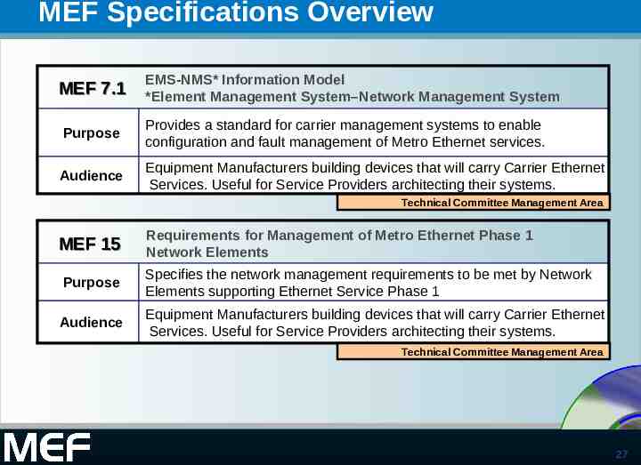
MEF Specifications Overview MEF 7.1 EMS-NMS* Information Model *Element Management System–Network Management System Purpose Provides a standard for carrier management systems to enable configuration and fault management of Metro Ethernet services. Audience Equipment Manufacturers building devices that will carry Carrier Ethernet Services. Useful for Service Providers architecting their systems. Technical Committee Management Area MEF 15 Requirements for Management of Metro Ethernet Phase 1 Network Elements Purpose Specifies the network management requirements to be met by Network Elements supporting Ethernet Service Phase 1 Audience Equipment Manufacturers building devices that will carry Carrier Ethernet Services. Useful for Service Providers architecting their systems. Technical Committee Management Area 27
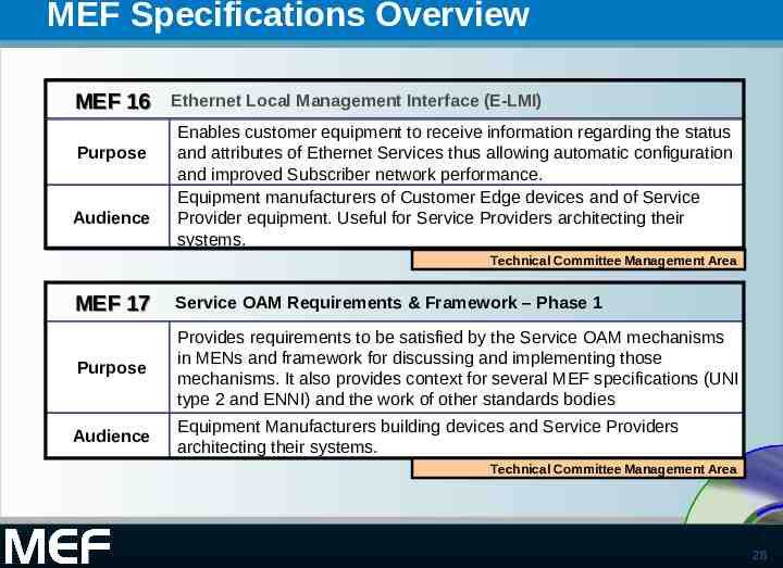
MEF Specifications Overview MEF 16 Purpose Audience Ethernet Local Management Interface (E-LMI) Enables customer equipment to receive information regarding the status and attributes of Ethernet Services thus allowing automatic configuration and improved Subscriber network performance. Equipment manufacturers of Customer Edge devices and of Service Provider equipment. Useful for Service Providers architecting their systems. Technical Committee Management Area MEF 17 Service OAM Requirements & Framework – Phase 1 Purpose Provides requirements to be satisfied by the Service OAM mechanisms in MENs and framework for discussing and implementing those mechanisms. It also provides context for several MEF specifications (UNI type 2 and ENNI) and the work of other standards bodies Audience Equipment Manufacturers building devices and Service Providers architecting their systems. Technical Committee Management Area 28
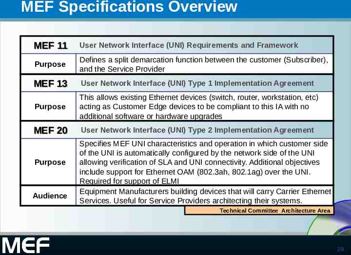
MEF Specifications Overview MEF 11 User Network Interface (UNI) Requirements and Framework Purpose Defines a split demarcation function between the customer (Subscriber), and the Service Provider MEF 13 User Network Interface (UNI) Type 1 Implementation Agreement Purpose This allows existing Ethernet devices (switch, router, workstation, etc) acting as Customer Edge devices to be compliant to this IA with no additional software or hardware upgrades MEF 20 User Network Interface (UNI) Type 2 Implementation Agreement Purpose Audience Specifies MEF UNI characteristics and operation in which customer side of the UNI is automatically configured by the network side of the UNI allowing verification of SLA and UNI connectivity. Additional objectives include support for Ethernet OAM (802.3ah, 802.1ag) over the UNI. Required for support of ELMI Equipment Manufacturers building devices that will carry Carrier Ethernet Services. Useful for Service Providers architecting their systems. Technical Committee Architecture Area 29
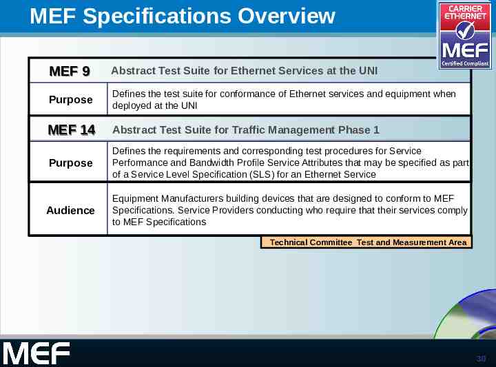
MEF Specifications Overview MEF 9 Abstract Test Suite for Ethernet Services at the UNI Purpose Defines the test suite for conformance of Ethernet services and equipment when deployed at the UNI MEF 14 Abstract Test Suite for Traffic Management Phase 1 Purpose Defines the requirements and corresponding test procedures for Service Performance and Bandwidth Profile Service Attributes that may be specified as part of a Service Level Specification (SLS) for an Ethernet Service Audience Equipment Manufacturers building devices that are designed to conform to MEF Specifications. Service Providers conducting who require that their services comply to MEF Specifications Technical Committee Test and Measurement Area 30
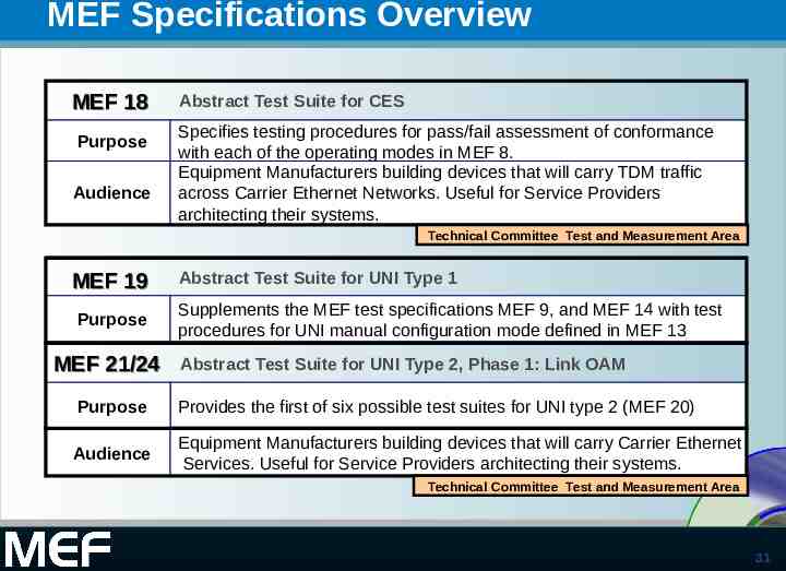
MEF Specifications Overview MEF 18 Purpose Audience Abstract Test Suite for CES Specifies testing procedures for pass/fail assessment of conformance with each of the operating modes in MEF 8. Equipment Manufacturers building devices that will carry TDM traffic across Carrier Ethernet Networks. Useful for Service Providers architecting their systems. Technical Committee Test and Measurement Area MEF 19 Purpose MEF 21/24 Abstract Test Suite for UNI Type 1 Supplements the MEF test specifications MEF 9, and MEF 14 with test procedures for UNI manual configuration mode defined in MEF 13 Abstract Test Suite for UNI Type 2, Phase 1: Link OAM Purpose Provides the first of six possible test suites for UNI type 2 (MEF 20) Audience Equipment Manufacturers building devices that will carry Carrier Ethernet Services. Useful for Service Providers architecting their systems. Technical Committee Test and Measurement Area 31
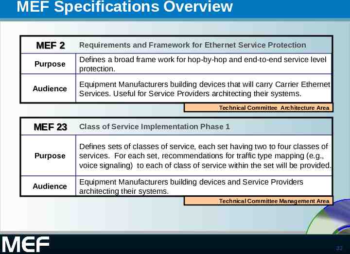
MEF Specifications Overview MEF 2 Requirements and Framework for Ethernet Service Protection Purpose Defines a broad frame work for hop-by-hop and end-to-end service level protection. Audience Equipment Manufacturers building devices that will carry Carrier Ethernet Services. Useful for Service Providers architecting their systems. Technical Committee Architecture Area MEF 23 Class of Service Implementation Phase 1 Purpose Defines sets of classes of service, each set having two to four classes of services. For each set, recommendations for traffic type mapping (e.g., voice signaling) to each of class of service within the set will be provided. Audience Equipment Manufacturers building devices and Service Providers architecting their systems. Technical Committee Management Area 32
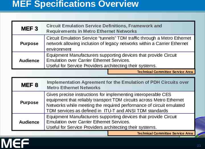
MEF Specifications Overview MEF 3 Purpose Audience Circuit Emulation Service Definitions, Framework and Requirements in Metro Ethernet Networks Circuit Emulation Service “tunnels” TDM traffic through a Metro Ethernet network allowing inclusion of legacy networks within a Carrier Ethernet environment Equipment Manufacturers supporting devices that provide Circuit Emulation over Carrier Ethernet Services. Useful for Service Providers architecting their systems. Technical Committee Service Area MEF 8 Purpose Audience Implementation Agreement for the Emulation of PDH Circuits over Metro Ethernet Networks Gives precise instructions for implementing interoperable CES equipment that reliably transport TDM circuits across Metro Ethernet Networks while meeting the required performance of circuit emulated TDM services as defined in ITU-T and ANSI TDM standards Equipment Manufacturers supporting devices that provide Circuit Emulation over Carrier Ethernet Services. Useful for Service Providers architecting their systems. Technical Committee Service Area 33
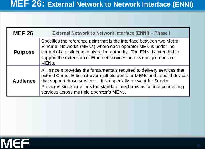
MEF 26: External Network to Network Interface (ENNI) MEF 26 External Network to Network Interface (ENNI) – Phase I Purpose Specifies the reference point that is the interface between two Metro Ethernet Networks (MENs) where each operator MEN is under the control of a distinct administration authority. The ENNI is intended to support the extension of Ethernet services across multiple operator MENs. Audience All, since it provides the fundamentals required to delivery services that extend Carrier Ethernet over multiple operator MENs and to build devices that support those services . It is especially relevant for Service Providers since it defines the standard mechanisms for interconnecting Standardized services across multiple operator’s MENs. Services 34
Recently Approved Specifications 35
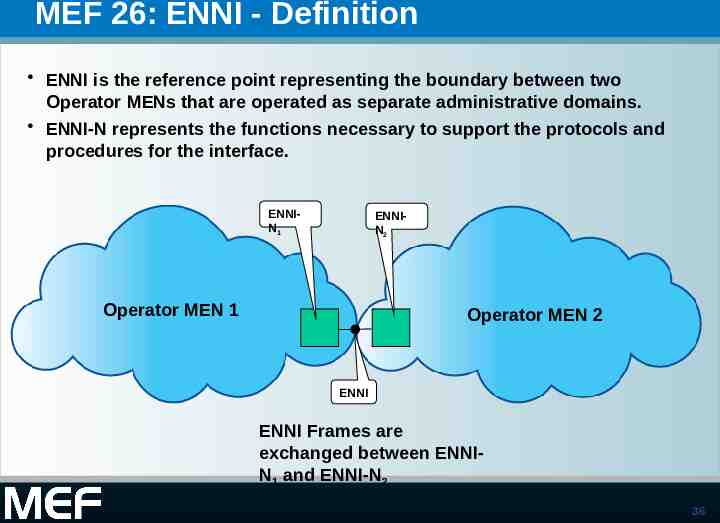
MEF 26: ENNI - Definition ENNI is the reference point representing the boundary between two Operator MENs that are operated as separate administrative domains. ENNI-N represents the functions necessary to support the protocols and procedures for the interface. ENNIN1 ENNIN2 Operator MEN 1 Operator MEN 2 ENNI ENNI Frames are exchanged between ENNIN1 and ENNI-N2 36
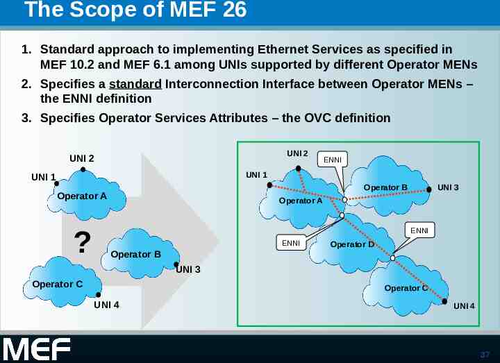
The Scope of MEF 26 1. Standard approach to implementing Ethernet Services as specified in MEF 10.2 and MEF 6.1 among UNIs supported by different Operator MENs 2. Specifies a standard Interconnection Interface between Operator MENs – the ENNI definition 3. Specifies Operator Services Attributes – the OVC definition UNI 2 UNI 2 ENNI UNI 1 UNI 1 Operator B Operator A ? UNI 3 Operator A ENNI ENNI Operator B Operator D UNI 3 Operator C Operator C UNI 4 UNI 4 37
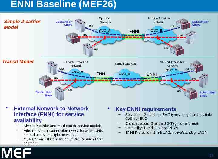
ENNI Baseline (MEF26) Simple 2-carrier Model Service Provider Network Operator Network Subscriber Sites UNI UNI OVC A ENNI UNI OVC B UNI UNI UNI Transit Model Service Provider 1 Network UNI OVC A Subscriber Sites Service Provider 2 Network Transit Operator ENNI OVC B ENNI OVC C UNI Subscriber Sites UNI UNI External Network-to-Network Interface (ENNI) for service availability – – – UNI Simple 2-carrier and multi-carrier service models Ethernet Virtual Connection (EVC) between UNIs spread across multiple networks Operator Virtual Connection (OVC) for each EVC segment UNI Subscriber Sites Key ENNI requirements – – – – Services: p2p and mp EVC types, single and multiple CoS per EVC Encapsulation: Standard S-Tag frame format Scalability: 1 and 10 Gbps PHYs ENNI Protection: 2-link LAG, active/standby, LACP 38
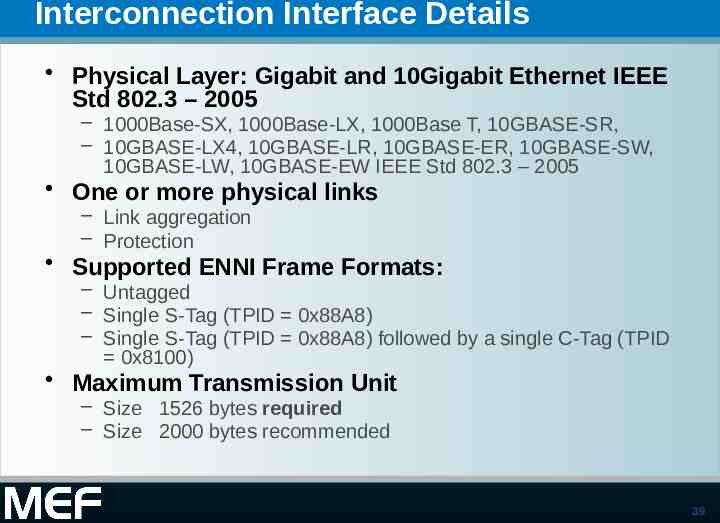
Interconnection Interface Details Physical Layer: Gigabit and 10Gigabit Ethernet IEEE Std 802.3 – 2005 – 1000Base-SX, 1000Base-LX, 1000Base T, 10GBASE-SR, – 10GBASE-LX4, 10GBASE-LR, 10GBASE-ER, 10GBASE-SW, 10GBASE-LW, 10GBASE-EW IEEE Std 802.3 – 2005 One or more physical links – Link aggregation – Protection Supported ENNI Frame Formats: – Untagged – Single S-Tag (TPID 0x88A8) – Single S-Tag (TPID 0x88A8) followed by a single C-Tag (TPID 0x8100) Maximum Transmission Unit – Size 1526 bytes required – Size 2000 bytes recommended 39
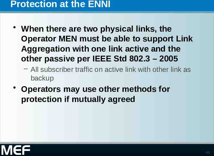
Protection at the ENNI When there are two physical links, the Operator MEN must be able to support Link Aggregation with one link active and the other passive per IEEE Std 802.3 – 2005 – All subscriber traffic on active link with other link as backup Operators may use other methods for protection if mutually agreed 40
Management at the ENNI The Operator MEN must be able to support Link OAM as per IEEE Std 802.3 – 2005 However it is recommended that the loopback capability be disabled 41
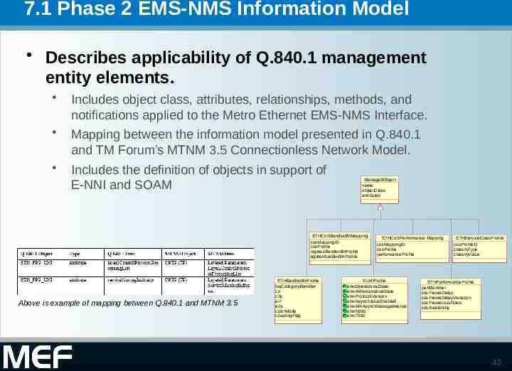
7.1 Phase 2 EMS-NMS Information Model Describes applicability of Q.840.1 management entity elements. Includes object class, attributes, relationships, methods, and notifications applied to the Metro Ethernet EMS-NMS Interface. Mapping between the information model presented in Q.840.1 and TM Forum’s MTNM 3.5 Connectionless Network Model. Includes the definition of objects in support of E-NNI and SOAM ManagedObject name objectClass attributes ETHCoSBandwidthMapping cosMappingID cosProfile ingressBandwidthProfile egressBandwidthProfile Above is example of mapping between Q.840.1 and MTNM 3.5 ETHBandwidthProfile bwCategoryIdentifier cir cbs eir ebs colorMode couplingFlag ETHCoSPerformance Mapping cosMappingID cosProfile performanceProfile ELMIProfile elmiOperationalState elmiAdministrativeState elmiProtocolVersion elmiAsyncStatusEnabled elmiMinAsyncMessageInterval elmiN393 elmiT392 ETHServiceClassProfile cosProfileID classifyType classifyValue ETHPerformanceProfile perfIdentifier cosFrameDelay cosFrameDelayVariation cosFrameLossRatio cosAvailability 42
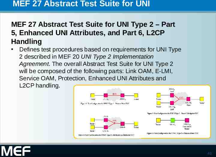
MEF 27 Abstract Test Suite for UNI MEF 27 Abstract Test Suite for UNI Type 2 – Part 5, Enhanced UNI Attributes, and Part 6, L2CP Handling Defines test procedures based on requirements for UNI Type 2 described in MEF 20 UNI Type 2 Implementation Agreement. The overall Abstract Test Suite for UNI Type 2 will be composed of the following parts: Link OAM, E-LMI, Service OAM, Protection, Enhanced UNI Attributes and L2CP handling. 43
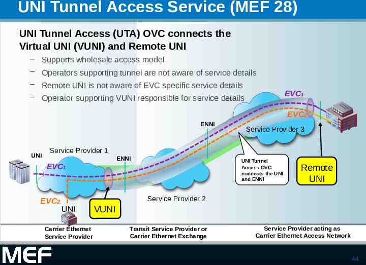
UNI Tunnel Access Service (MEF 28) UNI Tunnel Access (UTA) OVC connects the Virtual UNI (VUNI) and Remote UNI – Supports wholesale access model – Operators supporting tunnel are not aware of service details – Remote UNI is not aware of EVC specific service details – Operator supporting VUNI responsible for service details EVC1 EVC2 ENNI UNI Service Provider 3 Service Provider 1 ENNI EVC1 EVC2 UNI Tunnel Access OVC connects the UNI and ENNI Remote UNI Service Provider 2 UNI Carrier Ethernet Service Provider VUNI Transit Service Provider or Carrier Ethernet Exchange Service Provider acting as Carrier Ethernet Access Network 44
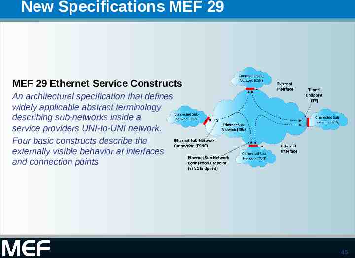
New Specifications MEF 29 MEF 29 Ethernet Service Constructs An architectural specification that defines widely applicable abstract terminology describing sub-networks inside a service providers UNI-to-UNI network. Four basic constructs describe the externally visible behavior at interfaces and connection points 45
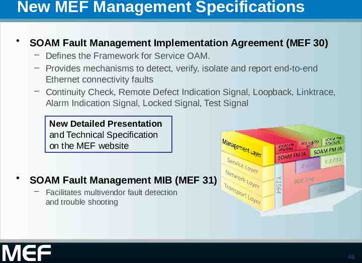
New MEF Management Specifications SOAM Fault Management Implementation Agreement (MEF 30) – Defines the Framework for Service OAM. – Provides mechanisms to detect, verify, isolate and report end-to-end Ethernet connectivity faults – Continuity Check, Remote Defect Indication Signal, Loopback, Linktrace, Alarm Indication Signal, Locked Signal, Test Signal New Detailed Presentation and Technical Specification on the MEF website SOAM Fault Management MIB (MEF 31) – Facilitates multivendor fault detection and trouble shooting 46
Active Projects 47
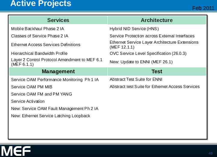
Active Projects Services Feb 2011 Architecture Mobile Backhaul Phase 2 IA Hybrid NID Service (HNS) Classes of Service Phase 2 IA Service Protection across External Interfaces Ethernet Service Layer Architecture Extensions (MEF 12.1.1) OVC Service Level Specification (26.0.3) Ethernet Access Services Definitions Hierarchical Bandwidth Profile Layer 2 Control Protocol Amendment to MEF 6.1 (MEF 6.1.1) Management New: Update to ENNI (MEF 26.1) Test Service OAM Performance Monitoring Ph 1 IA Abstract Test Suite for ENNI Service OAM PM MIB Abstract test Suite for Ethernet Access Services Service OAM FM and PM YANG Service Activation New: Service OAM Fault Management Ph 2 IA New: Ethernet Service Latching Loopback 48
Architecture Projects 49
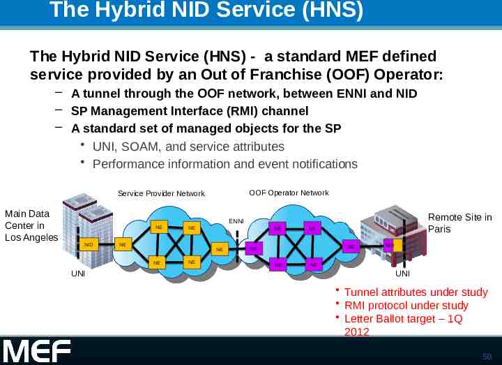
The Hybrid NID Service (HNS) The Hybrid NID Service (HNS) - a standard MEF defined service provided by an Out of Franchise (OOF) Operator: – A tunnel through the OOF network, between ENNI and NID – SP Management Interface (RMI) channel – A standard set of managed objects for the SP UNI, SOAM, and service attributes Performance information and event notifications OOF Operator Network Service Provider Network Main Data Center in Los Angeles NE NID UNI NE NE NE NE NE Remote Site in Paris ENNI NE NE NE NE NE NID NE UNI Tunnel attributes under study RMI protocol under study Letter Ballot target – 1Q 2012 50
Management Projects 51
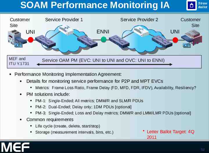
SOAM Performance Monitoring IA Customer Site UNI Service Provider 1 Service Provider 2 ENNI CE CE MEF and ITU Y.1731 Straw Ballot Customer Site UNI CE CE Service OAM PM (EVC: UNI to UNI and OVC: UNI to ENNI) Performance Monitoring Implementation Agreement: Details for monitoring service performance for P2P and MPT EVCs Metrics: Frame Loss Ratio, Frame Delay (FD, MFD, FDR, IFDV), Availability, Resiliency? PM solutions include: PM-1: Single-Ended; All metrics; DMM/R and SLM/R PDUs PM-2: Dual-Ended; Delay only; 1DM PDUs [optional] PM-3: Single-Ended; Loss and Delay metrics; DMM/R and LMM/LMR PDUs [optional] Common requirements Life cycle (create, delete, start/stop) Letter Ballot Target: 4Q Storage (measurement intervals, bins, etc.) 2011 52
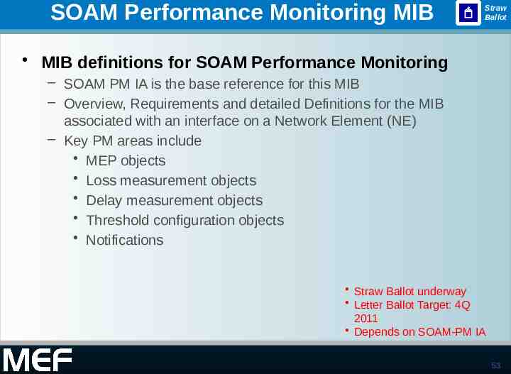
SOAM Performance Monitoring MIB Straw Ballot MIB definitions for SOAM Performance Monitoring – SOAM PM IA is the base reference for this MIB – Overview, Requirements and detailed Definitions for the MIB associated with an interface on a Network Element (NE) – Key PM areas include MEP objects Loss measurement objects Delay measurement objects Threshold configuration objects Notifications Straw Ballot underway Letter Ballot Target: 4Q 2011 Depends on SOAM-PM IA 53
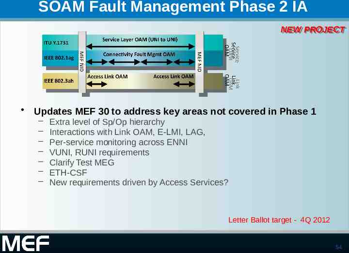
SOAM Fault Management Phase 2 IA NEW NEW PROJECT PROJECT Updates MEF 30 to address key areas not covered in Phase 1 – – – – – – – Extra level of Sp/Op hierarchy Interactions with Link OAM, E-LMI, LAG, Per-service monitoring across ENNI VUNI, RUNI requirements Clarify Test MEG ETH-CSF New requirements driven by Access Services? Letter Ballot target - 4Q 2012 54
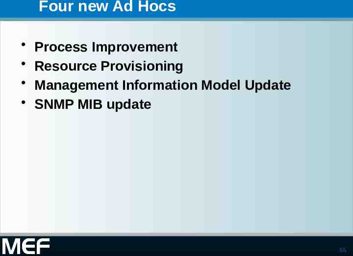
Four new Ad Hocs Process Improvement Resource Provisioning Management Information Model Update SNMP MIB update 55
Services Projects 56
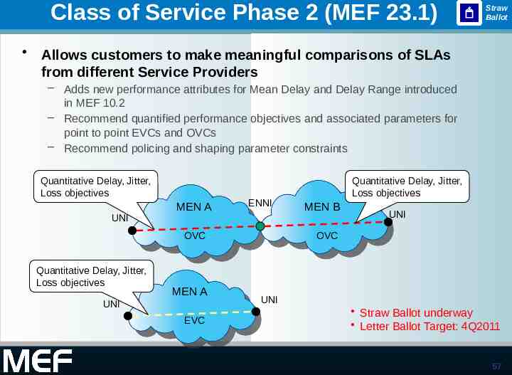
Class of Service Phase 2 (MEF 23.1) Straw Ballot Allows customers to make meaningful comparisons of SLAs from different Service Providers – Adds new performance attributes for Mean Delay and Delay Range introduced in MEF 10.2 – Recommend quantified performance objectives and associated parameters for point to point EVCs and OVCs – Recommend policing and shaping parameter constraints Quantitative Delay, Jitter, Loss objectives UNI MEN A ENNI OVC Quantitative Delay, Jitter, Loss objectives UNI MEN A EVC Quantitative Delay, Jitter, Loss objectives MEN B UNI OVC UNI Straw Ballot underway Letter Ballot Target: 4Q2011 57
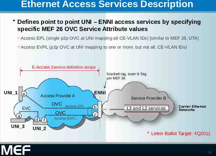
Ethernet Access Services Description Defines point to point UNI – ENNI access services by specifying specific MEF 26 OVC Service Attribute values – Access EPL (single p2p OVC at UNI mapping all CE-VLAN IDs) [similar to MEF 28, UTA] – Access EVPL (p2p OVC at UNI mapping to one or more, but not all, CE-VLAN IDs) E-Access Service definition scope Stacked tag, outer S-Tag per MEF 26 UNI 1 e Access Provider A OVC EVC a UNI 3 Access EPL OVC d f UNI 2 Access EVPL ENNI Service Provider B b L3 L3 and and L2 L2 services services Carrier Ethernet Networks c Letter Ballot Target: 4Q2011 58
External Interface Service Protection Letter Ballot Specification of the MEF requirements for Service Protection across External Interfaces (ENNI, UNI) Requirements Addressing this area MEN Interconnected Zone Interconnected Zone MEN MEN Requirements Addressing this area Letter Ballot now 59
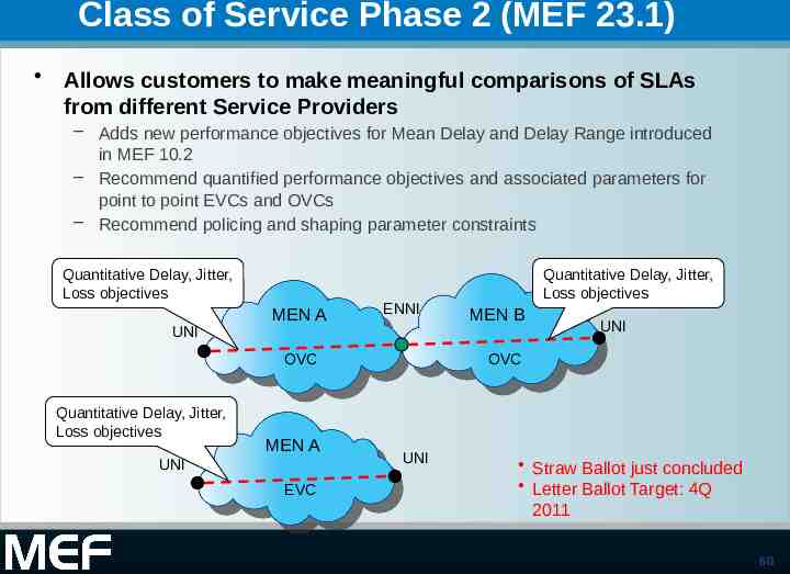
Class of Service Phase 2 (MEF 23.1) Allows customers to make meaningful comparisons of SLAs from different Service Providers – Adds new performance objectives for Mean Delay and Delay Range introduced in MEF 10.2 – Recommend quantified performance objectives and associated parameters for point to point EVCs and OVCs – Recommend policing and shaping parameter constraints Quantitative Delay, Jitter, Loss objectives UNI MEN A ENNI OVC Quantitative Delay, Jitter, Loss objectives UNI MEN A EVC Quantitative Delay, Jitter, Loss objectives MEN B UNI OVC UNI Straw Ballot just concluded Letter Ballot Target: 4Q 2011 60
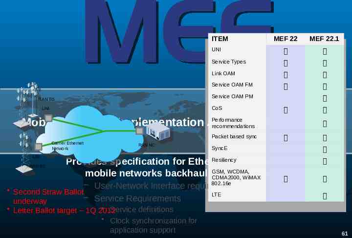
ITEM MEF 22 MEF 22.1 UNI Service Types Link OAM Service OAM FM Service OAM PM RAN BS CoS UNI Performance Mobile Backhaul Implementation Agreement (MEF 22.1) recommendations UNI Packet based sync Carrier Ethernet Network UNI RAN BS RAN NC SyncE Resiliency Provides specification for Ethernet services for GSM, WCDMA, mobile networks backhaul (2G, 3G, 4G) CDMA2000, WiMAX 802.16e – User-Network Interface requirements Second Straw Ballot LTE – Service Requirements underway Service definitions Letter Ballot target – 1Q 2012 Clock synchronization for application support 61
Testing Projects 62
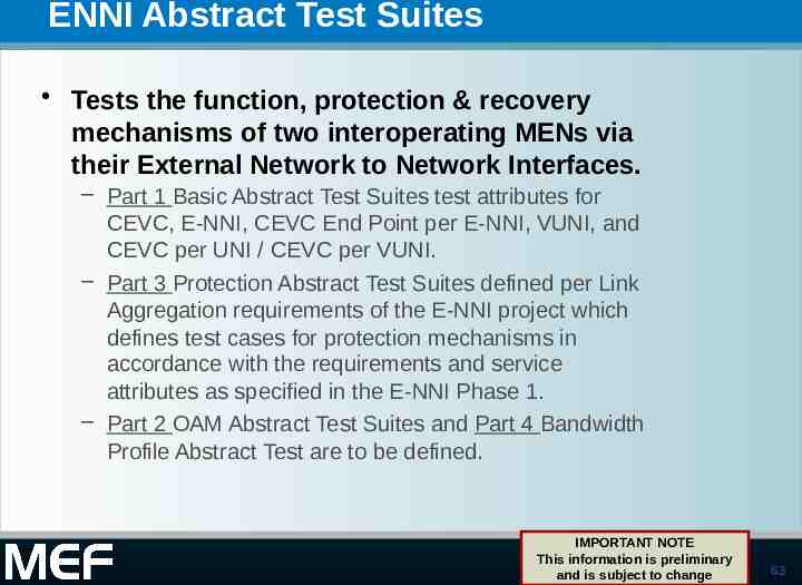
ENNI Abstract Test Suites Tests the function, protection & recovery mechanisms of two interoperating MENs via their External Network to Network Interfaces. – Part 1 Basic Abstract Test Suites test attributes for CEVC, E-NNI, CEVC End Point per E-NNI, VUNI, and CEVC per UNI / CEVC per VUNI. – Part 3 Protection Abstract Test Suites defined per Link Aggregation requirements of the E-NNI project which defines test cases for protection mechanisms in accordance with the requirements and service attributes as specified in the E-NNI Phase 1. – Part 2 OAM Abstract Test Suites and Part 4 Bandwidth Profile Abstract Test are to be defined. IMPORTANT NOTE This information is preliminary and is subject to change 63
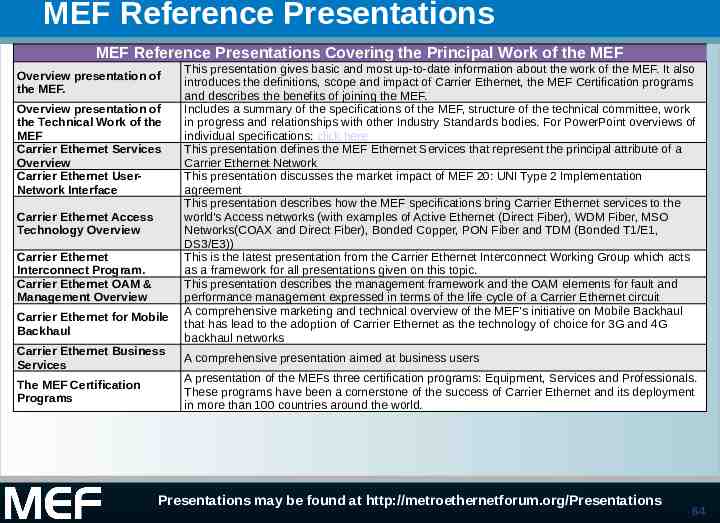
MEF Reference Presentations MEF Reference Presentations Covering the Principal Work of the MEF Overview presentation of the MEF. Overview presentation of the Technical Work of the MEF Carrier Ethernet Services Overview Carrier Ethernet UserNetwork Interface Carrier Ethernet Access Technology Overview Carrier Ethernet Interconnect Program. Carrier Ethernet OAM & Management Overview Carrier Ethernet for Mobile Backhaul This presentation gives basic and most up-to-date information about the work of the MEF. It also introduces the definitions, scope and impact of Carrier Ethernet, the MEF Certification programs and describes the benefits of joining the MEF. Includes a summary of the specifications of the MEF, structure of the technical committee, work in progress and relationships with other Industry Standards bodies. For PowerPoint overviews of individual specifications: click here This presentation defines the MEF Ethernet Services that represent the principal attribute of a Carrier Ethernet Network This presentation discusses the market impact of MEF 20: UNI Type 2 Implementation agreement This presentation describes how the MEF specifications bring Carrier Ethernet services to the world's Access networks (with examples of Active Ethernet (Direct Fiber), WDM Fiber, MSO Networks(COAX and Direct Fiber), Bonded Copper, PON Fiber and TDM (Bonded T1/E1, DS3/E3)) This is the latest presentation from the Carrier Ethernet Interconnect Working Group which acts as a framework for all presentations given on this topic. This presentation describes the management framework and the OAM elements for fault and performance management expressed in terms of the life cycle of a Carrier Ethernet circuit A comprehensive marketing and technical overview of the MEF's initiative on Mobile Backhaul that has lead to the adoption of Carrier Ethernet as the technology of choice for 3G and 4G backhaul networks Carrier Ethernet Business Services A comprehensive presentation aimed at business users The MEF Certification Programs A presentation of the MEFs three certification programs: Equipment, Services and Professionals. These programs have been a cornerstone of the success of Carrier Ethernet and its deployment in more than 100 countries around the world. Presentations may be found at http://metroethernetforum.org/Presentations 64
End of Presentation 65 65