A Combat Support Agency Defense Information Systems Agency A Combat


11 Slides492.63 KB
A Combat Support Agency Defense Information Systems Agency A Combat Support Agency Model Based Systems Engineering and Systems Modeling Language DoDAF Plenary January 5, 2012 Chris Gedo Chief, Architecture Branch Enterprise Engineering Directorate [email protected]
Overview A Combat Support Agency Motivation Model Based Systems Engineering (MBSE) Overview Architecting with MBSE Systems Modeling Language (SysML) relationship to the DoD Architecture Framework (DoDAF) DISA’s transition to MBSE & SysML 2
Motivation A Combat Support Agency Develop an integrated architecture for critical portions of the Global Information Grid (GIG) – Comprehensive Includes all essential capabilities Applies to all DoD Components – Based on rigorous Systems Engineering principles Such as those espoused by DoD 5000, INCOSE, etc. Traditional development practices have not produced the desired results for complex, large scale IT problems – Current artifacts do not routinely address critical analysis details Imprecise descriptions lead to different interpretations of the artifacts – Focus is on generating artifacts rather than the underlying data Improved techniques could facilitate better analysis We Need to Understand How Systems Work 3
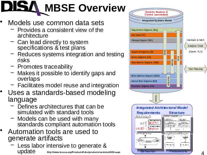
Support Agency A Combat Models use common data sets Use Cases [UC] Interface to M&S Package Diagram [PKG] Analysis Tools Sequence Diagrams [SD] (Opnet, XLS) Activity Diagrams [AD] Allocate State Machine Diagrams [SMD] Test Planning Block Definition Diagrams [BDD] Internal Block Diagrams [IBD] Parametric Diagrams [PD] Value Build – Defines architectures that can be simulated with standard tools – Models can be used with many standards compliant automation tools Requirements Diagrams [Req] Output Uses a standards-based modeling language Integrated Systems Model Satisfy – Provides a consistent view of the architecture – Can lead directly to system specifications & test plans – Reduces systems integration and testing risks – Promotes traceability – Makes it possible to identify gaps and overlaps – Facilitates model reuse and integration Systems Analysis & Control (automated) Verify MBSE Overview Integrated Architectural Model Requirements Structure Automation tools are used to generate artifacts – Less labor intensive to generate & update http://www.incose.org/ProductsPubs/products/sevision2020.aspx Behavior Parametric 4
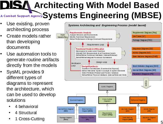
Architecting With Model Based Systems Engineering (MBSE) A Combat Support Agency Use existing, proven Systems Architecting and Engineering Process (model based) architecting process Requirements Diagrams [Req] Requirements Analysis Input Use Cases [UC] Create models rather Needs/Req Package Diagram [PKG] than developing Requirements Loop documents Sequence Diagrams [SD] Functional Analysis/Allocation Activity Diagrams [AD] Use automation tools to State Machine Diagrams [SMD] generate routine artifacts Design Loop Verification Loop directly from the models Block Definition Diagrams [BDD] Design/Synthesis Internal Block Diagrams [IBD] SysML provides 9 Parametric Diagrams [PD] different types of diagrams to represent the architecture, which can be used to develop solutions Analyze Missions and Environments Identify Functional Requirements Define Performance & Design Constraint Requirements Decompose to Lower-Level Functions Allocate Perf. Requirements to all Functional Levels Define/Refine Functional Interfaces (Internal/External) Define/Refine/Integrate Functional Architecture Transform Architectures (Functional to Physical) Define Alternative System Concepts & System Elements Select Preferred Product and Process Solutions Define/Refine Physical Interfaces (Internal/External) Verify Output SysML Diagrams Structural Diagrams 4 behavioral 4 Structural 1 Cross-Cutting Internal Block Diagram [IBD] Cross-Cutting Diagrams Block Definition Diagram [BDD] Behavioral Diagrams Use Case Diagram [UC] Activity Diagram [AD] State Machine Diagram [SMD] Sequence Diagram [SD] Requirements Diagram [REQ] Package Diagram [PKG] Parametric Diagram [PD] 5
Systems Modeling Language A Combat Support Agency http://www.omg.org/cgi-bin/doc?dtc/2001-07-02 International Council on Systems Engineering (INCOSE) defined the Unified Modeling Language (UML) for Systems Engineering strategy in January 2001 INCOSE partnered with the Object Management Group (OMG) in July 2001 to develop the language OMG published Systems Modeling Language (SysML) version 1.0 specification in June 2006 SysML v1.0 specification defines 9 types of diagrams that map directly to DoDAF models Reports can be generated from the SysML models that are consistent with DoDAF matrix artifacts 6
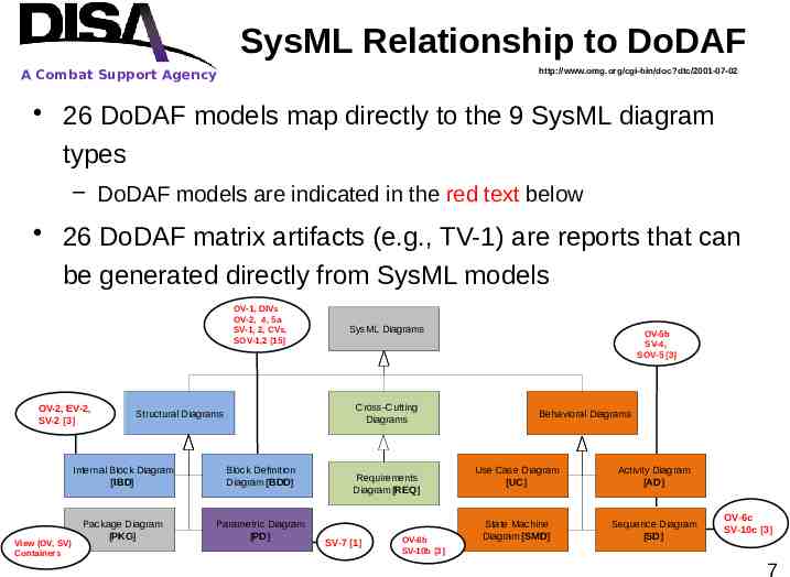
SysML Relationship to DoDAF http://www.omg.org/cgi-bin/doc?dtc/2001-07-02 A Combat Support Agency 26 DoDAF models map directly to the 9 SysML diagram types – DoDAF models are indicated in the red text below 26 DoDAF matrix artifacts (e.g., TV-1) are reports that can be generated directly from SysML models OV-1, DIVs OV-2, 4, 5a SV-1, 2, CVs, SOV-1,2 [15] OV-2, EV-2, SV-2 [3] View (OV, SV) Containers SysML Diagrams Cross-Cutting Diagrams Structural Diagrams Internal Block Diagram [IBD] Block Definition Diagram [BDD] Package Diagram [PKG] Parametric Diagram [PD] Requirements Diagram [REQ] SV-7 [1] OV-6b SV-10b [3] OV-5b SV-4, SOV-5 [3] Behavioral Diagrams Use Case Diagram [UC] Activity Diagram [AD] State Machine Diagram [SMD] Sequence Diagram [SD] OV-6c SV-10c [3] 7
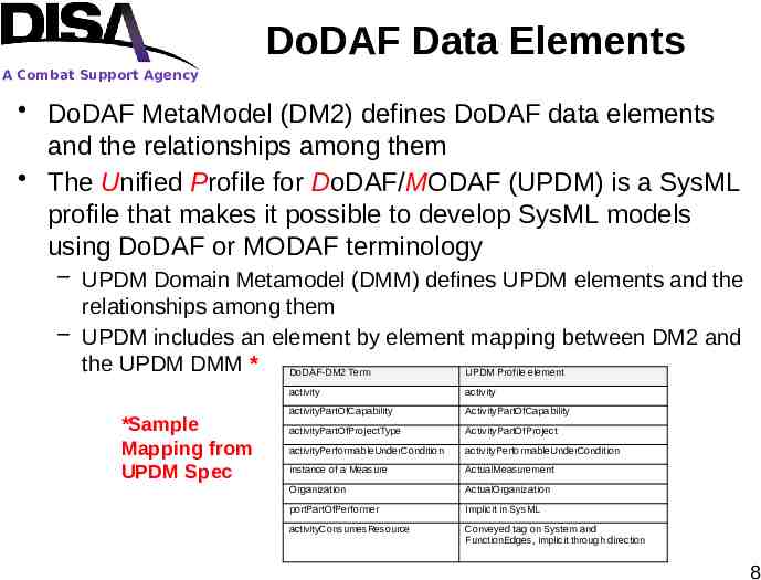
DoDAF Data Elements A Combat Support Agency DoDAF MetaModel (DM2) defines DoDAF data elements and the relationships among them The Unified Profile for DoDAF/MODAF (UPDM) is a SysML profile that makes it possible to develop SysML models using DoDAF or MODAF terminology – UPDM Domain Metamodel (DMM) defines UPDM elements and the relationships among them – UPDM includes an element by element mapping between DM2 and the UPDM DMM * DoDAF-DM2 Term UPDM Profile element *Sample Mapping from UPDM Spec activity activity activityPartOfCapability ActivityPartOfCapability activityPartOfProjectType ActivityPartOfProject activityPerformableUnderCondition activityPerformableUnderCondition instance of a Measure ActualMeasurement Organization ActualOrganization portPartOfPerformer Implicit in SysML activityConsumesResource Conveyed tag on System and FunctionEdges, implicit through direction 8
DISA’s Transition to MBSE A Combat Support Agency Actions to date – Trained the Enterprise Engineering staff on MBSE/SysML – Updating our internal systems engineering processes – Developing a common data structure so that models representing individual capabilities can be integrated – Developed a standard template for documenting DISA capabilities – Completed initial set of pilot projects to produce models & SysML artifacts for the 2012 version of the GIG Convergence Master Plan (GCMP) Planned actions – Transition remaining DISA programs & projects – Update future versions of the GCMP with SysML artifacts – Continue training DISA & DoD personnel – Develop all new capabilities using MBSE 9
A Combat Support Agency Questions? Thank you for your attention 10
A Combat Support Agency www.disa.mil