Module 9 – Thévenin and Norton Equivalent Circuits In this


36 Slides1.09 MB
Module 9 - Thévenin and Norton Equivalent Circuits In this module, we’ll learn about an important property of resistive circuits called Thévenin Equivalence. M. Leon Thévenin (1857-1926), published his famous theorem in 1883. 1
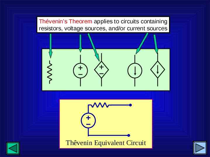
Thévenin’s Theorem applies to circuits containing resistors, voltage sources, and/or current sources Thêvenin Equivalent Circuit 2
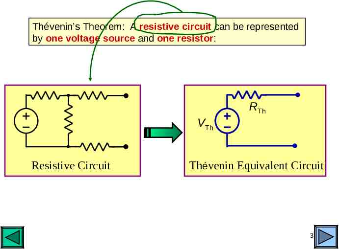
Thévenin’s Theorem: A resistive circuit can be represented by one voltage source and one resistor: RTh VTh Resistive Circuit Thévenin Equivalent Circuit 3
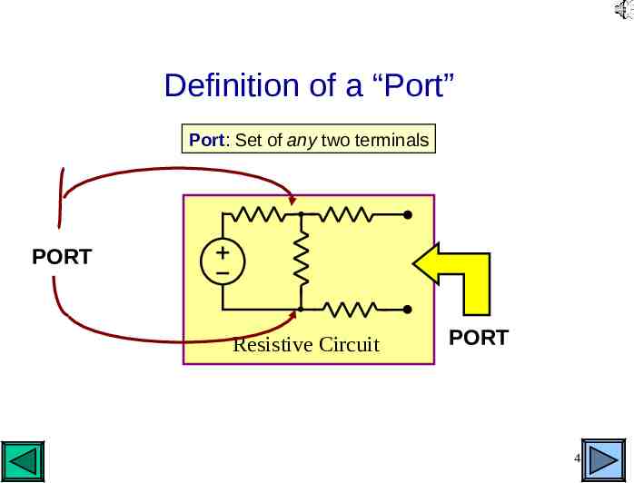
Definition of a “Port” Port: Set of any two terminals PORT Resistive Circuit PORT 4
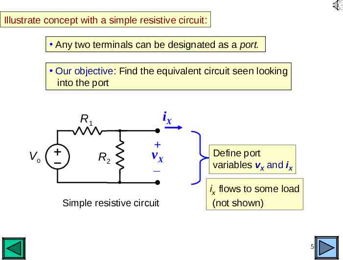
Illustrate concept with a simple resistive circuit: Any two terminals can be designated as a port. Our objective: Find the equivalent circuit seen looking into the port iX R1 Vo R2 vX Simple resistive circuit Define port variables vX and iX ix flows to some load (not shown) 5
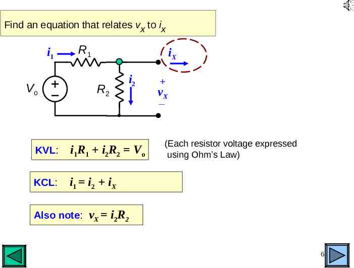
Find an equation that relates vx to ix i1 Vo R1 iX R2 i2 KVL: i1R1 i2R2 Vo KCL: i1 i 2 iX vX (Each resistor voltage expressed using Ohm’s Law) Also note: vX i2R2 6
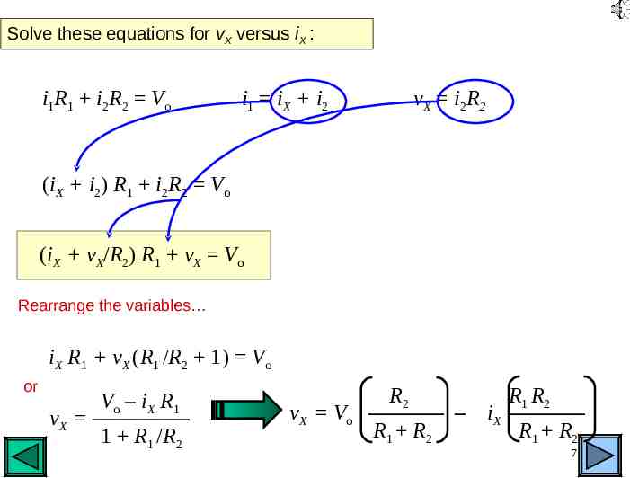
Solve these equations for vX versus iX : i1R1 i2R2 Vo i1 i X i2 vX i2R2 (iX i2) R1 i2R2 Vo (iX vX/R2) R1 vX Vo Rearrange the variables iX R1 vX (R1 /R2 1) Vo or Vo – iX R1 vX ––––––––– 1 R1 /R2 vX Vo R2 R1 R2 ––––––– – iX ––––––– R1 R2 R1 R2 7
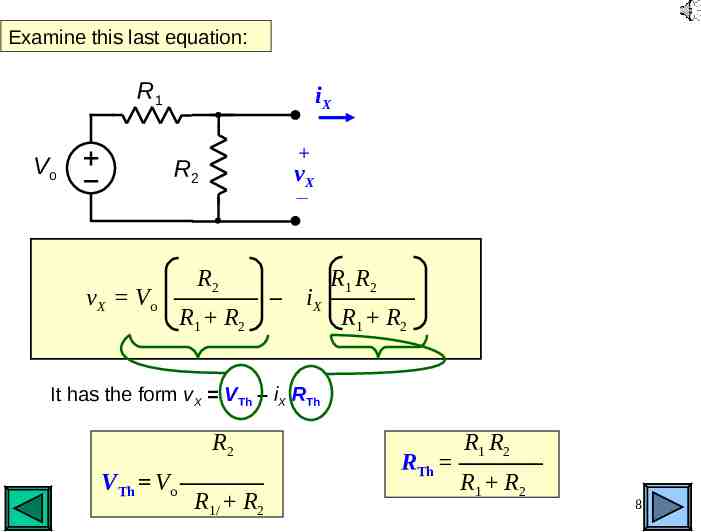
Examine this last equation: R1 Vo iX R2 vX V o vX R2 R1 R2 ––––––– – iX ––––––– R1 R2 R1 R2 It has the form vX VTh – iX RTh R2 VTh Vo ––––––– R1/ R2 R1 R2 RTh ––––––– R1 R2 8
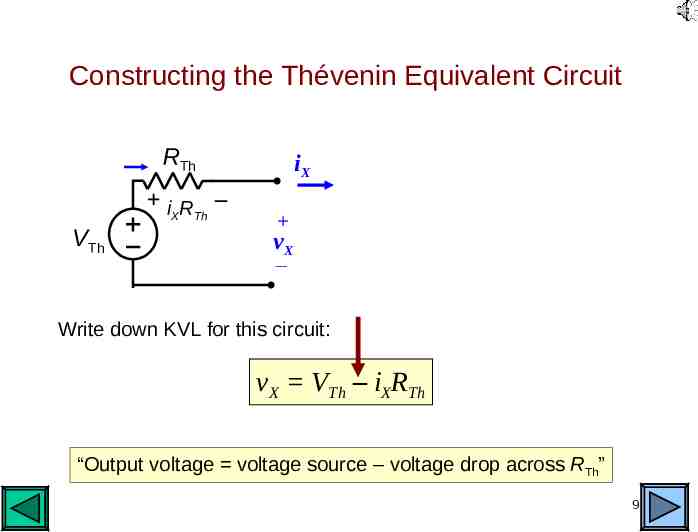
Constructing the Thévenin Equivalent Circuit RTh i R – X Th VTh iX vX Write down KVL for this circuit: vX VTh – iXRTh “Output voltage voltage source – voltage drop across RTh” 9
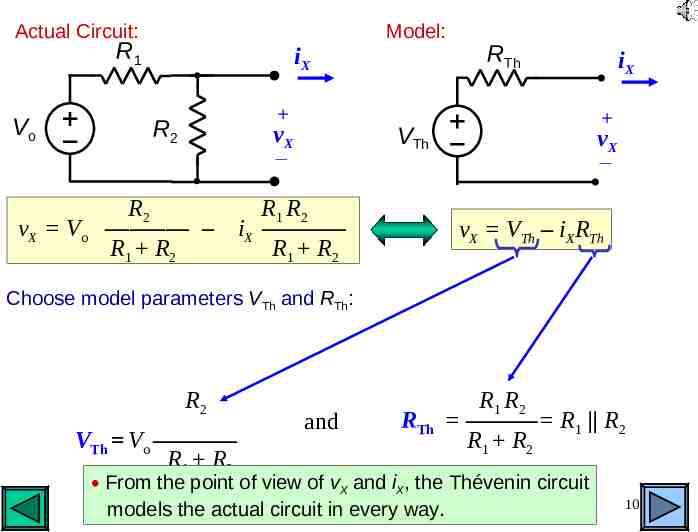
Actual Circuit: R1 Vo iX R2 vX Vo vX Model: RTh VTh iX vX R2 R1 R2 ––––––– – iX ––––––– R1 R2 R1 R2 vX VTh – iXRTh Choose model parameters VTh and RTh: R2 and RTh R1 R2 –––––– R1 R2 R1 R2 VTh Vo ––––––– R1 R2 From the point of view of vX and iX, the Thévenin circuit models the actual circuit in every way. 10
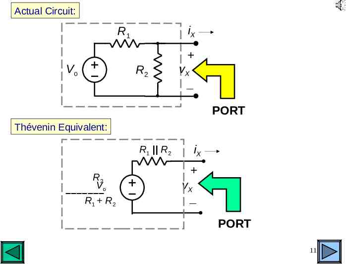
Actual Circuit: iX R1 Vo R2 vX PORT Thévenin Equivalent: R1 R2 R2 V –––––––o R1 R 2 iX vX PORT 11
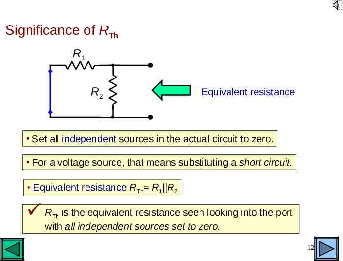
Significance of RTh R1 Vo R2 Equivalent resistance Set all independent sources in the actual circuit to zero. For a voltage source, that means substituting a short circuit. Equivalent resistance RTh R1 R2 R is the equivalent resistance seen looking into the port with all independent sources set to zero. Th 12
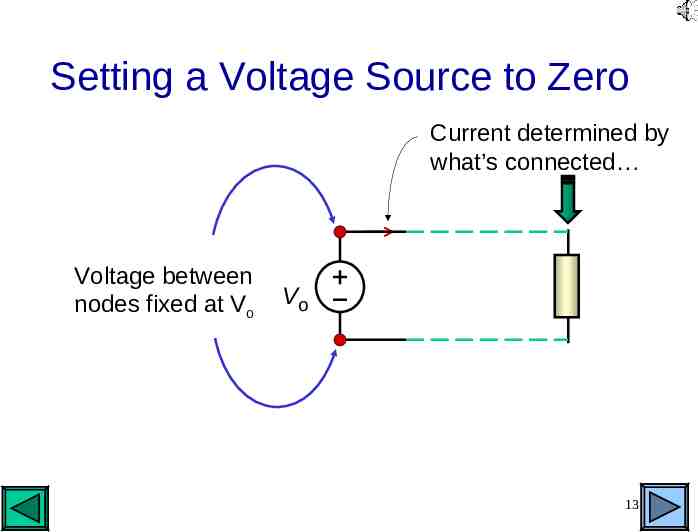
Setting a Voltage Source to Zero Current determined by what’s connected Voltage between nodes fixed at Vo Vo 13
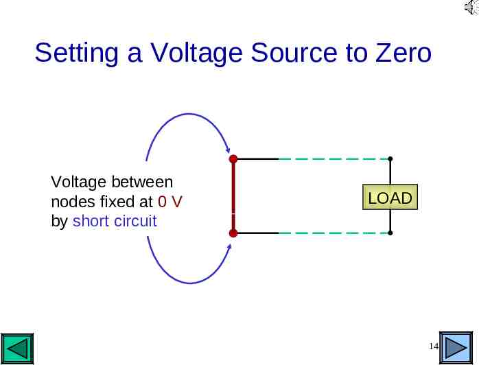
Setting a Voltage Source to Zero Voltage between nodes fixed at 0 V by short circuit LOAD 14
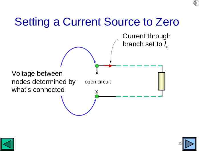
Setting a Current Source to Zero Current through branch set to Io x Voltage between nodes determined by Ioopen circuit what’s connected x 15
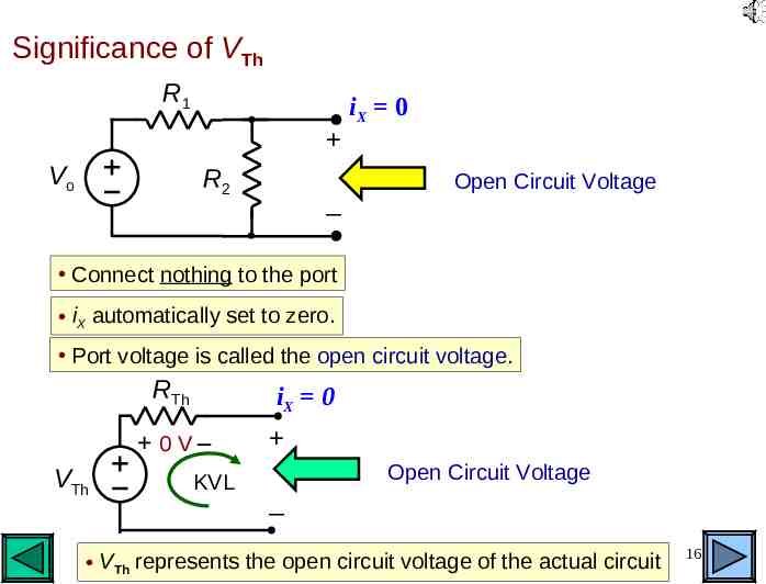
Significance of VTh R1 Vo R2 iX 0 Open Circuit Voltage Connect nothing to the port iX automatically set to zero. Port voltage is called the open circuit voltage. RTh iX 0 0V– VTh KVL Open Circuit Voltage VTh represents the open circuit voltage of the actual circuit 16
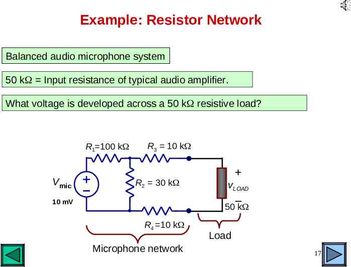
Example: Resistor Network Balanced audio microphone system 50 k Input resistance of typical audio amplifier. What voltage is developed across a 50 k resistive load? R1 100 k Vmic R3 10 k R2 30 k vLOAD – 10 mV 50 k R4 10 k Microphone network Load 17
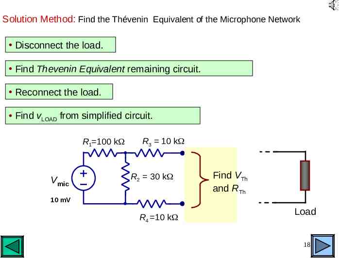
Solution Method: Find the Thévenin Equivalent of the Microphone Network Disconnect the load. Find Thevenin Equivalent remaining circuit. Reconnect the load. Find vLOAD from simplified circuit. R1 100 k Vmic R3 10 k R2 30 k Find VTh and RTh 10 mV R4 10 k Load Load 18
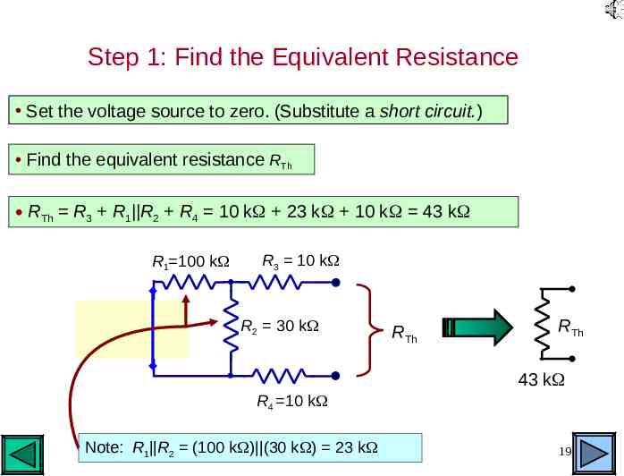
Step 1: Find the Equivalent Resistance Set the voltage source to zero. (Substitute a short circuit.) Find the equivalent resistance RTh RTh R3 R1 R2 R4 10 k 23 k 10 k 43 k R1 100 k Vmic R3 10 k R2 30 k RTh RTh 43 k R4 10 k Note: R1 R2 (100 k ) (30 k ) 23 k 19
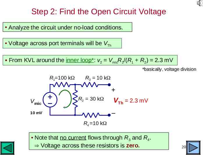
Step 2: Find the Open Circuit Voltage Analyze the circuit under no-load conditions. Voltage across port terminals will be VTh From KVL around the inner loop*: v2 VmicR2/(R1 R2) 2.3 mV *basically, voltage division R1 100 k Vmic R3 10 k R2 30 k VTh 2.3 mV – 10 mV R4 10 k Note that no current flows through R3 and R4. Voltage across these resistors is zero. 20
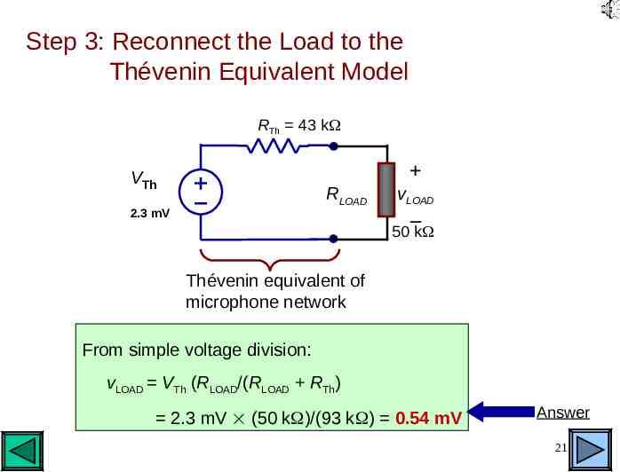
Step 3: Reconnect the Load to the Thévenin Equivalent Model RTh 43 k VTh RLOAD 2.3 mV vLOAD – 50 k Thévenin equivalent of microphone network From simple voltage division: vLOAD VTh (RLOAD/(RLOAD RTh) 2.3 mV (50 k )/(93 k ) 0.54 mV Answer 21
More Examples: The Norton Equivalent Circuit 22
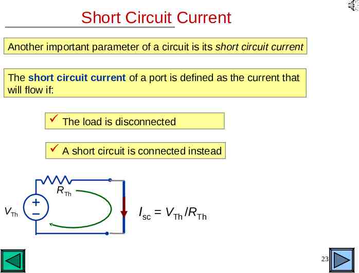
Short Circuit Current Another important parameter of a circuit is its short circuit current The short circuit current of a port is defined as the current that will flow if: The load is disconnected A short circuit is connected instead RTh VTh Isc VTh /RTh 23
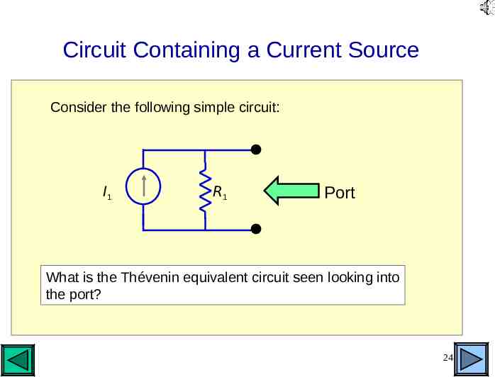
Circuit Containing a Current Source Consider the following simple circuit: I1 R1 Port What is the Thévenin equivalent circuit seen looking into the port? 24
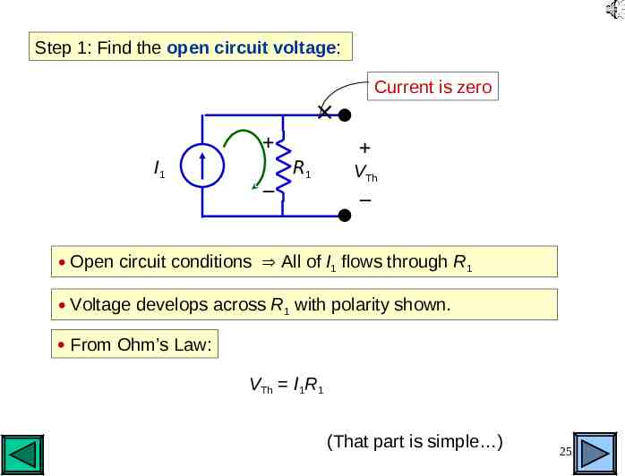
Step 1: Find the open circuit voltage: Current is zero I1 – R1 VTh – Open circuit conditions All of I1 flows through R1 Voltage develops across R1 with polarity shown. From Ohm’s Law: VTh I1R1 (That part is simple ) 25
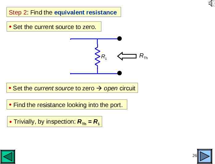
Step 2: Find the equivalent resistance Set the current source to zero. I1 R1 RTh Set the current source to zero open circuit Find the resistance looking into the port. Trivially, by inspection: RTh R1 26
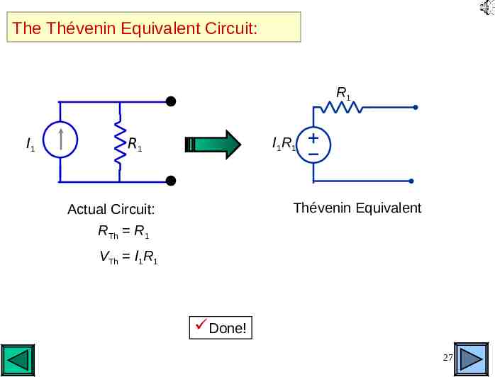
The Thévenin Equivalent Circuit: R1 I1 I1 R 1 R1 Thévenin Equivalent Actual Circuit: RTh R1 VTh I1R1 Done! 27
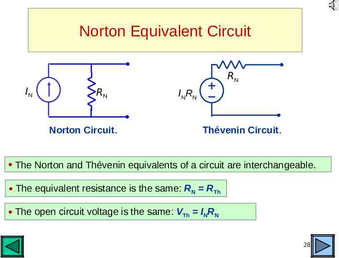
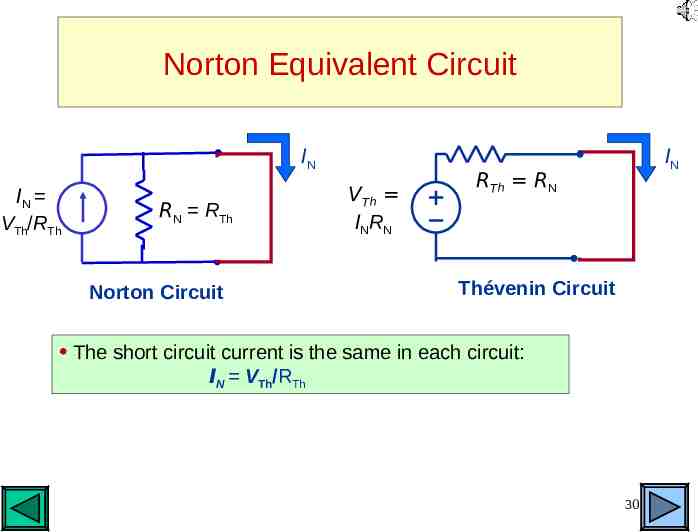
Norton Equivalent Circuit RN IN RN Norton Circuit. IN R N Thévenin Circuit. The Norton and Thévenin equivalents of a circuit are interchangeable. The equivalent resistance is the same: RN RTh The open circuit voltage is the same: VTh INRN 28
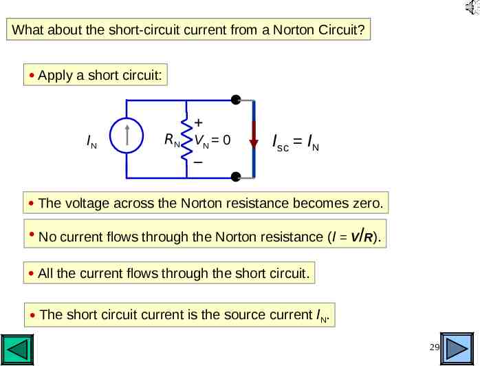
What about the short-circuit current from a Norton Circuit? Apply a short circuit: IN RN VN 0 – Isc IN The voltage across the Norton resistance becomes zero. No current flows through the Norton resistance (I V/R). All the current flows through the short circuit. The short circuit current is the source current IN. 29
Norton Equivalent Circuit IN IN VTh/RTh RN RTh Norton Circuit VTh INRN IN RTh RN Thévenin Circuit The short circuit current is the same in each circuit: IN VTh/RTh 30
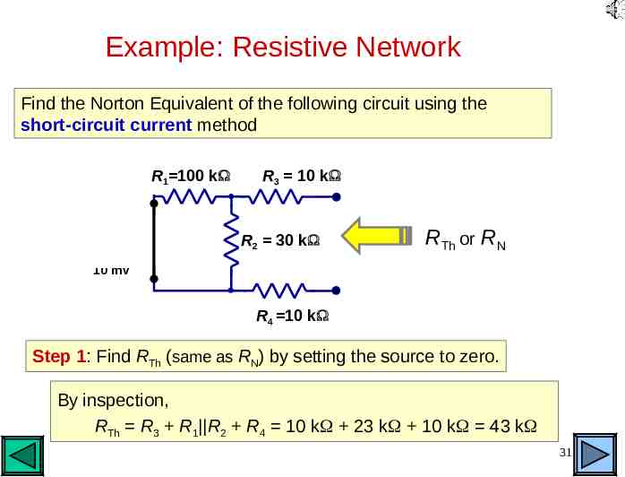
Example: Resistive Network Find the Norton Equivalent of the following circuit using the short-circuit current method R1 100 k Vmic R3 10 k R2 30 k RTh or RN 10 mV R4 10 k Step 1: Find RTh (same as RN) by setting the source to zero. By inspection, RTh R3 R1 R2 R4 10 k 23 k 10 k 43 k 31
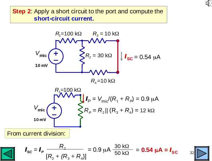
Step 2: Apply a short circuit to the port and compute the short-circuit current. R3 10 k R1 100 k Vmic R2 30 k ISC 0.54 A 10 mV R4 10 k R1 100 k IP Vmic/(R1 RP) 0.9 A Vmic RP R2 (R3 R4) 12 k 10 mV From current division: ISC IP R2 [R2 (R3 R4)] 0.9 A 30 k 50 k 0.54 A ISC 32
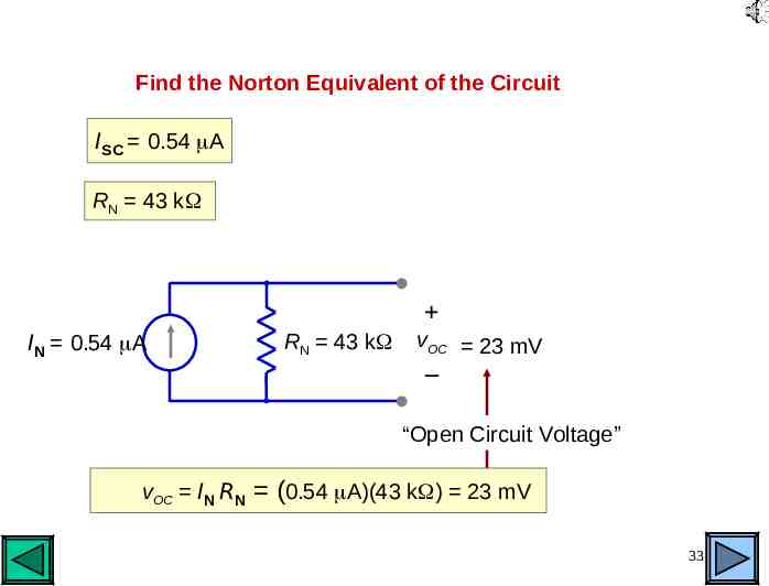
Find the Norton Equivalent of the Circuit ISC 0.54 A RN 43 k IN 0.54 A RN 43 k vOC 23 mV – “Open Circuit Voltage” vOC IN RN (0.54 A)(43 k ) 23 mV 33
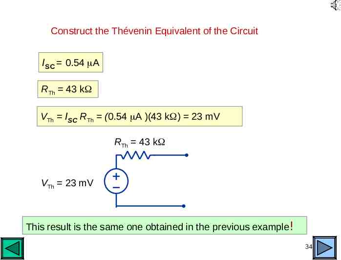
Construct the Thévenin Equivalent of the Circuit ISC 0.54 A RTh 43 k VTh ISC RTh (0.54 A )(43 k ) 23 mV RTh 43 k VTh 23 mV This result is the same one obtained in the previous example! 34
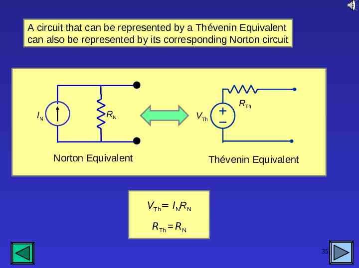
A circuit that can be represented by a Thévenin Equivalent can also be represented by its corresponding Norton circuit IN RTh RN VTh Norton Equivalent Thévenin Equivalent VTh INRN RTh RN 35
End of This Module Do the Homework Exercises 36