UABeam: UAV-Based Beamforming System Analysis with In-Field


26 Slides2.79 MB
UABeam: UAV-Based Beamforming System Analysis with In-Field Air-to-Ground Channels Yan Shi, Rita Enami, John Wensowitch, and Joseph Camp Department of Electrical Engineering Southern Methodist University IEEE SECON, Hong Kong, 2018 1
Outline Introduction Existing Works System Design Experiments and Results Conclusion IEEE SECON, Hong Kong, 2018 2
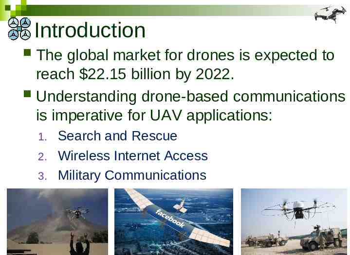
Introduction The global market for drones is expected to reach 22.15 billion by 2022. Understanding drone-based communications is imperative for UAV applications: 1. 2. 3. Search and Rescue Wireless Internet Access Military Communications 3
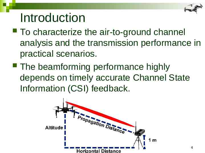
Introduction To characterize the air-to-ground channel analysis and the transmission performance in practical scenarios. The beamforming performance highly depends on timely accurate Channel State Information (CSI) feedback. 4
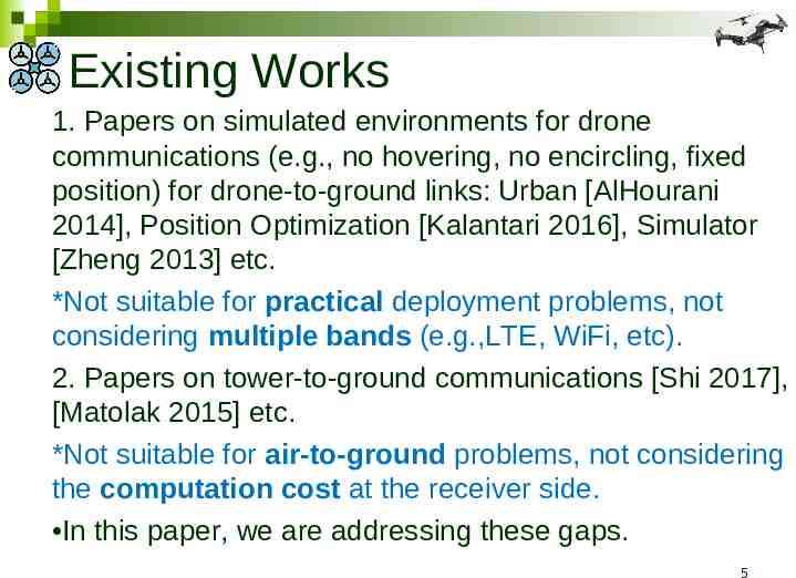
Existing Works 1. Papers on simulated environments for drone communications (e.g., no hovering, no encircling, fixed position) for drone-to-ground links: Urban [AlHourani 2014], Position Optimization [Kalantari 2016], Simulator [Zheng 2013] etc. *Not suitable for practical deployment problems, not considering multiple bands (e.g.,LTE, WiFi, etc). 2. Papers on tower-to-ground communications [Shi 2017], [Matolak 2015] etc. *Not suitable for air-to-ground problems, not considering the computation cost at the receiver side. In this paper, we are addressing these gaps. 5
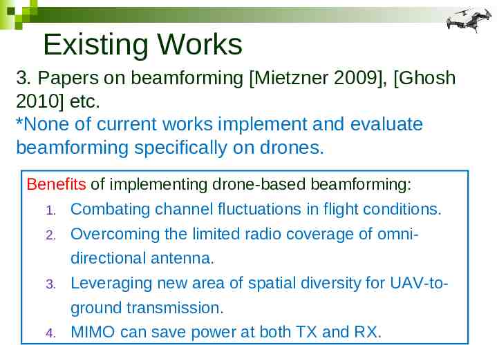
Existing Works 3. Papers on beamforming [Mietzner 2009], [Ghosh 2010] etc. *None of current works implement and evaluate beamforming specifically on drones. Benefits of implementing drone-based beamforming: 1. Combating channel fluctuations in flight conditions. 2. Overcoming the limited radio coverage of omnidirectional antenna. 3. Leveraging new area of spatial diversity for UAV-toground transmission. 4. MIMO can save power at both TX and RX.
Existing Challenges Three major uncertainties to evaluate when it comes to deploying beamforming systems on a UAV: 1. 2. 3. Will the overhead induced by feeding back the CSI consume any beamforming gain in highly-mobile scenarios common to drones? Can channel reciprocity be assumed or exploited in some capacity to minimize feedback overhead How frequently does CSI have to be fed back to the transmitter to support various drone topologies?
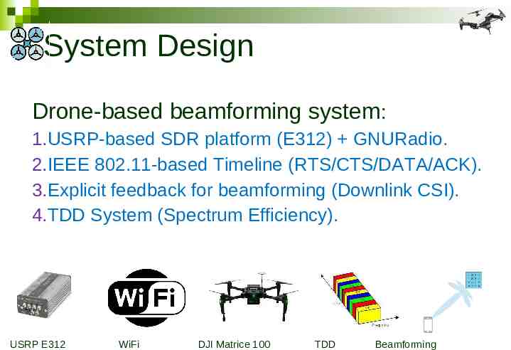
System Design Drone-based beamforming system: 1.USRP-based SDR platform (E312) GNURadio. 2.IEEE 802.11-based Timeline (RTS/CTS/DATA/ACK). 3.Explicit feedback for beamforming (Downlink CSI). 4.TDD System (Spectrum Efficiency). USRP E312 WiFi DJI Matrice 100 TDD Beamforming
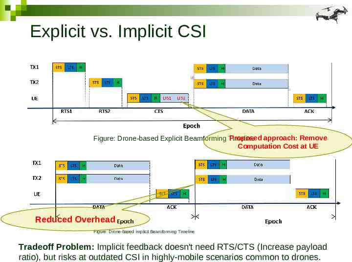
Explicit vs. Implicit CSI Proposed approach: Remove Figure: Drone-based Explicit Beamforming Timeline Computation Cost at UE Reduced Overhead Figure: Drone-based implicit Beamforming Timeline Tradeoff Problem: Implicit feedback doesn't need RTS/CTS (Increase payload ratio), but risks at outdated CSI in highly-mobile scenarios common to drones.
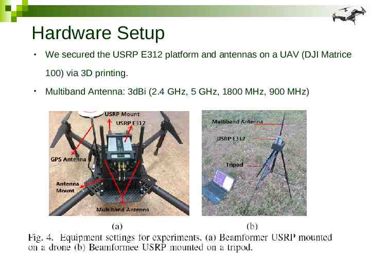
Hardware Setup We secured the USRP E312 platform and antennas on a UAV (DJI Matrice 100) via 3D printing. Multiband Antenna: 3dBi (2.4 GHz, 5 GHz, 1800 MHz, 900 MHz)
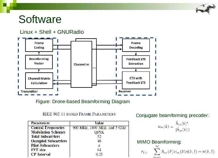
Software Linux Shell GNURadio Figure: Drone-based Beamforming Diagram Conjugate beamforming precoder: MIMO Beamforming:
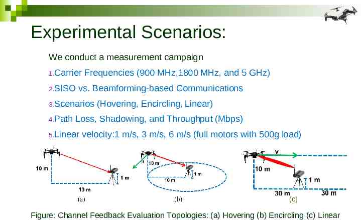
Experimental Scenarios: We conduct a measurement campaign 1.Carrier 2.SISO Frequencies (900 MHz,1800 MHz, and 5 GHz) vs. Beamforming-based Communications 3.Scenarios 4.Path (Hovering, Encircling, Linear) Loss, Shadowing, and Throughput (Mbps) 5.Linear velocity:1 m/s, 3 m/s, 6 m/s (full motors with 500g load) (c) Figure: Channel Feedback Evaluation Topologies: (a) Hovering (b) Encircling (c) Linear
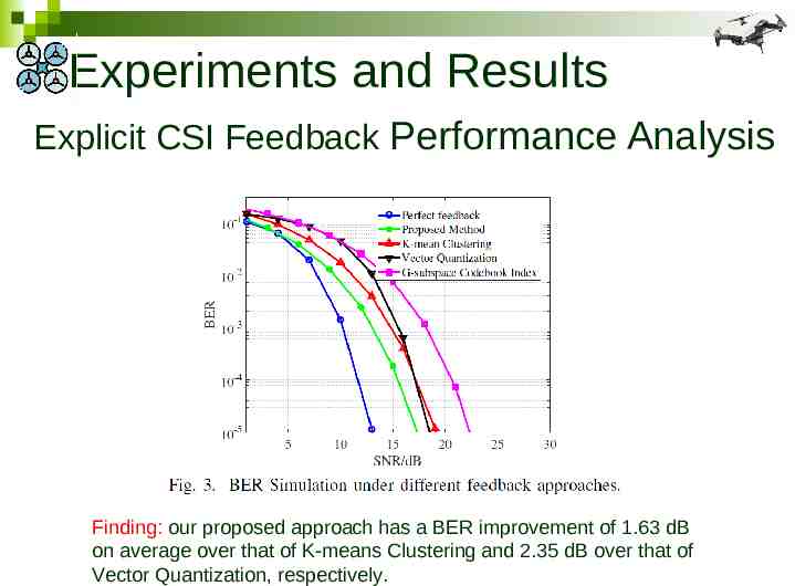
Experiments and Results Explicit CSI Feedback Performance Analysis Finding: our proposed approach has a BER improvement of 1.63 dB on average over that of K-means Clustering and 2.35 dB over that of Vector Quantization, respectively.
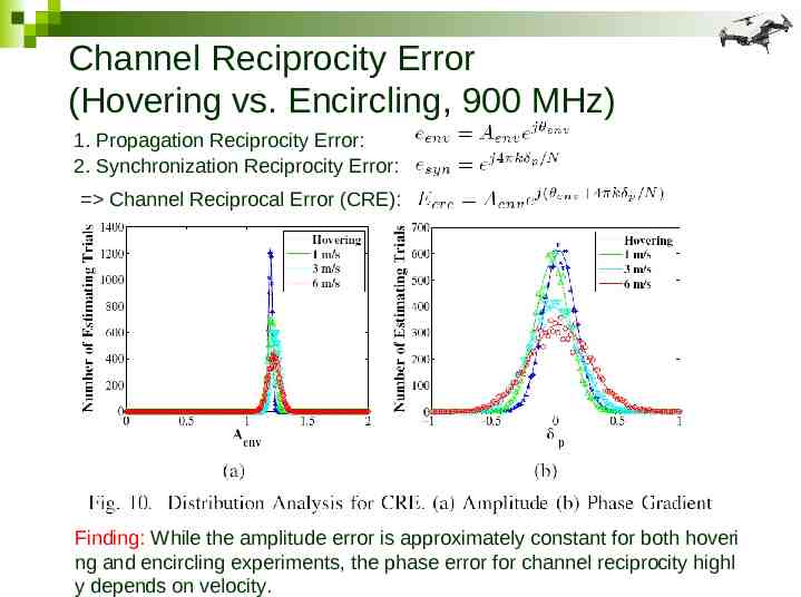
Channel Reciprocity Error (Hovering vs. Encircling, 900 MHz) 1. Propagation Reciprocity Error: 2. Synchronization Reciprocity Error: Channel Reciprocal Error (CRE): Finding: While the amplitude error is approximately constant for both hoveri ng and encircling experiments, the phase error for channel reciprocity highl y depends on velocity.
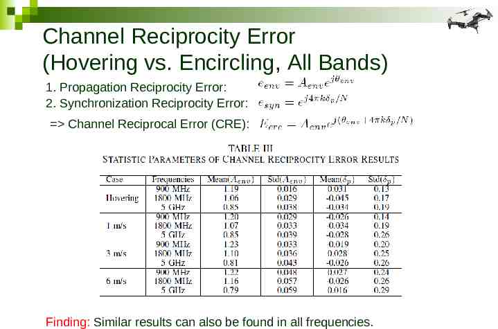
Channel Reciprocity Error (Hovering vs. Encircling, All Bands) 1. Propagation Reciprocity Error: 2. Synchronization Reciprocity Error: Channel Reciprocal Error (CRE): Finding: Similar results can also be found in all frequencies.
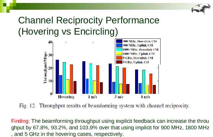
Channel Reciprocity Performance (Hovering vs Encircling) Finding: The beamforming throughput using explicit feedback can increase the throu ghput by 67.8%, 93.2%, and 103.9% over that using implicit for 900 MHz, 1800 MHz , and 5 GHz in the hovering cases, respectively.
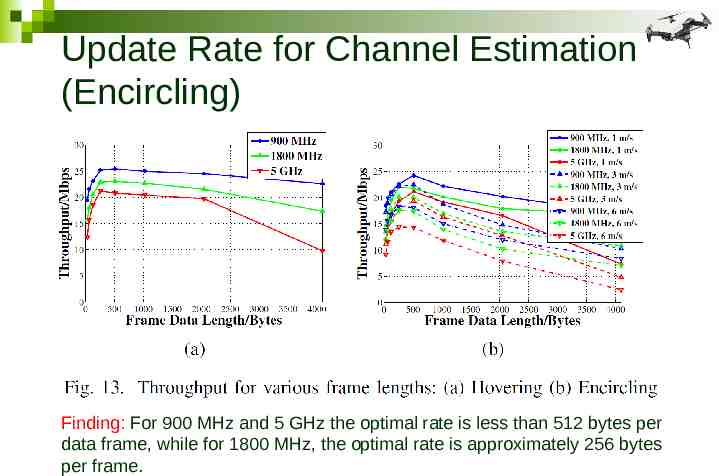
Update Rate for Channel Estimation (Encircling) Finding: For 900 MHz and 5 GHz the optimal rate is less than 512 bytes per data frame, while for 1800 MHz, the optimal rate is approximately 256 bytes per frame.
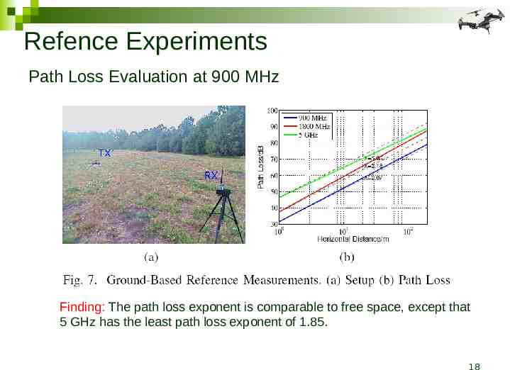
Refence Experiments Path Loss Evaluation at 900 MHz Finding: The path loss exponent is comparable to free space, except that 5 GHz has the least path loss exponent of 1.85. 18
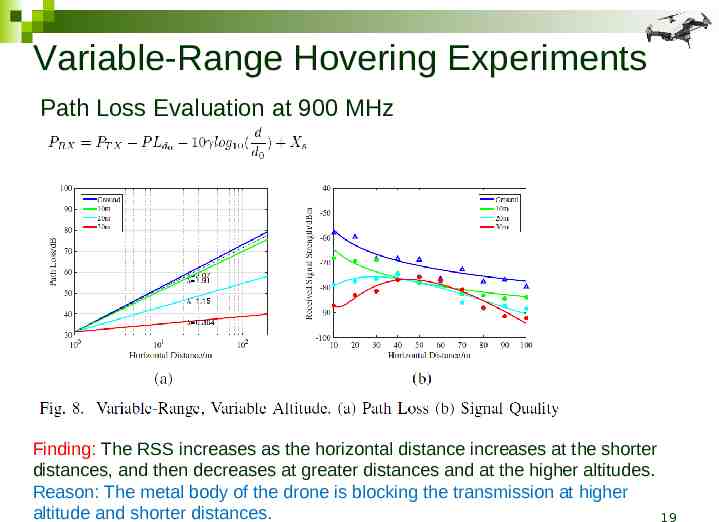
Variable-Range Hovering Experiments Path Loss Evaluation at 900 MHz Finding: The RSS increases as the horizontal distance increases at the shorter distances, and then decreases at greater distances and at the higher altitudes. Reason: The metal body of the drone is blocking the transmission at higher altitude and shorter distances. 19
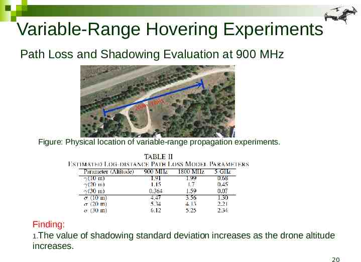
Variable-Range Hovering Experiments Path Loss and Shadowing Evaluation at 900 MHz Figure: Physical location of variable-range propagation experiments. Finding: 1.The value of shadowing standard deviation increases as the drone altitude increases. 20
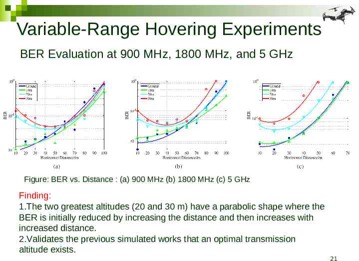
Variable-Range Hovering Experiments BER Evaluation at 900 MHz, 1800 MHz, and 5 GHz Figure: BER vs. Distance : (a) 900 MHz (b) 1800 MHz (c) 5 GHz Finding: 1.The two greatest altitudes (20 and 30 m) have a parabolic shape where the BER is initially reduced by increasing the distance and then increases with increased distance. 2.Validates the previous simulated works that an optimal transmission altitude exists. 21
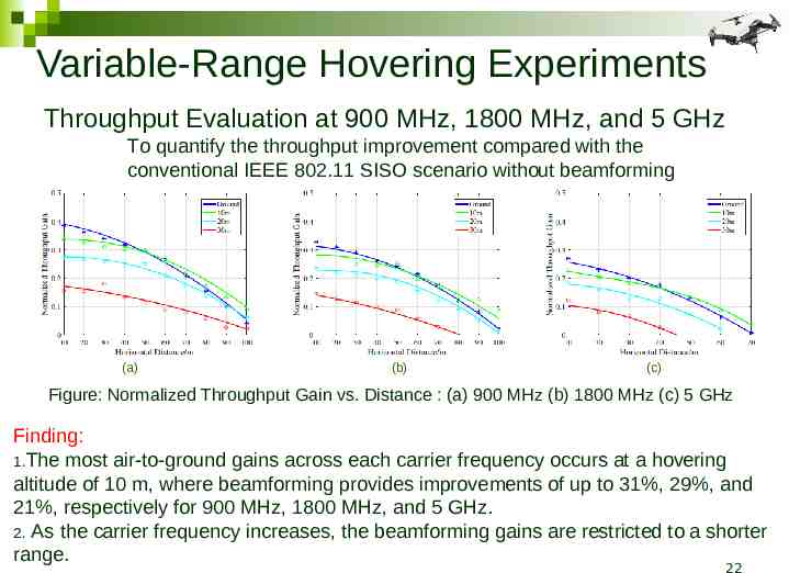
Variable-Range Hovering Experiments Throughput Evaluation at 900 MHz, 1800 MHz, and 5 GHz To quantify the throughput improvement compared with the conventional IEEE 802.11 SISO scenario without beamforming (a) (b) (c) Figure: Normalized Throughput Gain vs. Distance : (a) 900 MHz (b) 1800 MHz (c) 5 GHz Finding: 1.The most air-to-ground gains across each carrier frequency occurs at a hovering altitude of 10 m, where beamforming provides improvements of up to 31%, 29%, and 21%, respectively for 900 MHz, 1800 MHz, and 5 GHz. 2. As the carrier frequency increases, the beamforming gains are restricted to a shorter range. 22
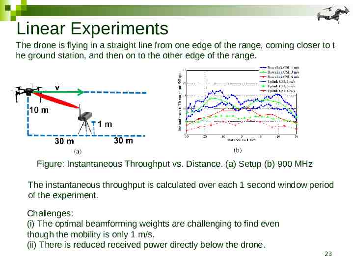
Linear Experiments The drone is flying in a straight line from one edge of the range, coming closer to t he ground station, and then on to the other edge of the range. Figure: Instantaneous Throughput vs. Distance. (a) Setup (b) 900 MHz The instantaneous throughput is calculated over each 1 second window period of the experiment. Challenges: (i) The optimal beamforming weights are challenging to find even though the mobility is only 1 m/s. (ii) There is reduced received power directly below the drone. 23
Conclusion 1. A properly optimized drone-based beamforming system can provide significant throughput improvement using explicit versus implicit feedback. 2. The optimal update rate for channel estimation are similar across frequencies. 3. In channel reciprocity error, the amplitude error remained steady while the phase error highly depends on mobility. 24
Conclusion 4. The value of shadowing standard deviation increases as the drone altitude increases. 5. Experimental validation on the existence of an unique optimal drone altitude for transmissions in a given situation. 25
Thank you! Questions? 26