South Carolina DOT Training Workshop Geophysics Field Testing


28 Slides3.41 MB
South Carolina DOT Training Workshop Geophysics Field Testing Methods, Data Reduction, and Interpretation of Results Robert C. Bachus and Glenn J. Rix June 5 – 26, 2020
Electrical Resistivity
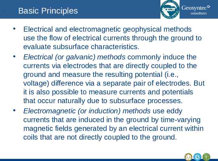
Basic Principles Electrical and electromagnetic geophysical methods use the flow of electrical currents through the ground to evaluate subsurface characteristics. Electrical (or galvanic) methods commonly induce the currents via electrodes that are directly coupled to the ground and measure the resulting potential (i.e., voltage) difference via a separate pair of electrodes. But it is also possible to measure currents and potentials that occur naturally due to subsurface processes. Electromagnetic (or induction) methods use eddy currents that are induced in the ground by time-varying magnetic fields generated by an electrical current within coils that are not directly coupled to the ground.
Strengths Because surface geophysical methods are noninvasive, they provide the ability to cover a large area in a time- and cost-effective manner to gain an understanding of the overall subsurface conditions. This characteristic enables optimizing the locations of borings and soundings during subsequent phases of a subsurface exploration program or interpolating between existing borings and soundings. Geophysical methods are robust in the sense that they are based on fundamental physical principles with relatively little reliance on empiricism. In many cases, the methods used for geotechnical applications leverage the extensive experience gained with similar methods developed for resource (e.g., oil, gas) exploration. Surface geophysical methods are also useful for sites where borings and soundings are difficult or impractical, such as gravel deposits or contaminated soils. The equipment used for many geophysical tests is highly portable, which may allow testing at sites that are not easily accessible (e.g., a heavily wooded area) using conventional drilling equipment.
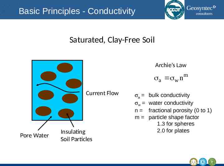
Basic Principles - Conductivity Saturated, Clay-Free Soil Archie’s Law a w n m Current Flow Pore Water Insulating Soil Particles sa sw n m bulk conductivity water conductivity fractional porosity (0 to 1) particle shape factor 1.3 for spheres 2.0 for plates
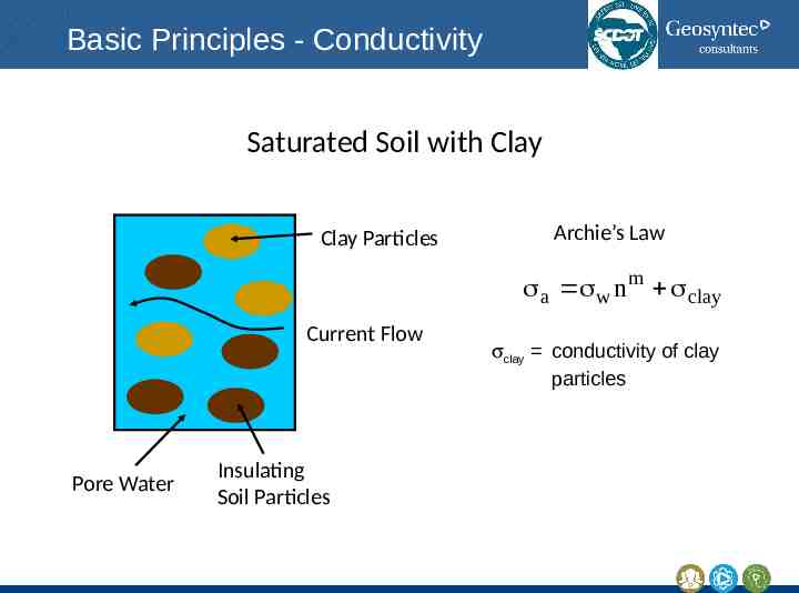
Basic Principles - Conductivity Saturated Soil with Clay Clay Particles Archie’s Law a w n m clay Current Flow Pore Water Insulating Soil Particles sclay conductivity of clay particles
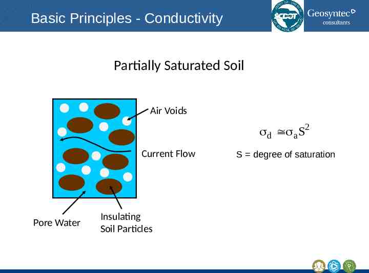
Basic Principles - Conductivity Partially Saturated Soil Air Voids d a S2 Current Flow Pore Water Insulating Soil Particles S degree of saturation
Basic Principles - Conductivity Ground conductivity varies with: Soil structure (coarser structure and/or smaller porosity produces lower conductivity) Clay content (increasing clay fraction produces higher conductivity) Soil moisture content (increasing moisture content/saturation produces higher conductivity) Chemistry of the pore fluid
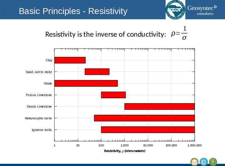
Basic Principles - Resistivity 1 Resistivity is the inverse of conductivity: 𝜌 𝜎 Clay Sand, wet to moist Shale Porous Limestone Dense Limestone Metamorphic rocks Igneous rocks 1 10 100 1,000 10,000 Resistivity, ρ (ohm-meters) 100,000 1,000,000
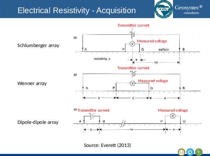
Electrical Resistivity - Acquisition Transmitter current Measured voltage Schlumberger array Transmitter current Measured voltage Wenner array Transmitter current Dipole-dipole array Source: Everett (2013) Measured voltage
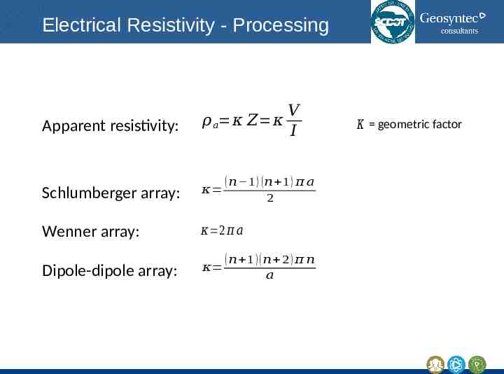
Electrical Resistivity - Processing Apparent resistivity: 𝜌 𝑎 𝜅 𝑍 𝜅 𝑉 𝐼 ( 𝑛 1 ) ( 𝑛 1 ) 𝜋 𝑎 2 Schlumberger array: 𝜅 Wenner array: 𝜅 2 𝜋 𝑎 Dipole-dipole array: 𝜅 ( 𝑛 1 )( 𝑛 2 ) 𝜋 𝑛 𝑎 𝜅 geometric factor
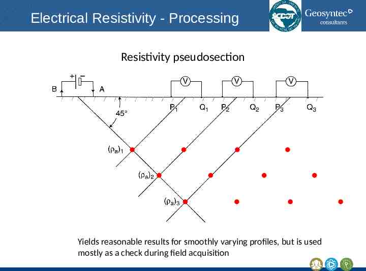
Electrical Resistivity - Processing Resistivity pseudosection Yields reasonable results for smoothly varying profiles, but is used mostly as a check during field acquisition
Electrical Resistivity Tomography (ERT) Electrical resistivity tomography or electrical resistivity imaging are based on using numerous combinations of four-electrode arrays from a large, multielectrode cable. For each four-electrode array, the calculated and measured pseudosections are compared, and the resistivities within a 2D or 3D model are adjusted until satisfactory agreement is obtained (i.e., an inversion problem).
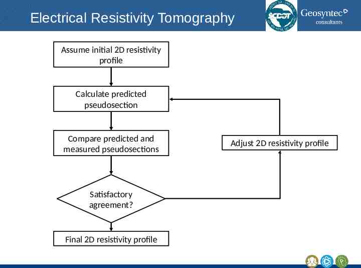
Electrical Resistivity Tomography Assume initial 2D resistivity profile Calculate predicted pseudosection Compare predicted and measured pseudosections Satisfactory agreement? Final 2D resistivity profile Adjust 2D resistivity profile
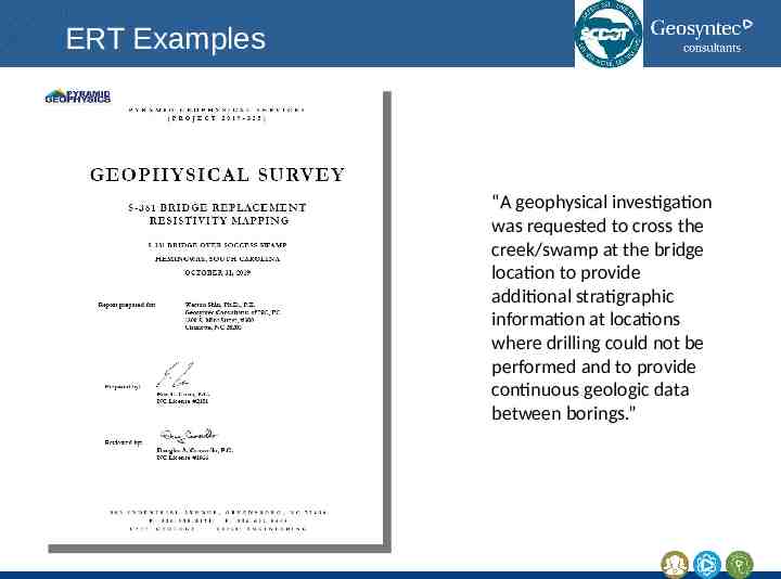
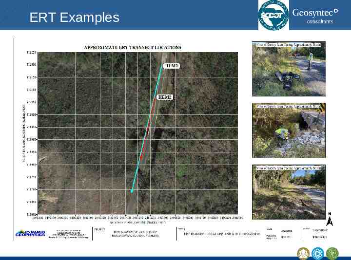
ERT Examples “A geophysical investigation was requested to cross the creek/swamp at the bridge location to provide additional stratigraphic information at locations where drilling could not be performed and to provide continuous geologic data between borings.”
ERT Examples
ERT Examples
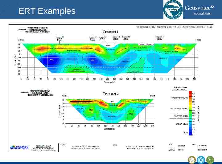
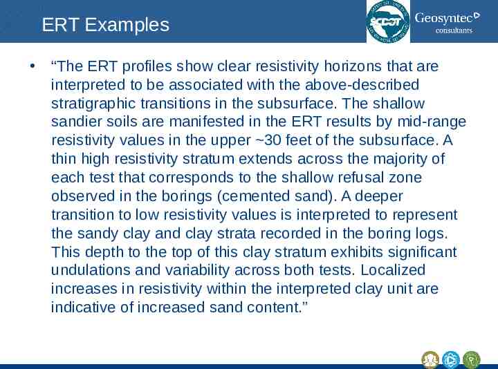
ERT Examples “The ERT profiles show clear resistivity horizons that are interpreted to be associated with the above-described stratigraphic transitions in the subsurface. The shallow sandier soils are manifested in the ERT results by mid-range resistivity values in the upper 30 feet of the subsurface. A thin high resistivity stratum extends across the majority of each test that corresponds to the shallow refusal zone observed in the borings (cemented sand). A deeper transition to low resistivity values is interpreted to represent the sandy clay and clay strata recorded in the boring logs. This depth to the top of this clay stratum exhibits significant undulations and variability across both tests. Localized increases in resistivity within the interpreted clay unit are indicative of increased sand content.”
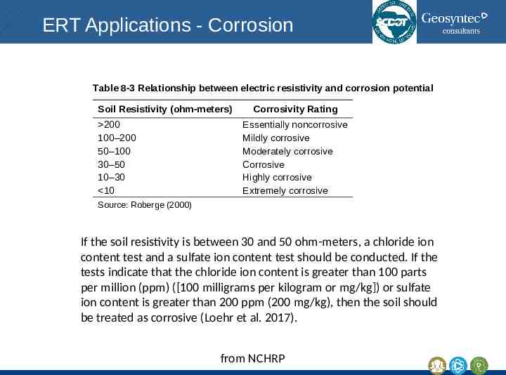
ERT Applications - Corrosion Table 8-3 Relationship between electric resistivity and corrosion potential Soil Resistivity (ohm-meters) 200 100–200 50–100 30–50 10–30 10 Corrosivity Rating Essentially noncorrosive Mildly corrosive Moderately corrosive Corrosive Highly corrosive Extremely corrosive Source: Roberge (2000) If the soil resistivity is between 30 and 50 ohm-meters, a chloride ion content test and a sulfate ion content test should be conducted. If the tests indicate that the chloride ion content is greater than 100 parts per million (ppm) ([100 milligrams per kilogram or mg/kg]) or sulfate ion content is greater than 200 ppm (200 mg/kg), then the soil should be treated as corrosive (Loehr et al. 2017). from NCHRP
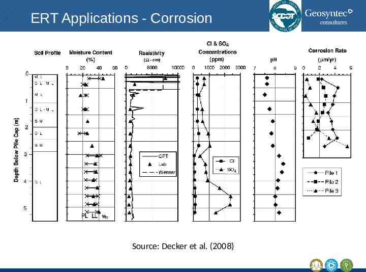
ERT Applications - Corrosion Source: Decker et al. (2008)
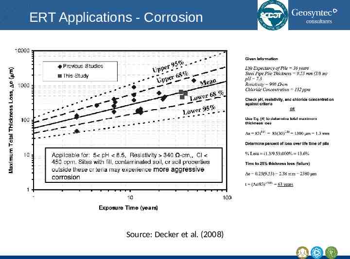
ERT Applications - Corrosion Source: Decker et al. (2008)
Closing Thoughts
Basic Principles Geophysical investigations are used to estimate the physical properties of the subsurface by measuring, analyzing, and interpreting seismic, electrical, electromagnetic, gravitational, and magnetic fields measured at the ground surface or within boreholes.
Strengths Because surface geophysical methods are noninvasive, they provide the ability to cover a large area in a time- and cost-effective manner to gain an understanding of the overall subsurface conditions. This characteristic enables optimizing the locations of borings and soundings during subsequent phases of a subsurface exploration program or interpolating between existing borings and soundings. Geophysical methods are robust in the sense that they are based on fundamental physical principles with relatively little reliance on empiricism. In many cases, the methods used for geotechnical applications leverage the extensive experience gained with similar methods developed for resource (e.g., oil, gas) exploration. Surface geophysical methods are also useful for sites where borings and soundings are difficult or impractical, such as gravel deposits or contaminated soils. The equipment used for many geophysical tests is highly portable, which may allow testing at sites that are not easily accessible (e.g., a heavily wooded area) using conventional drilling equipment.
Limitations Geophysical methods are more likely to yield good results when (i) there is a large contrast in seismic, electrical, electromagnetic, gravitational, or magnetic properties between lithologic units or between an anomaly and the surrounding soils and rocks, and (ii) the subsurface features of interest are of sufficient size relative to their depth that they are within the limits of detection for a particular geophysical method. The interpreted subsurface conditions may not be unique for many geophysical methods; there may be multiple, physically plausible interpretations for the stratigraphy or location and size of anomalies that all yield the same measured geophysical response. For example, a structural low in bedrock topography; a small, air-filled void in the bedrock; or a larger, water-filled void in the bedrock may all produce the same magnitude of gravity anomaly. Sites that have a stiff, surficial layer overlying a weaker layer or an electrically resistive layer over a conductive layer pose a challenge for many surface geophysical tests. For example, many seismic methods do not work well on concrete pavements because of the large stiffness of the pavement compared to the base and subgrade materials.
Implementation Because geophysical methods are less familiar to many geotechnical engineers than conventional site investigation methods (e.g., SPT, CPT), it is essential that geophysical investigations be conducted by personnel who are trained and experienced in near-surface geophysics. The results of geophysical investigations should always be complemented by direct observation of subsurface conditions by means of borings, soundings, test pits, trenches, outcrops, and other geological information. This ground truth information will help ensure that interpreted subsurface conditions derived from geophysical methods are as accurate as possible. The combined use of a geophysical investigation with direct observation is a robust approach to developing an accurate ground model for a project.
Implementation Planning the investigation – Developing a geophysical testing plan – Selecting the number and locations for in situ tests, drilling, and sampling – Determining the minimum depth of investigation at each location – Determining the required types of samples and the sampling frequency – Developing an in situ and laboratory testing plan – Developing a plan for evaluating groundwater conditions Executing the investigation Interpreting the results of the investigation Reporting and presenting results of the investigation
Planning a Geophysical Investigation What are the physical properties of interest? Which methods respond to the physical properties of interest? Which methods can provide the required levels of detection and resolution for the subsurface features of interest? Which methods can perform well given conditions at the project site? Which methods provide complementary information to help improve interpretations based on the observed data? What direct observations (e.g., borings or soundings) should be performed to constrain the interpretation of geophysical data? Which methods are most cost effective, and is the overall geophysical investigation cost effective?