ECEN 460, Spring 2024 Power System Operation and Control Class


41 Slides7.17 MB
ECEN 460, Spring 2024 Power System Operation and Control Class 7: Transmission Lines, Part 1 Prof. Adam Birchfield Dept. of Electrical and Computer Engineering Texas A&M University [email protected]
2 Homework 4 Due Next Week No homework on generators. Make sure you understand the lecture notes and labs 3 and 4 (starting next week). Homework 3 on transformers: book problems 3.4, 3.23, due Feb. 8th. Homework 4 on transmission lines: book regular problems 4.10, 4.11, 4.20, and 4.41, 5.14 (a,b), 5.38, and 5.41 (a,b), due Feb. 15th.
3 Transmission Lines In this class, we give an overview of line and transformer modeling – – More detailed coverage of some models is in ECEN 459 Our focus is on how to use the models to study power systems Primary methods for long distance electric power transfer – – – Overhead ac Underground ac HVDC – overhead or underground
4 345 kV Transmission Growth at a Glance
5 345 kV Transmission Growth at a Glance
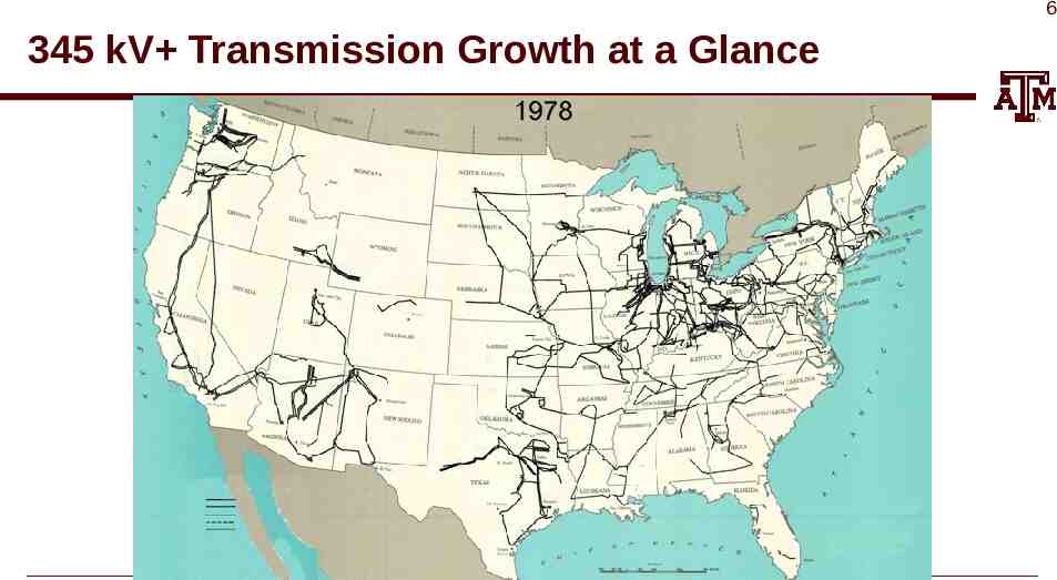
6 345 kV Transmission Growth at a Glance
7 345 kV Transmission Growth at a Glance
8 345 kV Transmission Growth at a Glance
9 HVDC Lines in North America http://www.grainbeltexpresscleanline.com/site/page/ history of hvdc transmission
10 Line Conductors Typical transmission lines use multi-strand conductors ACSR (aluminum conductor steel reinforced) conductors are most common. A typical Al. to St. ratio is about 4 to 1. AAC (all aluminum conductors) are lighter but have less strength; used in urban areas with shorter spans Copper is heavier, but has better conductance; used in cables where weight is not an issue
11 Line Conductors, cont’d Total conductor area is given in circular mils. One circular mil is the area of a circle with a diameter of 0.001 0.00052 square inches Example: what is the the area of a solid, 1” diameter circular wire? Answer: 1000 kcmil (kilo circular mils) Because conductors are stranded, the equivalent radius must be provided by the manufacturer. In tables this value is known as the GMR and is usually expressed in feet.
12 Transmission Line Parameters We'll discuss how to calculate transmission line parameters, which will then form part of the input to our power system model, such as in PowerWorld: – – – – Resistance Inductance Capacitance Ampacity
13 Line Resistance Line resistance per unit length is given by where is the resistivity Resistivity of Copper Resistivity of Aluminum Example: What is the resistance in / mile of a 1” diameter solid aluminum wire (at dc)?
14 Line Resistance, cont’d Because ac current tends to flow towards the surface of a conductor, the resistance of a line at 60 Hz is slightly higher than at dc. Resistivity and hence line resistance increase linearly as conductor temperature increases (changes is about 0.4% per degree C) – In some locations conductor temperatures can vary by up to 100 C! Because ACSR conductors are stranded, actual resistance, inductance and capacitance needs to be determined from tables.
15 Variation in Line Resistance Example Time is in minutes. Input was 30 second ICCP data. Conductor resistance increased by about 50%, indicating a 50/0.4 125 degree C rise in temperature.
16 High Voltage Transmission Line Worker Source: www.youtube.com/watch?v LIjC7DjoVe8
17 Texas Grid, 1943
18 Magnetics Review Ampere’s circuital law: F mmf magnetomotive force (amp-turns) H magnetic field intensity (amp-turns/meter) dl Vector differential path length (meters) Line integral about closed path C Ienc Algebraic sum of current linked by C Ampere’s law is most useful in cases of symmetry, such as with an infinitely long line Line integrals are a generalization of traditional integration Integrate along X-axis Integrate along a general path, which may be closed.
19 Magnetic Flux Density Magnetic fields are usually measured in terms of flux density 𝐁 flux density (Tesla [T] or Gaus [G])
20 Magnetic Flux Total flux passing through a surface A is vector with direction normal to surface If flux density B is uniform and perpendicular to an area A then
21 Magnetic Fields from Single Wire Assume we have an infinitely long wire with current of 1000A. How much magnetic flux passes through a 1 meter square, located between 4 and 5 meters from the wire? Direction of H is given by the “Right-hand” Rule Easiest way to solve the problem is to take advantage of symmetry. For an integration path we’ll choose a circle with a radius of x.
22 Two Conductor Line Inductance Key problem with the previous derivation is we assumed no return path for the current. Now consider the case of two wires, each carrying the same current I, but in opposite directions; assume the wires are separated by distance R. R Creates counterclockwise field Creates a clockwise field To determine the inductance of each conductor we integrate as before. However now we get some field cancellation
23 Two Conductor Case, cont’d R R Rp Direction of integration Left Current Right Current For distance Rp, greater than 2R, from left line Key Point: As we integrate for the left line, at distance 2R from the left line the net flux linked due to the Right line is zero! Use superposition to get total flux linkage.
24 Two Conductor Inductance Simplifying (with equal and op osite cur ents)
25 Many-Conductor Case Now assume we now have k conductors, each with current ik, arranged in some specified geometry. We’d like to find flux linkages of each conductor. Each conductor’s flux linkage, lk, depends upon its own current and the current in all the other conductors. To derive l1 we’ll be integrating from conductor 1 (at origin) to the right along the x-axis.
26 Many-Conductor Case, cont’d which is true in a balanced three phase system, then the second term is zero and System has self and mutual inductance. However, the mutual inductance can be canceled for balanced 3ϕ systems with symmetry.
27 Symmetric Line Spacing – 69 kV
28 Line Inductance Example Calculate the reactance for a balanced 3, 60Hz transmission line with a conductor geometry of an equilateral triangle with D 5m, r 1.24cm (Rook conductor) and a length of 5 miles. Since system is assumed balanced 𝜇0 𝜆𝑎 ¿ 2 𝜋
29 Line Inductance Example, cont’d Substituting
30 Transmission Tower Configurations The problem with the line analysis we’ve done so far is we have assumed a symmetrical tower configuration. Such a tower figuration is seldom practical. Therefore, in general Dab Dac Dbc Unless something was done this would result in unbalanced phases Typical transmission tower configurations
31 Transposition To keep system balanced, over the length of a transmission line the conductors are rotated so each phase occupies each position on tower for an equal distance. This is known as transposition. In practice, not all lines are transposed, but it is a very common assumption for simplicity of calculation Aerial or side view of conductor positions over the length of the transmission line.
32 Inductance of Transposed Line Define the geometric mean distance (GMD)
33 Conductor Bundling To increase the capacity of high voltage transmission lines it is very common to use a number of conductors per phase. This is known as conductor bundling. Typical values are two conductors for 345 kV lines, three for 500 kV and four for 765 kV.
34 Bundled Conductor Pictures The AEP Wyoming-Jackson Ferry 765 kV line uses 6-bundle conductors. Conductors in a bundle are at the same voltage! Photo Source: BPA and American Electric Power
35 Inductance of Lines with Bundled Conductors The per phase inductance is 𝜇0 𝐷 L a ln 2𝜋 𝑅𝑏 The detailed derivation is given in ECEN 459 ( ) When calculating the per phase resistance of bundled lines, the total resistance is R per conductor divided by b, where b is the number of conductors in the bundle
36 Bundle Inductance Example Consider the previous example of the three phases symmetrically spaced 5 meters apart using wire with a radius of r 1.24 cm. Except now assume each phase has 4 conductors in a square bundle, spaced 0.25 meters apart. What is the new inductance per meter? 0.25 M 0.25 M 0.25 M
37 Inductance Example Calculate the per phase inductance and reactance of a balanced 3 , 60 Hz, line with horizontal phase spacing of 10m using three conductor bundling with a spacing between conductors in the bundle of 0.3m. Assume the line is uniformly transposed and the conductors have a 1cm radius. Answer: Dm 12.6 m, Rb 0.0889 m Inductance 9.9 x 10⁻⁷ H/m, Reactance 0.6 /Mile
38 Line Capacitance High voltage transmission lines and cables can have significant capacitance For the case of uniformly transposed lines we
39 Line Capacitance Example Calculate the per phase capacitance and susceptance of a balanced 3 , 60 Hz, transmission line with horizontal phase spacing of 10m using three conductor bundling with a spacing between conductors in the bundle of 0.3m. Assume the line is uniformly transposed and the conductors have a a 1cm radius.
40 Line Capacitance Example, cont’d 𝑐 𝑏 𝑅 ¿
41 Conductor Table Example