HVAC Objective To understand key issues in Qualification of

37 Slides1.73 MB
HVAC Objective To understand key issues in Qualification of HVAC systems 1
HVAC Qualification of the HVAC system is one component in the overall approach that covers premises, systems / utilities, equipment, processes, etc. 2
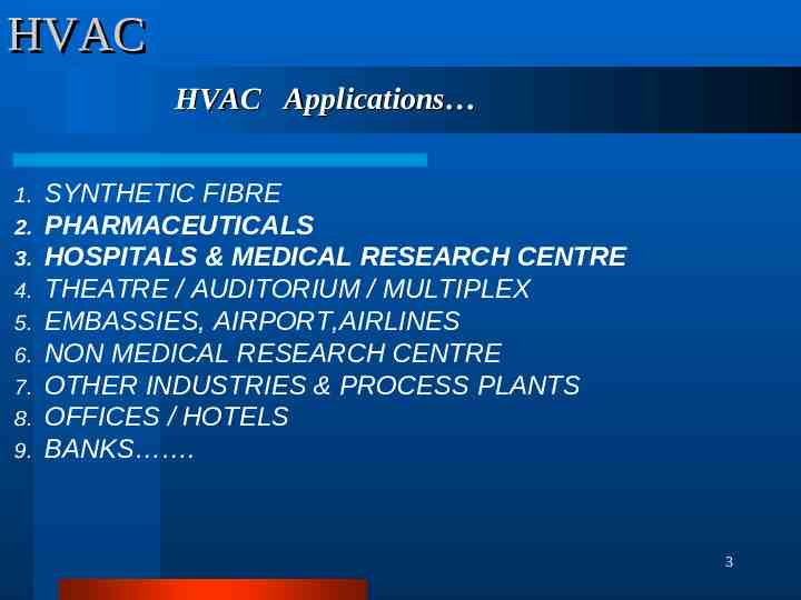
HVAC HVAC Applications 1. 2. 3. 4. 5. 6. 7. 8. 9. SYNTHETIC FIBRE PHARMACEUTICALS HOSPITALS & MEDICAL RESEARCH CENTRE THEATRE / AUDITORIUM / MULTIPLEX EMBASSIES, AIRPORT,AIRLINES NON MEDICAL RESEARCH CENTRE OTHER INDUSTRIES & PROCESS PLANTS OFFICES / HOTELS BANKS . 3
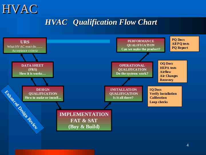
HVAC HVAC Qualification Flow Chart PERFORMANCE QUALIFICATION Can we make the product? URS What HVAC must do Acceptance criteria DATA SHEET (FRS) How it is works OPERATIONAL QUALIFICATION Do the systems work? ed nc ha En DESIGN QUALIFICATION How to make or install. INSTALLATION QUALIFICATION Is it all there? PQ Docs All PQ tests PQ Report OQ Docs HEPA tests Airflow Air Changes Recovery IQ Docs Verify Installation Calibration Loop checks n sig De w vie Re IMPLEMENTATION FAT & SAT (Buy & Build) 4
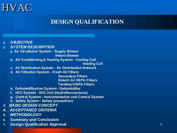
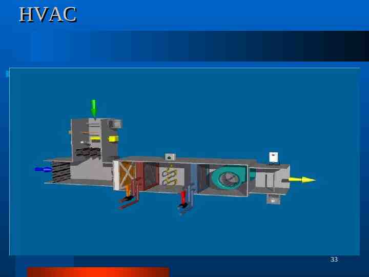
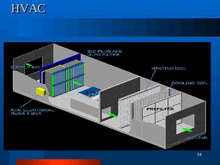
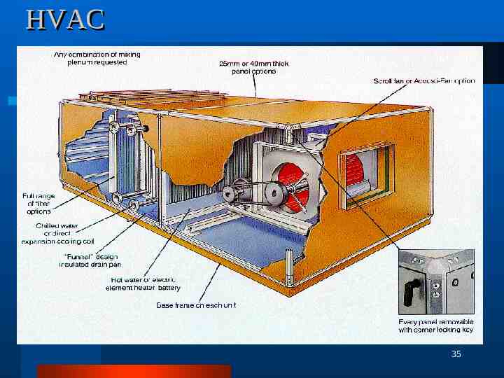
HVAC DESIGN QUALIFICATION 1. 2. OBJECTIVE SYSTEM DESCRIPTION a. Air Circulation System - Supply Blower Return Blower b. Air Conditioning & Heating System - Cooling Coil Heating Coil c. Air Distribution System - Air Distribution Network d. Air Filtration System - Fresh Air Filters Secondary Filters Return Air HEPA Filters Terminal HEPA Filters e. Dehumidification System - Dehumidifier f. HFC System - HFC Unit (Hydroflurocarbons) g. Control System - Instrumentation and Control System h. Safety System - Safety precautions 3. BASIC DESIGN CONCEPT 4. ACCEPTANCE CRITERIA 5. METHODOLOGY 6. Summary and Conclusion 7. Design Qualification Approval 5
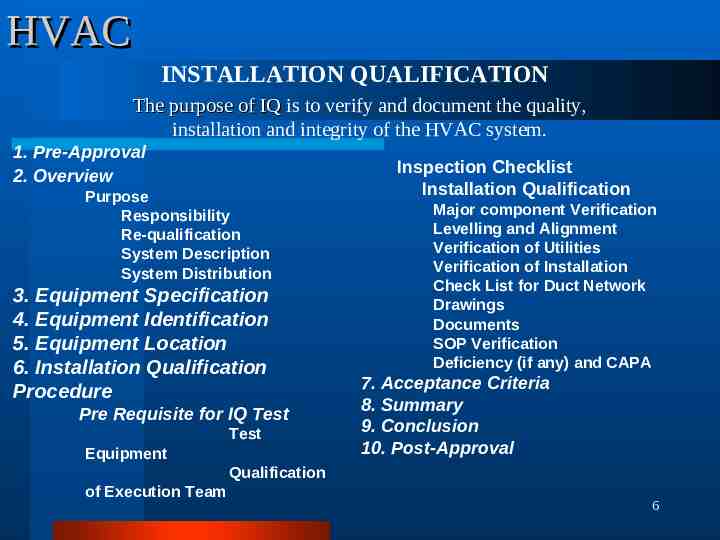
HVAC INSTALLATION QUALIFICATION The purpose of IQ is to verify and document the quality, installation and integrity of the HVAC system. 1. Pre-Approval 2. Overview Purpose Responsibility Re-qualification System Description System Distribution 3. Equipment Specification 4. Equipment Identification 5. Equipment Location 6. Installation Qualification Procedure Pre Requisite for IQ Test Test Equipment Inspection Checklist Installation Qualification Major component Verification Levelling and Alignment Verification of Utilities Verification of Installation Check List for Duct Network Drawings Documents SOP Verification Deficiency (if any) and CAPA 7. Acceptance Criteria 8. Summary 9. Conclusion 10. Post-Approval Qualification of Execution Team 6
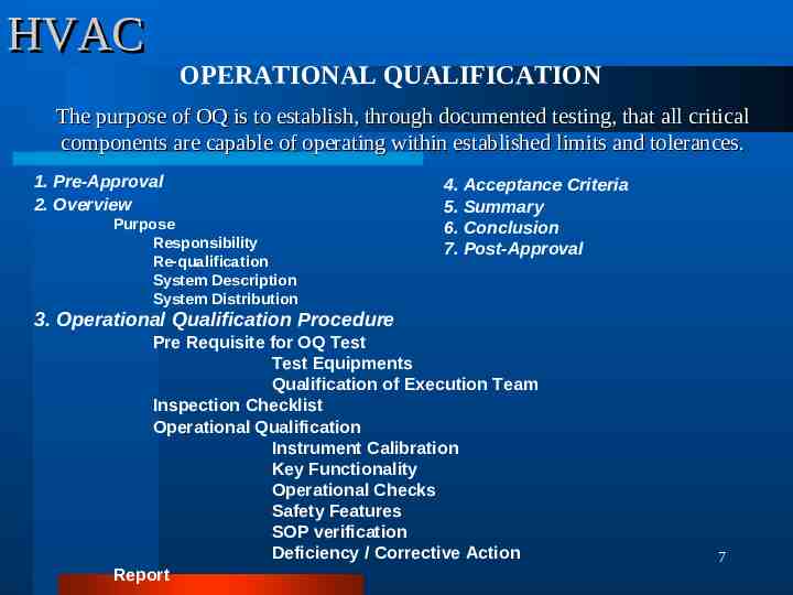
HVAC OPERATIONAL QUALIFICATION The purpose of OQ is to establish, through documented testing, that all critical components are capable of operating within established limits and tolerances. 1. Pre-Approval 2. Overview Purpose Responsibility Re-qualification System Description System Distribution 4. Acceptance Criteria 5. Summary 6. Conclusion 7. Post-Approval 3. Operational Qualification Procedure Pre Requisite for OQ Test Test Equipments Qualification of Execution Team Inspection Checklist Operational Qualification Instrument Calibration Key Functionality Operational Checks Safety Features SOP verification Deficiency / Corrective Action Report 7
HVAC PERFORMANCE QUALIFICATION The purpose of PQ is to verify and document that an HVAC system provides acceptable operational control under ‘ full operational ‘ conditions. 1. Pre-Approval 2. Overview Purpose Responsibility Re-qualification System Description System Distribution 3. Performance Qualification Procedure 3.1 Unit 3.2 3.3 3.4 3.5 3.6 3.7 3.8 3.9 3.10 3.11 Validation Re-qualification Frequency Validation Test Procedure Qualification of Execution team Test Instrument Calibration Record Pressure Drop across the HEPA and Fine filters of Air Handling Air Velocity Measurement and Calculation of Air Changes Integrity test of HEPA filters Differential Pressure Test Temperature and Relative Humidity Test Air Flow Direction Test Cleanliness Class Verification (Non viable Particle Count) Sound level Test Light Level Test Air Borne Viable Particle Monitoring Recovery test 8
HVAC Re-qualification Scheduled Qualification Scheduled qualifications as per validation plan shall be carried out. Unscheduled Qualification shall be carried out incase of Substitution of existing HVAC system with a new system. Replacement of existing HEPA-Filter or critical component. Any major modification to the existing HVAC system since purchase or after the last performance qualification. Frequent surpassing of the alert or action limits of routine environmental monitoring parameters 9
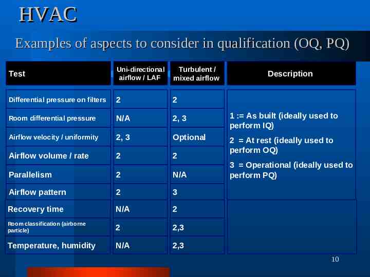
HVAC Examples of aspects to consider in qualification (OQ, PQ) Test Uni-directional airflow / LAF Turbulent / mixed airflow Differential pressure on filters 2 2 Room differential pressure N/A 2, 3 1 : As built (ideally used to perform IQ) Airflow velocity / uniformity 2, 3 Optional Airflow volume / rate 2 2 2 At rest (ideally used to perform OQ) Parallelism 2 N/A Airflow pattern 2 3 Recovery time N/A 2 Room classification (airborne particle) 2 2,3 Temperature, humidity N/A 2,3 Description 3 Operational (ideally used to perform PQ) 10
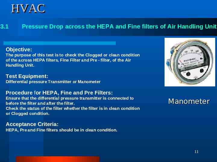
HVAC 3.1 Pressure Drop across the HEPA and Fine filters of Air Handling Unit Objective: The purpose of this test is to check the Clogged or clean condition of the across HEPA filters, Fine Filter and Pre - filter, of the Air Handling Unit. Test Equipment: Differential pressure Transmitter or Manometer Procedure for HEPA, Fine and Pre Filters: Ensure that the differential pressure transmitter is connected to before the filter and after the filter. Check the status of the filter whether the filter is in clean condition or Clogged condition. Manometer Acceptance Criteria: HEPA, Pre and Fine filters should be in clean condition. 11
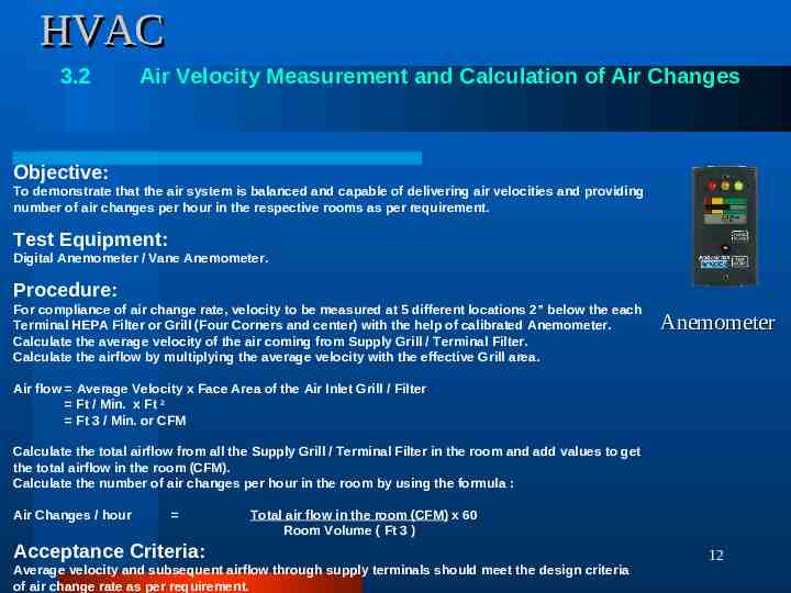
HVAC 3.2 Air Velocity Measurement and Calculation of Air Changes Objective: To demonstrate that the air system is balanced and capable of delivering air velocities and providing number of air changes per hour in the respective rooms as per requirement. Test Equipment: Digital Anemometer / Vane Anemometer. Procedure: For compliance of air change rate, velocity to be measured at 5 different locations 2” below the each Terminal HEPA Filter or Grill (Four Corners and center) with the help of calibrated Anemometer. Calculate the average velocity of the air coming from Supply Grill / Terminal Filter. Calculate the airflow by multiplying the average velocity with the effective Grill area. Anemometer Air flow Average Velocity x Face Area of the Air Inlet Grill / Filter Ft / Min. x Ft 2 Ft 3 / Min. or CFM Calculate the total airflow from all the Supply Grill / Terminal Filter in the room and add values to get the total airflow in the room (CFM). Calculate the number of air changes per hour in the room by using the formula : Air Changes / hour Total air flow in the room (CFM) x 60 Room Volume ( Ft 3 ) Acceptance Criteria: Average velocity and subsequent airflow through supply terminals should meet the design criteria of air change rate as per requirement. 12
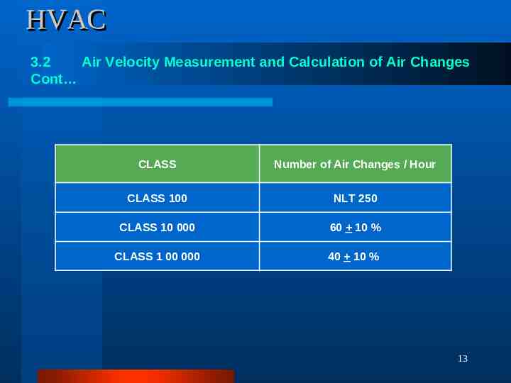
HVAC 3.2 Air Velocity Measurement and Calculation of Air Changes Cont CLASS Number of Air Changes / Hour CLASS 100 NLT 250 CLASS 10 000 60 10 % CLASS 1 00 000 40 10 % 13
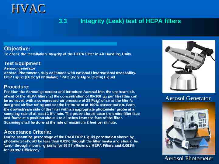
HVAC 3.3 Integrity (Leak) test of HEPA filters Objective: To check the installation integrity of the HEPA Filter in Air Handling Units. Test Equipment: Aerosol generator Aerosol Photometer, duly calibrated with national / international traceability. DOP Liquid (Di Octyl Phthalate) / PAO (Poly Alpha Olefin) Liquid Procedure: Position the Aerosol generator and introduce Aerosol into the upstream air, ahead of the HEPA filters, at the concentration of 80-100 g per liter (this can be achieved with a compressed air pressure of 25 Psig) of air at the filter’s designed airflow rating and set the instrument at 100% concentration. Scan the downstream side of the filter with an appropriate photometer probe at a sampling rate of at least 1 ft 3 / min. The probe should scan the entire filter face and frame at a position about 1 to 2 inches from the face of the filter. Scanning shall be done at the rate of maximum 2 feet per minute. Aerosol Generator Acceptance Criteria: During scanning percentage of the PAO/ DOP Liquid penetration shown by photometer should be less than 0.01% through the filter media and should be ‘zero’ through mounting joints for 99.97 efficiency HEPA Filters and 0.001% for 99.997 Efficiency. 14 Aerosol Photometer
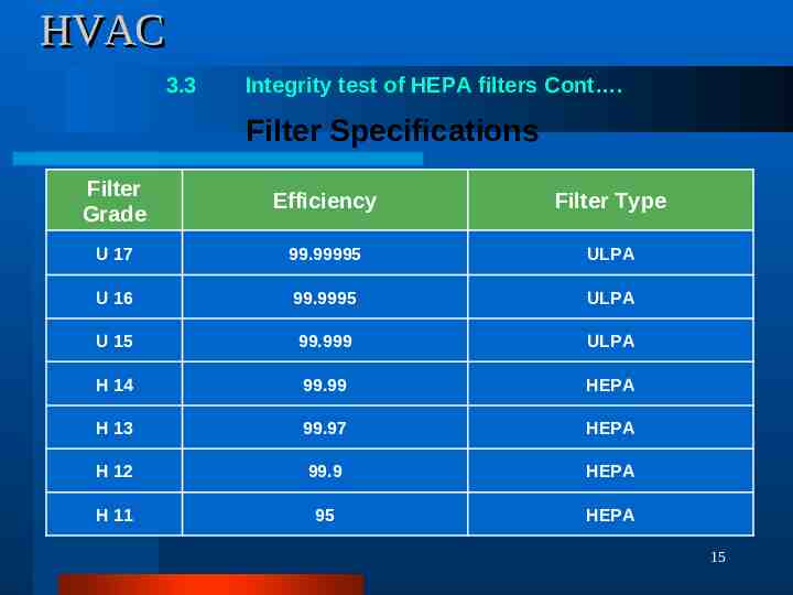
HVAC 3.3 Integrity test of HEPA filters Cont . Filter Specifications Filter Grade Efficiency Filter Type U 17 99.99995 ULPA U 16 99.9995 ULPA U 15 99.999 ULPA H 14 99.99 HEPA H 13 99.97 HEPA H 12 99.9 HEPA H 11 95 HEPA 15
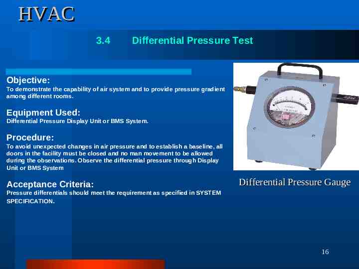
HVAC 3.4 Differential Pressure Test Objective: To demonstrate the capability of air system and to provide pressure gradient among different rooms. Equipment Used: Differential Pressure Display Unit or BMS System. Procedure: To avoid unexpected changes in air pressure and to establish a baseline, all doors in the facility must be closed and no man movement to be allowed during the observations. Observe the differential pressure through Display Unit or BMS System Acceptance Criteria: Differential Pressure Gauge Pressure differentials should meet the requirement as specified in SYSTEM SPECIFICATION. 16
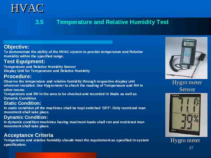
HVAC 3.5 Temperature and Relative Humidity Test Objective: To demonstrate the ability of the HVAC system to provide temperature and Relative Humidity within the specified range. Test Equipment: Temperature and Relative Humidity Sensor Display Unit for Temperature and Relative Humidity Procedure: Observe the temperature and relative humidity through respective display unit wherever installed. Use Hygrometer to check the reading of Temperature and RH in other rooms. Temperature and RH in the area to be checked and recorded in Static as well as Dynamic Condition. Hygro meter Sensor Static Condition: In static condition all the machines shall be kept switched ‘OFF’. Only restricted man movement shall take place. Dynamic Condition: In dynamic condition machines having maximum loads shall run and restricted man movement shall take place. Acceptance Criteria Temperature and relative humidity should meet the requirement as specified in system specification. Hygro meter 17
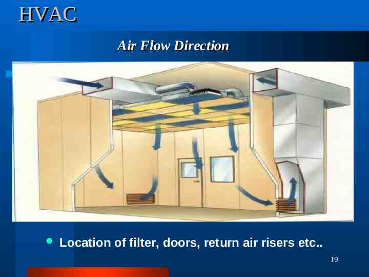
HVAC 3.6 Air Flow Direction Test Objective To ensure that the HFC system in aseptic area, LAF and Pass box provide unidirectional airflow up to the working height during rest and operating condition. To demonstrate that the air pressure is balanced and air is flowing from high-pressure zone to low pressure zone. Procedure Unidirectional Air Flow Area: Static Condition in Unidirectional Air Flow Area: Under HFC, no specific operation shall be carried out except Air Flow Pattern Test Place a torch of Dry Ice / TiCl4 under HFC. Observe the flow of Dry Ice / TiCl4 smoke at the filter downstream. Videotape the smoke flow pattern. Dynamic Condition in Unidirectional Air Flow Area: During operation place a torch of Dry Ice / TiCl4 under HFC. Observe the flow of Dry Ice / TiCl4 smoke at the filter downstream. Videotape the smoke flow pattern. Non Unidirectional Air Flow Area: Place the torch of Dry Ice / TiCl4 in between two rooms in door open condition. Observe the flow of Dry Ice / TiCl4 smoke between the rooms. Videotape / Photograph the smoke flow pattern. Acceptance Criteria Under HFC, Smoke Flow should be unidirectional up to working height Smoke should flow from the higher-pressure zone to low-pressure zone between the rooms when the door is open. 18
HVAC Air Flow Direction Location of filter, doors, return air risers etc. 19
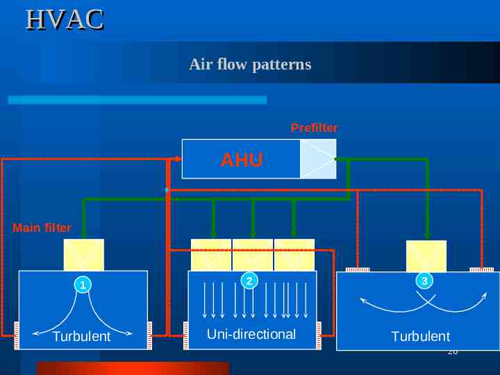
HVAC Air flow patterns Prefilter AHU Main filter 1 2 Turbulent Uni-directional 3 Turbulent 20
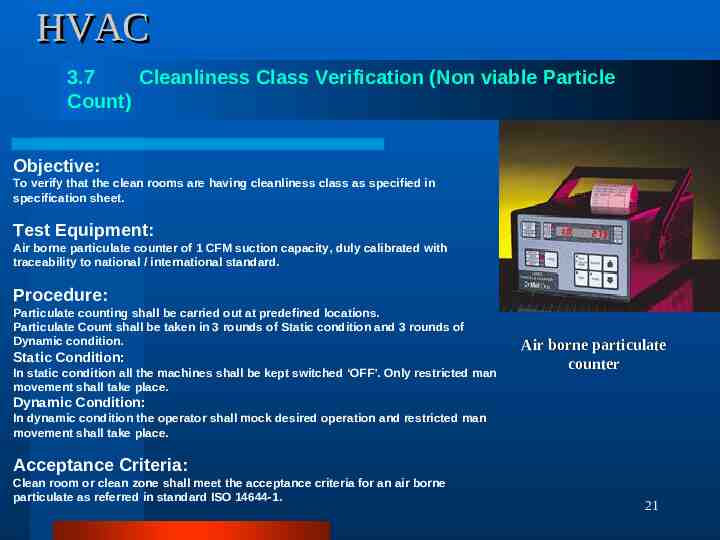
HVAC 3.7 Cleanliness Class Verification (Non viable Particle Count) Objective: To verify that the clean rooms are having cleanliness class as specified in specification sheet. Test Equipment: Air borne particulate counter of 1 CFM suction capacity, duly calibrated with traceability to national / international standard. Procedure: Particulate counting shall be carried out at predefined locations. Particulate Count shall be taken in 3 rounds of Static condition and 3 rounds of Dynamic condition. Static Condition: In static condition all the machines shall be kept switched ‘OFF’. Only restricted man movement shall take place. Air borne particulate counter Dynamic Condition: In dynamic condition the operator shall mock desired operation and restricted man movement shall take place. Acceptance Criteria: Clean room or clean zone shall meet the acceptance criteria for an air borne particulate as referred in standard ISO 14644-1. 21
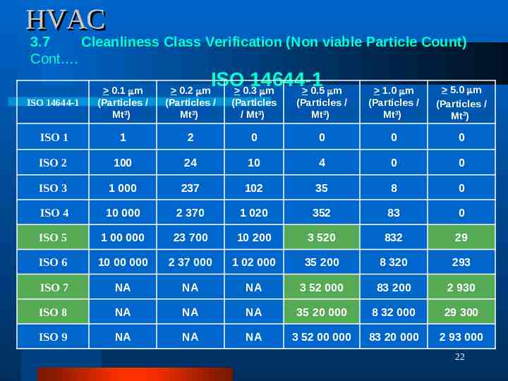
HVAC 3.7 Cleanliness Class Verification (Non viable Particle Count) Cont . ISO 14644-1 0.3 m 0.5 m (Particles / Mt3) 1.0 m (Particles / Mt3) 5.0 m (Particles / Mt3) 0 0 0 0 24 10 4 0 0 1 000 237 102 35 8 0 ISO 4 10 000 2 370 1 020 352 83 0 ISO 5 1 00 000 23 700 10 200 3 520 832 29 ISO 6 10 00 000 2 37 000 1 02 000 35 200 8 320 293 ISO 7 NA NA NA 3 52 000 83 200 2 930 ISO 8 NA NA NA 35 20 000 8 32 000 29 300 ISO 9 NA NA NA 3 52 00 000 83 20 000 2 93 000 ISO 14644-1 0.1 m (Particles / Mt3) 0.2 m (Particles / Mt3) (Particles / Mt3) ISO 1 1 2 ISO 2 100 ISO 3 22
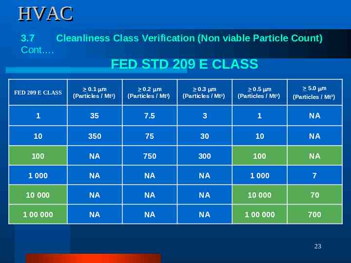
HVAC 3.7 Cleanliness Class Verification (Non viable Particle Count) Cont . FED STD 209 E CLASS FED 209 E CLASS 0.1 m (Particles / Mt3) 0.2 m (Particles / Mt3) 0.3 m (Particles / Mt3) 0.5 m (Particles / Mt3) 5.0 m (Particles / Mt3) 1 35 7.5 3 1 NA 10 350 75 30 10 NA 100 NA 750 300 100 NA 1 000 NA NA NA 1 000 7 10 000 NA NA NA 10 000 70 1 00 000 NA NA NA 1 00 000 700 23
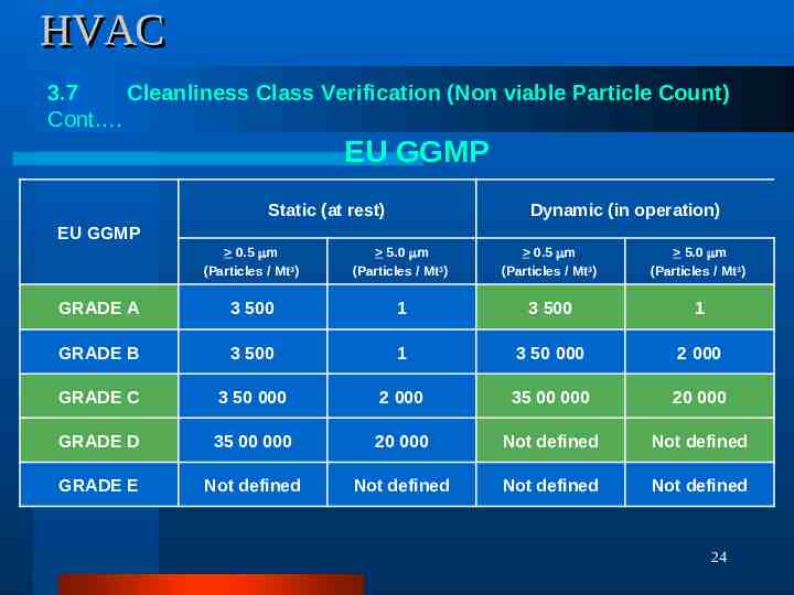
HVAC 3.7 Cleanliness Class Verification (Non viable Particle Count) Cont . EU GGMP Static (at rest) Dynamic (in operation) EU GGMP 0.5 m (Particles / Mt3) 5.0 m (Particles / Mt3) 0.5 m (Particles / Mt3) 5.0 m (Particles / Mt3) GRADE A 3 500 1 3 500 1 GRADE B 3 500 1 3 50 000 2 000 GRADE C 3 50 000 2 000 35 00 000 20 000 GRADE D 35 00 000 20 000 Not defined Not defined GRADE E Not defined Not defined Not defined Not defined 24
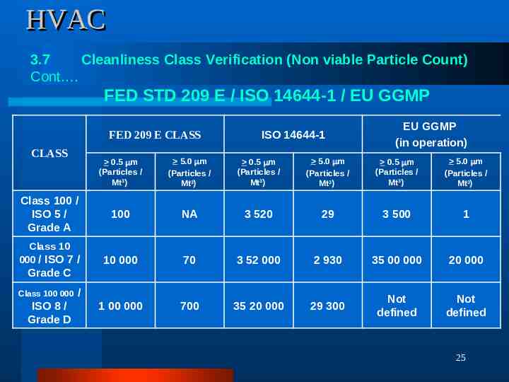
HVAC 3.7 Cleanliness Class Verification (Non viable Particle Count) Cont . FED STD 209 E / ISO 14644-1 / EU GGMP FED 209 E CLASS CLASS Class 100 / ISO 5 / Grade A Class 10 000 / ISO 7 / ISO 14644-1 EU GGMP (in operation) 0.5 m (Particles / Mt3) 5.0 m (Particles / Mt3) 0.5 m (Particles / Mt3) 5.0 m (Particles / Mt3) 0.5 m (Particles / Mt3) 5.0 m (Particles / Mt3) 100 NA 3 520 29 3 500 1 10 000 70 3 52 000 2 930 35 00 000 20 000 1 00 000 700 35 20 000 29 300 Not defined Not defined Grade C Class 100 000 ISO 8 / Grade D / 25
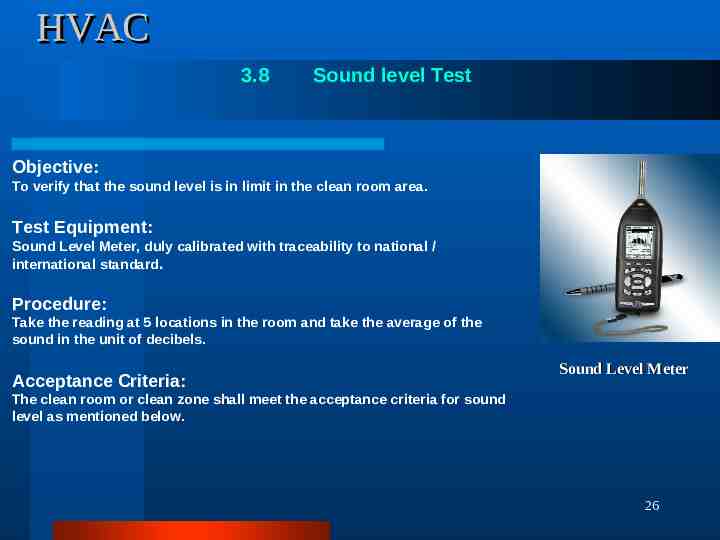
HVAC 3.8 Sound level Test Objective: To verify that the sound level is in limit in the clean room area. Test Equipment: Sound Level Meter, duly calibrated with traceability to national / international standard. Procedure: Take the reading at 5 locations in the room and take the average of the sound in the unit of decibels. Acceptance Criteria: Sound Level Meter The clean room or clean zone shall meet the acceptance criteria for sound level as mentioned below. 26
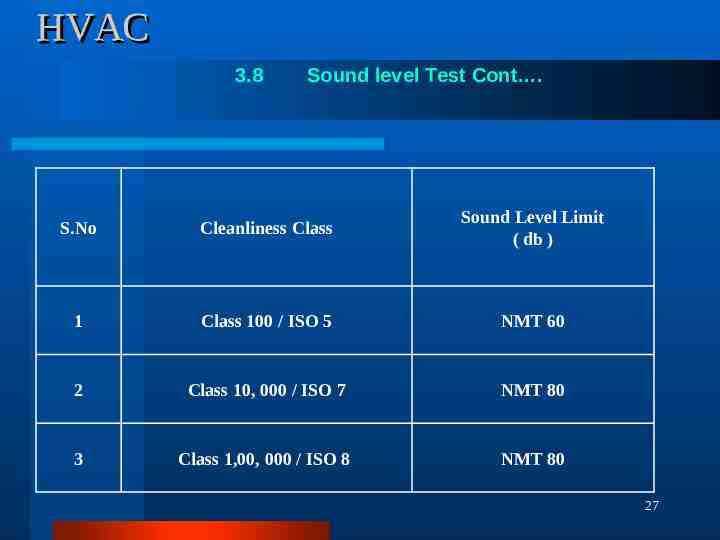
HVAC 3.8 Sound level Test Cont . S.No Cleanliness Class Sound Level Limit ( db ) 1 Class 100 / ISO 5 NMT 60 2 Class 10, 000 / ISO 7 NMT 80 3 Class 1,00, 000 / ISO 8 NMT 80 27
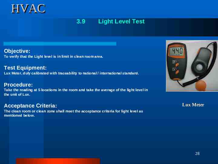
HVAC 3.9 Light Level Test Objective: To verify that the Light level is in limit in clean room area. Test Equipment: Lux Meter, duly calibrated with traceability to national / international standard. Procedure: Take the reading at 5 locations in the room and take the average of the light level in the unit of Lux. Acceptance Criteria: Lux Meter The clean room or clean zone shall meet the acceptance criteria for light level as mentioned below. 28
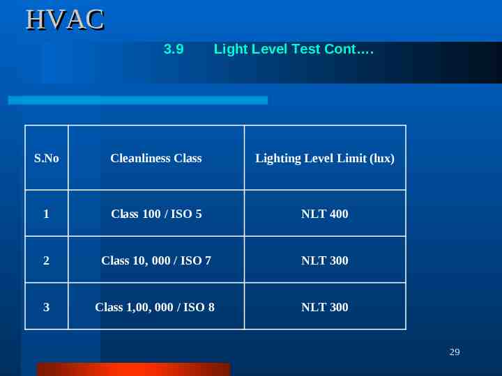
HVAC 3.9 Light Level Test Cont . S.No Cleanliness Class Lighting Level Limit (lux) 1 Class 100 / ISO 5 NLT 400 2 Class 10, 000 / ISO 7 NLT 300 3 Class 1,00, 000 / ISO 8 NLT 300 29
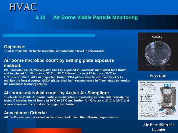
HVAC 3.10 Air Borne Viable Particle Monitoring Objective: To determine the air borne microbial contamination level in critical area. Air borne microbial count by settling plate exposure method: Pre incubated SCDA Media plates shall be exposed in Locations mentioned for 4 hours and incubated for 48 hours at 30 C to 35 C followed by next 72 hours at 20 C to 25 C.Record the results in respective format. PDA plates shall be exposed weekly to monitor the fungal counts. SCDA plates shall be incubated once in fifteen days to monitor the anaerobic Microorganisms Petri Dish Air borne microbial count by Active Air Sampling: To check the Viable Air borne particle count active air sampling is done and incubate the tested Cassettes for 48 hours at 30 C to 35 C and further for 72hours at 20 C to 25 C and observations are recorded in the respective format. Acceptance Criteria: All the Parameters performed in the area should meet the following requirements. Air Borne30Particle Counter
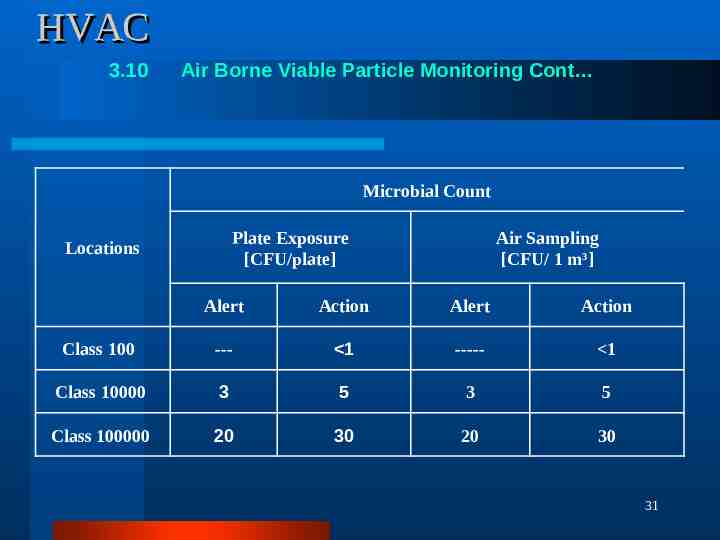
HVAC 3.10 Air Borne Viable Particle Monitoring Cont Microbial Count Plate Exposure [CFU/plate] Locations Air Sampling [CFU/ 1 m3] Alert Action Alert Action Class 100 --- 1 ----- 1 Class 10000 3 5 3 5 Class 100000 20 30 20 30 31
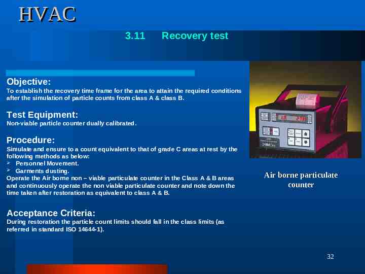
HVAC 3.11 Recovery test Objective: To establish the recovery time frame for the area to attain the required conditions after the simulation of particle counts from class A & class B. Test Equipment: Non-viable particle counter dually calibrated. Procedure: Simulate and ensure to a count equivalent to that of grade C areas at rest by the following methods as below: Personnel Movement. Garments dusting. Operate the Air borne non – viable particulate counter in the Class A & B areas and continuously operate the non viable particulate counter and note down the time taken after restoration as equivalent to class A & B. Air borne particulate counter Acceptance Criteria: During restoration the particle count limits should fall in the class limits (as referred in standard ISO 14644-1). 32
HVAC 33
HVAC 34
HVAC 35
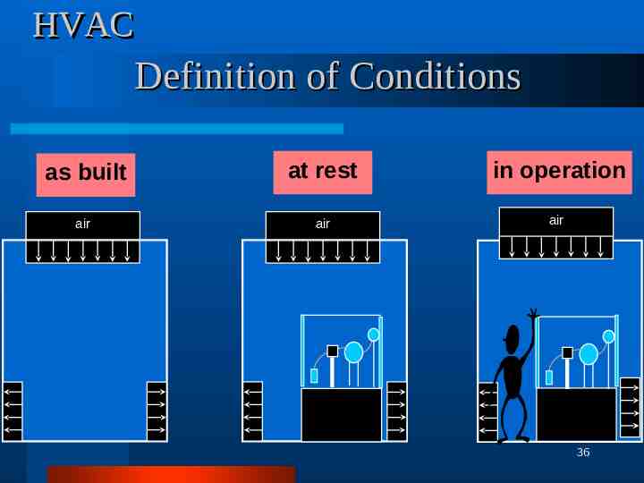
HVAC Definition of Conditions as built at rest in operation air air air 36
HVAC Q&A Than Q 37