TECO 7300EV VFD Quick Start


34 Slides439.00 KB
TECO 7300EV VFD Quick Start
But First RTFM
RTFM (Read The Frickin Manual) Manuals are always a problem. Some manuals are written by people who don’t really understand the device they’re documenting. Even worse are manuals written by someone who understands the device so well he skips over important basic information. Finally many seem to be written by people not fluent in the language of the manual.
ROTFM (Re-Organize The Frickin Manual) Best way to approach these manuals: – Skim first to understand organization Dog ear the most important sections and diagrams Highlight key information like important settings in charts or terminals on diagrams. Cross out or redact non-applicable material. – Go back and re-read in more depth the most important sections – Look for repeated information that may be presented differently. Hopefully this will help clarify things that you’re unsure of.
RWTFM (Re-Write The Frickin Manual) Add notes to the manual to clarify any confusing nomenclature. (e.g. NPN / PNP vs. Sink / Source) Add references to sections that should have been repeated. Write directly in the manual since you’ll probably be just as confused the next time you pick up the manual.
STFW (Search The Frickin Web) Finally, Don’t forget to check for newer or more detailed manuals on the manufacturer’s web site or on any CD that came with the device. Usually the printed manual is the worst version available. It’s not a bad idea to do a web search on the VFD model number to look for other versions of the manual. Sometimes resellers will publish their own version or a user will post a how-to guide.
KISS (Too much flexibility can be confusing) One common issue with today’s computercontrolled devices is the multitude of options and configuration settings. A good example of this is the control inputs on this TECO 7300EV VFD. – Instead of providing input connectors labeled “Start” and “Stop” the provide a set of 4 inputs that can be programmed to be “Stop”, Start”, “E-Stop”, “Reverse”, and so forth. – Obviously until you program the VFD you’re not likely to get your “Stop” control to do anything. – Or worse, it may do something other than stop!
Start simple and build out. Don’t try to set all configuration options at once. Get the basics working first then add the complexity needed for your machine. – Get the motor turning first with default settings for acceleration and frequency. – Once the motor is turning you can tune motor settings and set more arcane parameters. – Only after this should you add external controls. Since you often have ot modify additional parameters to make the controls function correctly doing this step last will help simplify things and isolate any problems that may occur.
Step 1 – Safety Check Double check VFD and motor ratings and verify you have appropriate gauge wire for the HP rating of the motor. Review and understand safety warnings.
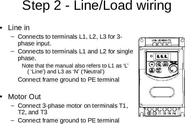
Step 2 - Line/Load wiring Line in – Connects to terminals L1, L2, L3 for 3phase input. – Connects to terminals L1 and L2 for single phase. Note that the manual also refers to L1 as ‘L’ ( ‘Line’) and L3 as ‘N’ (‘Neutral’) Connect frame ground to PE terminal Motor Out – Connect 3-phase motor on terminals T1, T2, and T3 – Connect frame ground to PE terminal
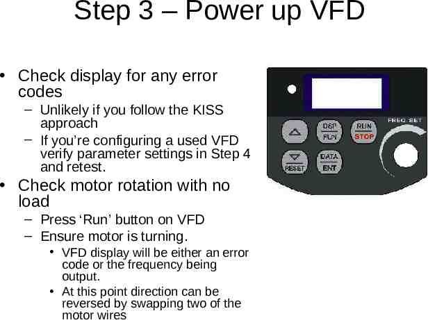
Step 3 – Power up VFD Check display for any error codes – Unlikely if you follow the KISS approach – If you’re configuring a used VFD verify parameter settings in Step 4 and retest. Check motor rotation with no load – Press ‘Run’ button on VFD – Ensure motor is turning. VFD display will be either an error code or the frequency being output. At this point direction can be reversed by swapping two of the motor wires
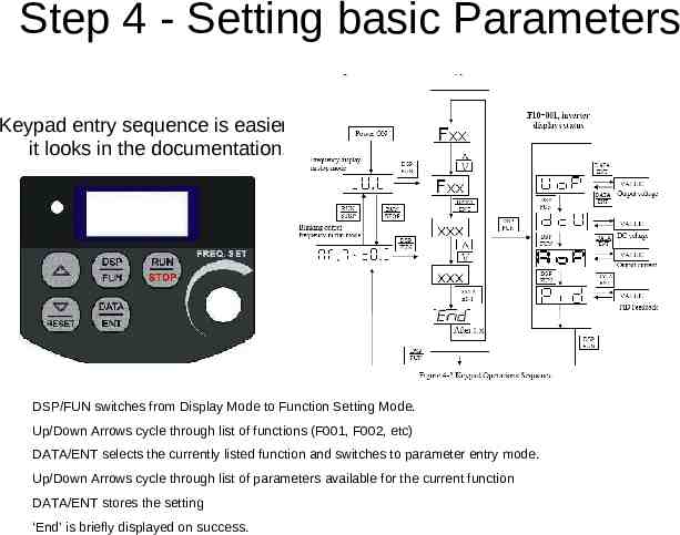
Step 4 - Setting basic Parameters Keypad entry sequence is easier than it looks in the documentation! DSP/FUN switches from Display Mode to Function Setting Mode. Up/Down Arrows cycle through list of functions (F001, F002, etc) DATA/ENT selects the currently listed function and switches to parameter entry mode. Up/Down Arrows cycle through list of parameters available for the current function DATA/ENT stores the setting ‘End’ is briefly displayed on success.
Step 4 - Setting basic Parameters Inverter rated current – Parameter F00 – Could more correctly be named “Inverter Model” instead Deceleration time – Parameter F02 – Depending on your machine 2-10 seconds may be reasonable Remember that quick stops may require adding a braking resistor! Stopping method (Parameter F09) A related setting that can be set to either decelerate or coast Acceleration time – Parameter F01 – Depending on your machine 2-5 seconds may be reasonable
Step 4 - Setting basic Parameters Upper frequency limit – Parameter F07 – 120Hz is reasonable upper limit for modern 1800 RPM motors 1HP as 3600 RPM should be within design limits. If in doubt check the motor specs. Lower frequency limit – Parameter F07 – 20Hz is as low as you should go. At low speeds torque and motor cooling become issues.
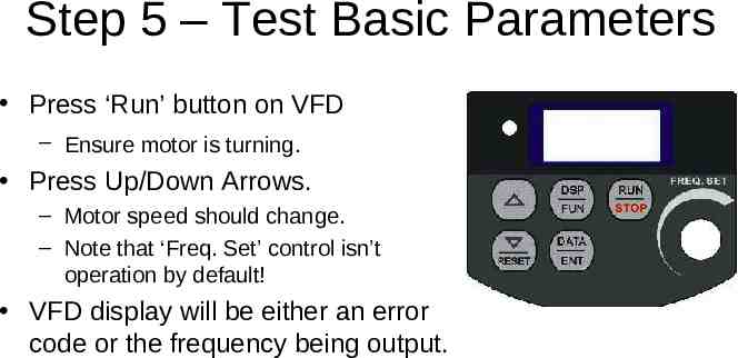
Step 5 – Test Basic Parameters Press ‘Run’ button on VFD – Ensure motor is turning. Press Up/Down Arrows. – Motor speed should change. – Note that ‘Freq. Set’ control isn’t operation by default! VFD display will be either an error code or the frequency being output.
Step 6 – Set Advanced Parameters When the VFD is set to run in Vector Mode additional motor parameters need to be set. Control mode (Parameter C14) Vector or V/Hz Motor Rated Current (Amps) (F43) Motor Rated Voltage (Volts) (F44) Motor Rated Frequency (Hz) (F45) Motor Rated Power (KW) (F46) Motor Rated Speed (RPM) (F47) Additional Vector Mode Settings to adjust for optimum operations are: – Torque boost gain (F48) – Slip compensation gain (F49) – Low Frequency Voltage Compensation (F50)
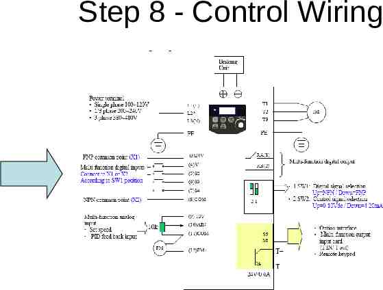
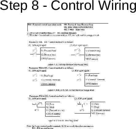
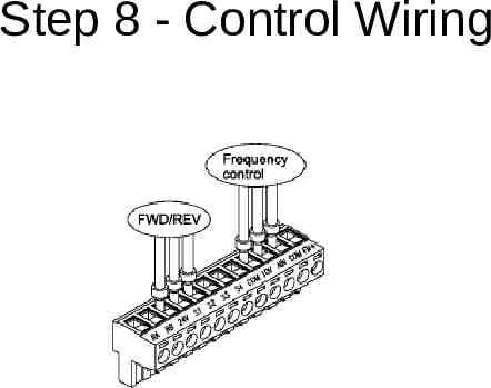
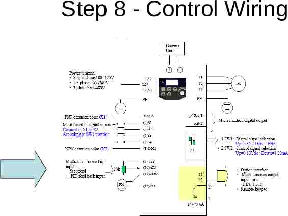
Step 7 - Parameters for Controls F04 Run signal source – 000: keypad – 001: External Terminal F06 : External control operation mode – 000: Forward/ Stop-Reverse/Stop – 001: Run/ Stop-Forward/Reverse – 002: 3-wire—Run/ Stop NB: 3-wire mode redefines inputs S1, S2 & S3!
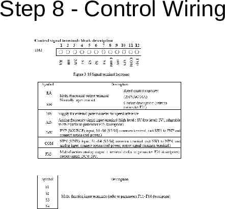
Step 7 - Parameters for Controls F11 15 Selectable Functions for input terminals ( S1-S4& AIN ) – – – – – – – – 000: Forward run 001: Reverse run 002: Preset speed command 1 003: Preset speed command 2 004: Preset speed command 3 005: Jog frequency command 006: External Emergency stop(E.S.) 017: Analog frequency signal input( terminal AIN)
Step 7 - Parameters for Controls F05 Frequency signal source – 000: UP/Down Key on keypad – 001: Potentiometer on keypad – 002: AIN input signal from (TM2) F16 AIN signal select – 000: 0 10V(0 20mA) – 001: 4 20mA(2 10V)
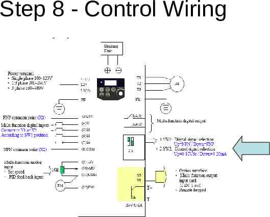
Step 8 - Control Wiring
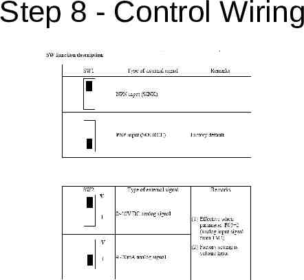
Step 8 - Control Wiring
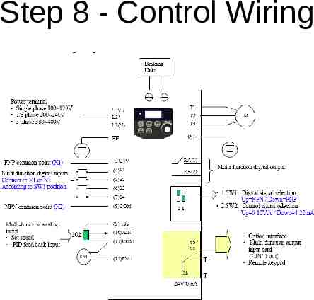
Step 8 - Control Wiring
Step 8 - Control Wiring
Step 8 - Control Wiring
Step 8 - Control Wiring
Step 8 - Control Wiring
Step 8 - Control Wiring
Step 8 - Control Wiring
Step 8 - Control Wiring
END
Vector vs. V/Hz A standard VFD (lets call it a Scalar Drive) puts out a PWM pattern designed to maintain a constant V/Hz pattern to the motor under ideal conditions. How the motor reacts to that PWM pattern is very dependent upon the load conditions. The Scalar drive knows nothing about that, it only tells the motor what to do. If for example it provides 43Hz to the motor, and the motor spins at a speed equivalent to 40Hz, the Scalar Drive doesn't know. You can't do true torque control with a scalar drive because it has no way of knowing what the motor output torque is (beyond an educated guess). These problems associated with the scalar VFDs inability to alter it's output with changes in the load gets worse as the speed reference goes down, so the "rule of thumb" in determining the need for which technology to use is that scalar drives work OK at speed ranges between 5:1 (50Hz applications) or 6:1 (60Hz applications). So if your application will need accurate control below 10Hz, scalar may not work for you.
Vector vs. V/Hz A Vector Drive uses feedback of various real world information (more on that later) to further modify the PWM pattern to maintain more precise control of the desired operating parameter, be it speed or torque. Using a more powerful and faster microprocessor, it uses the feedback information to calculate the exact vector of voltage and frequency to attain the goal. In a true closed loop fashion, it goes on to constantly update that vector to maintain it. It tells the motor what to do, then checks to see if it did it, then changes its command to correct for any error. Vector drives come in 2 types, Open Loop and Closed Loop, based upon the way they get their feedback information.
Vector vs. V/Hz A true Closed Loop Vector Drive uses a shaft encoder on the motor to give positive shaft position indication back to the microprocessor (mP). So when the mP says move x radians, the encoder says "it only moved x-2 radians". The mP then alters the PWM signature on the fly to make up for the error. For torque control, the feedback allows the mP to adjust the pattern so that a constant level of torque can be maintained regardless of speed, i.e. a winder application where diameters are constantly changing. If the shaft moves one way or the other too much, the torque requirement is wrong and the error is corrected. A true closed Loop Vector Drive can also make an AC motor develop continuous full torque at zero speed, something that previously only DC drives were capable of. That makes them suitable for crane and hoist applications where the motor must produce full torque before the brake is released or else the load begins dropping and it can't be stopped. Closed Loop is also so close to being a servo drive that some people use them as such. The shaft encoder can be used to provide precise travel feedback by counting pulses. (Note: See Addendum below for additional information)
Vector vs. V/Hz Open Loop is actually a misnomer because it is actually a closed loop system, but the feedback loop comes from within the VFD itself instead of an external encoder. For this reason there is a trend to refer to them as "Sensorless Vector" drives. The mP creates a mathematical "model" of the motor operating parameters and keeps it in memory. As the motor operates, the mP monitors the output current (mainly), compares it to the model and determines from experience what the different current effects mean in terms of the motor performance. Then the mP executes the necessary error corrections just as the closed Loop Vector Drive does. The only drawback is that as the motor gets slower, the ability of the mP to detect the subtle changes in magnetics becomes more difficult. At zero speed it is generally accepted that an Open loop Vector Drive is not reliable enough to use on cranes and hoists. For most other applications though it is just fine. This is all done at very high speeds, that is why you did not see Vector Drives as available earlier on. The cost of the high speed micro processor technology has now come down to every day availability.