SOLID STATE DRIVES UNIT 4: SYNCHRONOUS MOTOR DRIVES 1

29 Slides2.07 MB
SOLID STATE DRIVES UNIT 4: SYNCHRONOUS MOTOR DRIVES 1
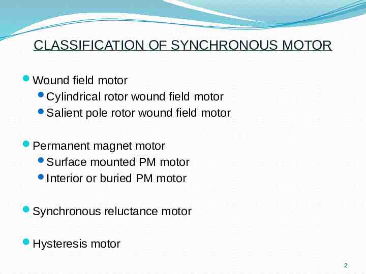
CLASSIFICATION OF SYNCHRONOUS MOTOR Wound field motor Cylindrical rotor wound field motor Salient pole rotor wound field motor Permanent magnet motor Surface mounted PM motor Interior or buried PM motor Synchronous reluctance motor Hysteresis motor 2
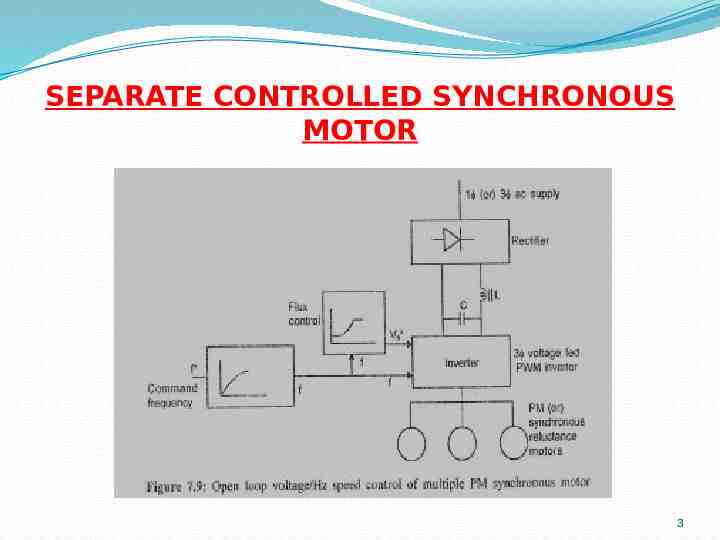
SEPARATE CONTROLLED SYNCHRONOUS MOTOR 3
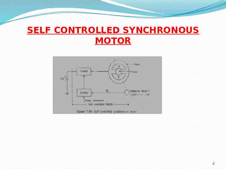
SELF CONTROLLED SYNCHRONOUS MOTOR 4
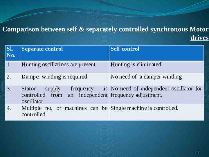
Comparison between self & separately controlled synchronous Motor drives Sl. No. Separate control Self control 1. Hunting oscillations are present Hunting is eliminated 2. Damper winding is required No need of a damper winding 3. Stator supply frequency is No need of independent oscillator for controlled from an independent frequency adjustment. oscillator Multiple no. of machines can be Single machine is controlled. controlled. 4. 5
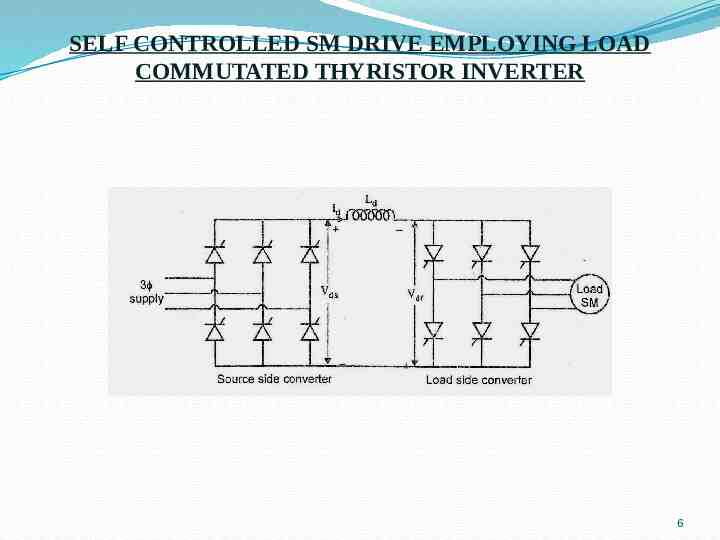
SELF CONTROLLED SM DRIVE EMPLOYING LOAD COMMUTATED THYRISTOR INVERTER 6
VOLTAGE SOURCE INVERTER (VSI) FED SM Three ways of producing VVVF supply using VSI: 1. Square wave inverters 2. PWM inverters 3. Chopper with square wave inverters In all the cases the SM can be operated either in self or separate controlled mode 7
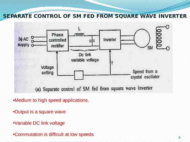
SEPARATE CONTROL OF SM FED FROM SQUARE WAVE INVERTER Medium to high speed applications. Output is a square wave Variable DC link voltage Commutation is difficult at low speeds 8
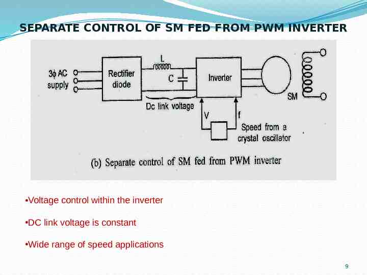
SEPARATE CONTROL OF SM FED FROM PWM INVERTER Voltage control within the inverter DC link voltage is constant Wide range of speed applications 9
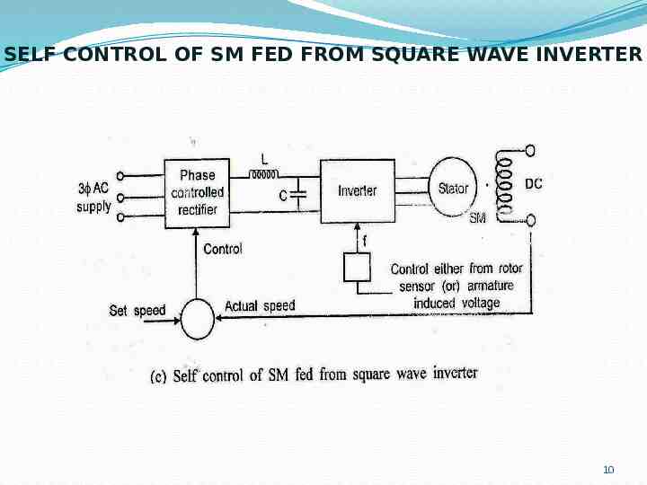
SELF CONTROL OF SM FED FROM SQUARE WAVE INVERTER 10
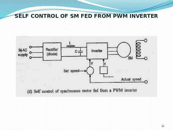
SELF CONTROL OF SM FED FROM PWM INVERTER 11
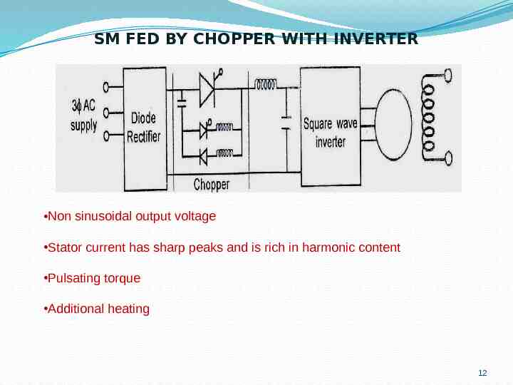
SM FED BY CHOPPER WITH INVERTER Non sinusoidal output voltage Stator current has sharp peaks and is rich in harmonic content Pulsating torque Additional heating 12
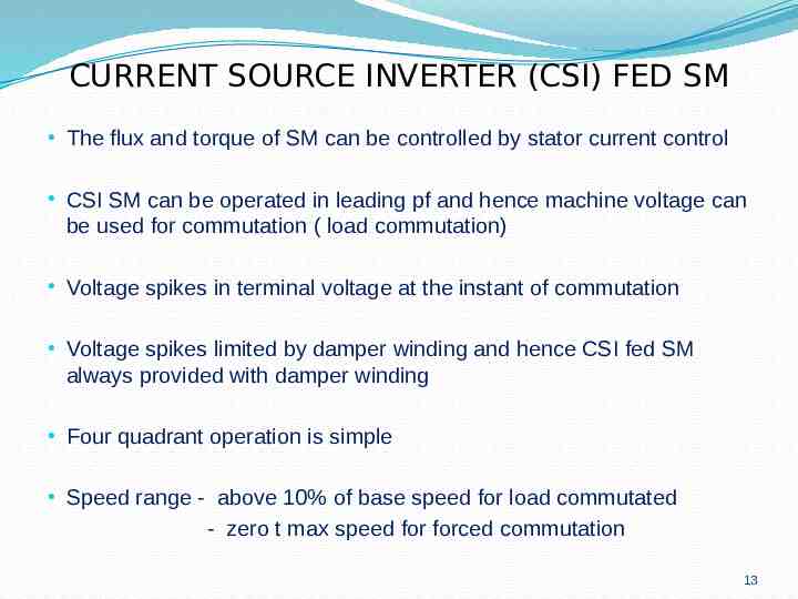
CURRENT SOURCE INVERTER (CSI) FED SM The flux and torque of SM can be controlled by stator current control CSI SM can be operated in leading pf and hence machine voltage can be used for commutation ( load commutation) Voltage spikes in terminal voltage at the instant of commutation Voltage spikes limited by damper winding and hence CSI fed SM always provided with damper winding Four quadrant operation is simple Speed range - above 10% of base speed for load commutated - zero t max speed for forced commutation 13
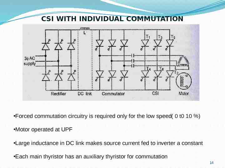
CSI WITH INDIVIDUAL COMMUTATION Forced commutation circuitry is required only for the low speed( 0 t0 10 %) Motor operated at UPF Large inductance in DC link makes source current fed to inverter a constant Each main thyristor has an auxiliary thyristor for commutation 14
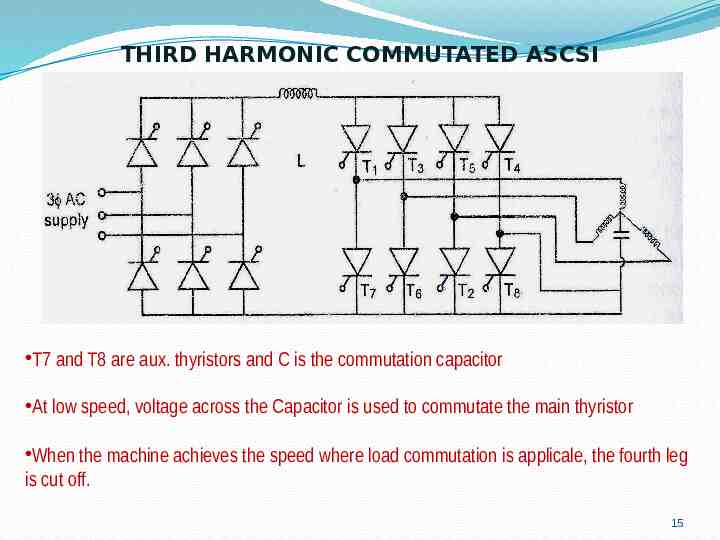
THIRD HARMONIC COMMUTATED ASCSI T7 and T8 are aux. thyristors and C is the commutation capacitor At low speed, voltage across the Capacitor is used to commutate the main thyristor When the machine achieves the speed where load commutation is applicale, the fourth leg is cut off. 15
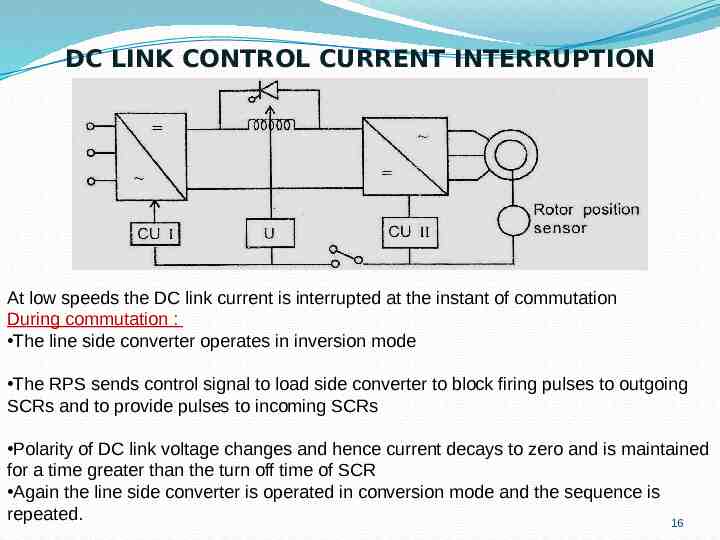
DC LINK CONTROL CURRENT INTERRUPTION At low speeds the DC link current is interrupted at the instant of commutation During commutation : The line side converter operates in inversion mode The RPS sends control signal to load side converter to block firing pulses to outgoing SCRs and to provide pulses to incoming SCRs Polarity of DC link voltage changes and hence current decays to zero and is maintained for a time greater than the turn off time of SCR Again the line side converter is operated in conversion mode and the sequence is repeated. 16
CYCLOCONVERTER FED SM (SELF CONTROL) 17
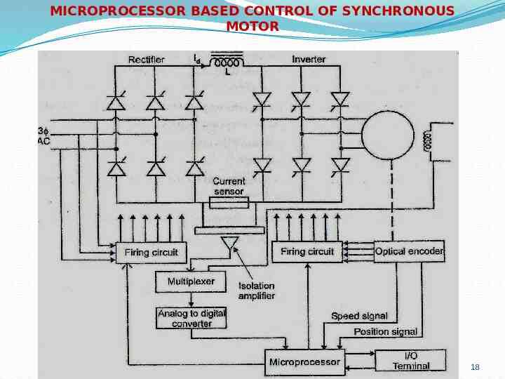
MICROPROCESSOR BASED CONTROL OF SYNCHRONOUS MOTOR 18
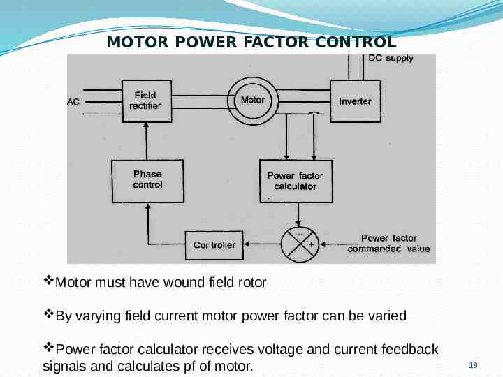
MOTOR POWER FACTOR CONTROL Motor must have wound field rotor By varying field current motor power factor can be varied Power factor calculator receives voltage and current feedback signals and calculates pf of motor. 19
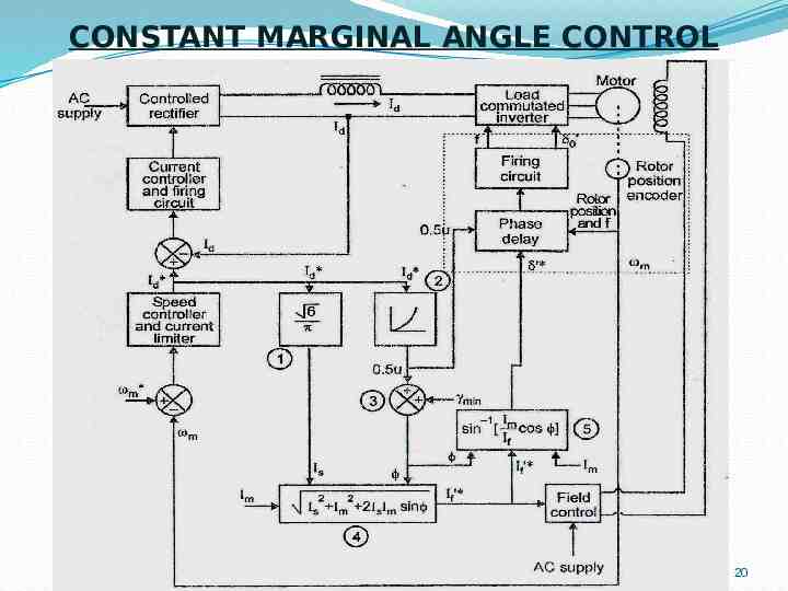
CONSTANT MARGINAL ANGLE CONTROL 20
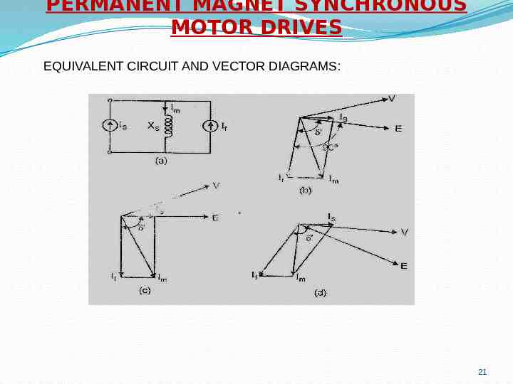
PERMANENT MAGNET SYNCHRONOUS MOTOR DRIVES EQUIVALENT CIRCUIT AND VECTOR DIAGRAMS: 21
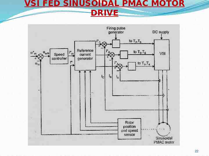
VSI FED SINUSOIDAL PMAC MOTOR DRIVE 22
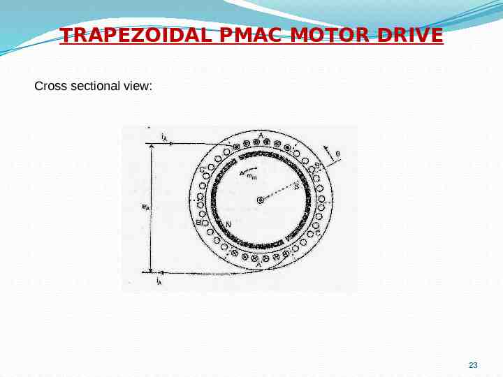
TRAPEZOIDAL PMAC MOTOR DRIVE Cross sectional view: 23
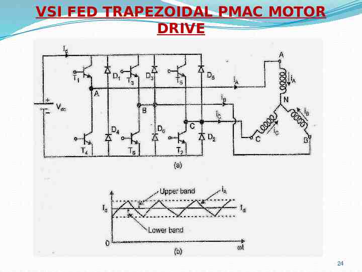
VSI FED TRAPEZOIDAL PMAC MOTOR DRIVE 24
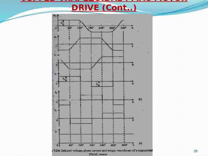
VSI FED TRAPEZOIDAL PMAC MOTOR DRIVE (Cont.) 25
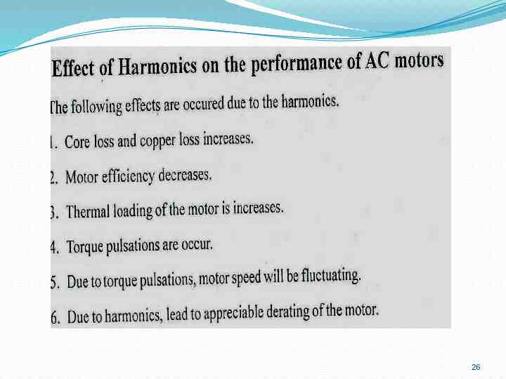
26
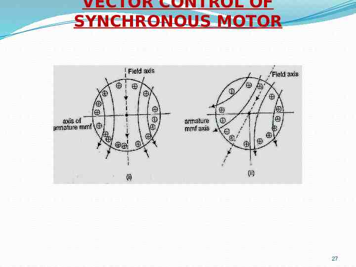
VECTOR CONTROL OF SYNCHRONOUS MOTOR 27
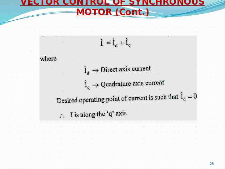
VECTOR CONTROL OF SYNCHRONOUS MOTOR (Cont.) 28
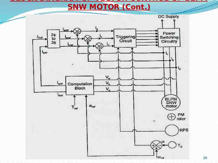
BLOCK DIAGRAM OF VECTOR CONTROL OF BLPM SNW MOTOR (Cont.) 29