Kollmorgen Frameless Motor Mounting Practices Bonding with Structural
15 Slides5.39 MB
Kollmorgen Frameless Motor Mounting Practices Bonding with Structural Adhesives April 2012 1
Mounting Considerations Embedded Motion Technology Frameless Mounting Considerations The benefits of Improved System Performance, Reduced Maintenance, Smaller Mechanical Footprint, Higher System Efficiency are understood Customer still has a key question in mind I like the frameless design concept but how do I mount the motor components into my machine? 2 2
Mounting Considerations Mechanical Mounting Considerations Customer’s own bearings Customer’s shafting / drivetrain Bearing precision and machining tolerances are dependent more on customer machine requirements than frameless motor mounting requirements Run-out more dependent on customer requirements Air gap of 0.015” – 0.075” (0.38 mm – 1.9 mm) each side of 3 rotor needed for frameless motor Mounting; Bonding, Clamping, and Shrink fit options discussed in some detail in the KBM Selection Guide 3
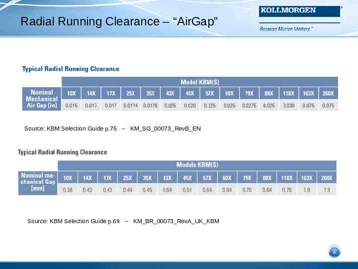
Radial Running Clearance – “AirGap” Source: KBM Selection Guide p.75 – KM SG 00073 RevB EN 4 Source: KBM Selection Guide p.69 – KM BR 00073 RevA UK KBM 4
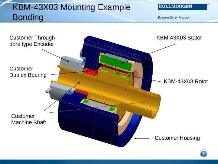
KBM-43X03 Mounting Example Bonding Customer Throughbore type Encoder KBM-43X03 Stator Customer Duplex Bearing KBM-43X03 Rotor Customer Machine Shaft 5 Customer Housing 5
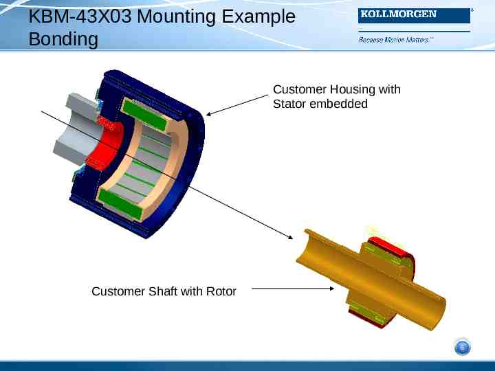
KBM-43X03 Mounting Example Bonding Customer Housing with Stator embedded Customer Shaft with Rotor 6 6
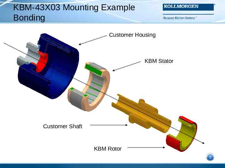
KBM-43X03 Mounting Example Bonding Customer Housing KBM Stator Customer Shaft 7 KBM Rotor 7
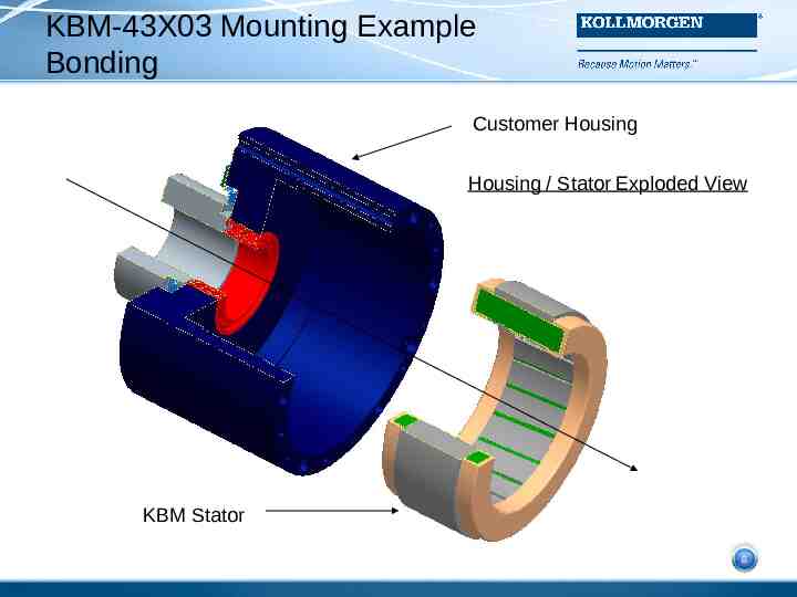
KBM-43X03 Mounting Example Bonding Customer Housing Housing / Stator Exploded View 8 KBM Stator 8
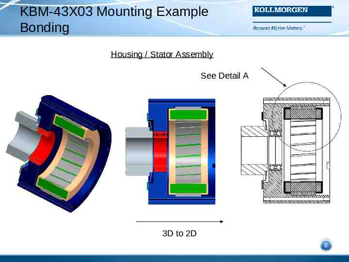
KBM-43X03 Mounting Example Bonding Housing / Stator Assembly See Detail A 9 3D to 2D 9
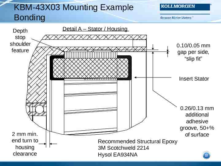
KBM-43X03 Mounting Example Bonding Depth stop shoulder feature Detail A – Stator / Housing 0.10/0.05 mm gap per side, “slip fit” Insert Stator 2 mm min. end turn to housing clearance 0.26/0.13 mm additional adhesive groove, 50 % 10 of surface Recommended Structural Epoxy 3M Scotchweld 2214 Hysol EA934NA 10
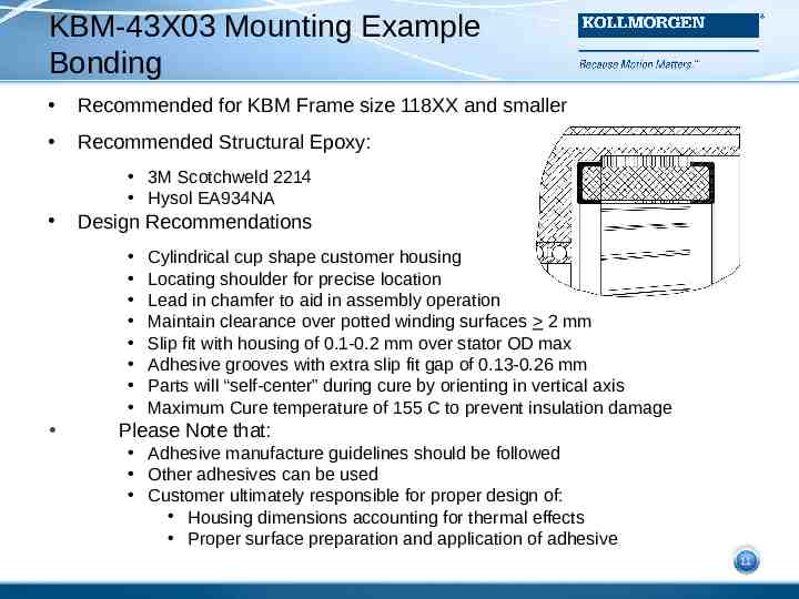
KBM-43X03 Mounting Example Bonding Recommended for KBM Frame size 118XX and smaller Recommended Structural Epoxy: 3M Scotchweld 2214 Hysol EA934NA Design Recommendations Cylindrical cup shape customer housing Locating shoulder for precise location Lead in chamfer to aid in assembly operation Maintain clearance over potted winding surfaces 2 mm Slip fit with housing of 0.1-0.2 mm over stator OD max Adhesive grooves with extra slip fit gap of 0.13-0.26 mm Parts will “self-center” during cure by orienting in vertical axis Maximum Cure temperature of 155 C to prevent insulation damage Please Note that: Adhesive manufacture guidelines should be followed Other adhesives can be used Customer ultimately responsible for proper design of: Housing dimensions accounting for thermal effects Proper surface preparation and application of adhesive 11 11
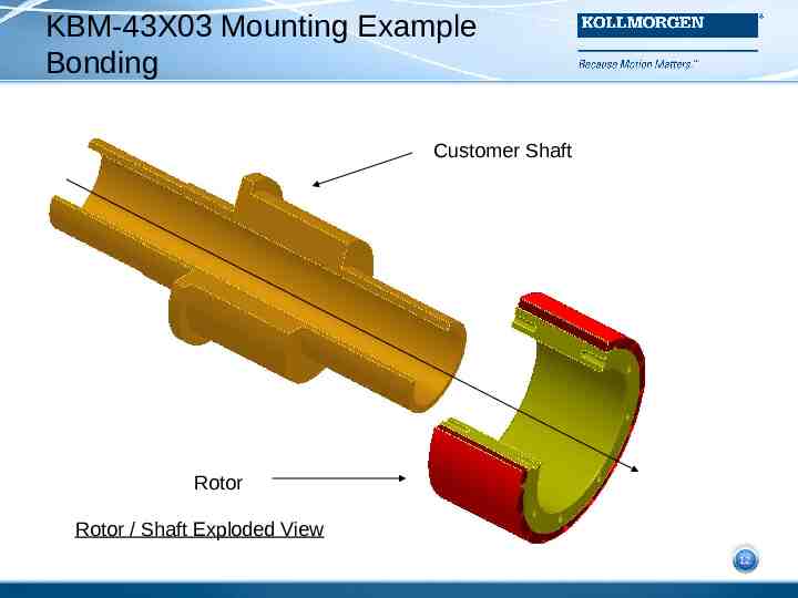
KBM-43X03 Mounting Example Bonding Customer Shaft Rotor 12 Rotor / Shaft Exploded View 12
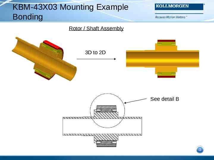
KBM-43X03 Mounting Example Bonding Rotor / Shaft Assembly 3D to 2D See detail B 13 13
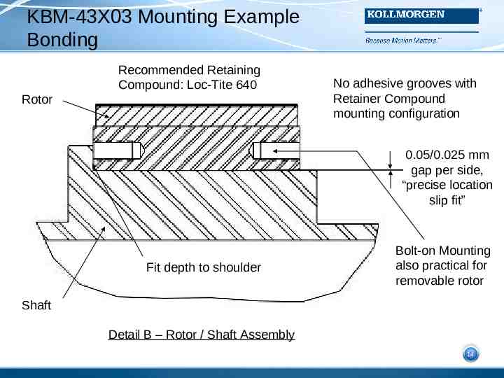
KBM-43X03 Mounting Example Bonding Recommended Retaining Compound: Loc-Tite 640 Rotor No adhesive grooves with Retainer Compound mounting configuration 0.05/0.025 mm gap per side, “precise location slip fit” Fit depth to shoulder Bolt-on Mounting also practical for removable rotor 14 Shaft Detail B – Rotor / Shaft Assembly 14
Mounting Considerations Bonding with Structural Adhesives Bearing precision and machining tolerances are dependent more on customer machine requirements than frameless motor mounting requirements Structural adhesives represent a cost-effective, industry proven, and mechanically sound approach to frameless motor mounting Several mounting options; Bonding, Clamping, and Shrink fit options are discussed in some detail in the KBM Selection 15 Guide 15