High-Performance Networks for Dataflow Architectures Pravin Bhat
31 Slides398.50 KB
High-Performance Networks for Dataflow Architectures Pravin Bhat Andrew Putnam
Overview Motivation & Design Constraints Network design Performance Adaptive Routing Conclusion
Overview Motivation & Design Constraints Network design Performance Adaptive Routing Conclusion
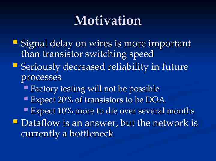
Motivation Signal delay on wires is more important than transistor switching speed Seriously decreased reliability in future processes Factory testing will not be possible Expect 20% of transistors to be DOA Expect 10% more to die over several months Dataflow is an answer, but the network is currently a bottleneck
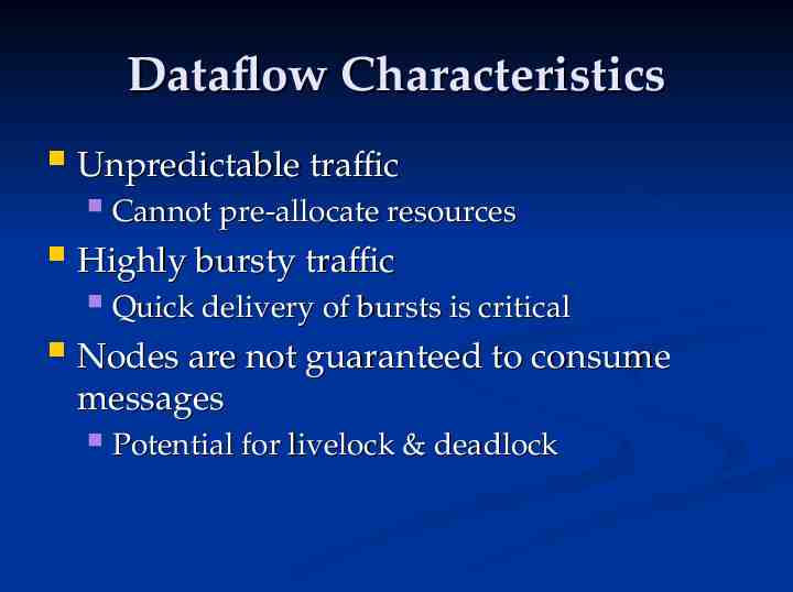
Dataflow Characteristics Unpredictable traffic Highly bursty traffic Cannot pre-allocate resources Quick delivery of bursts is critical Nodes are not guaranteed to consume messages Potential for livelock & deadlock
Overview Motivation & Design Constraints Network design Performance Adaptive Routing Conclusion
Network Requirements High-Performance during bursts Area efficient Guarantee message delivery Deadlock & Livelock free Fault Tolerant Regular 2-D physical structure
Topology On-chip - must be implementable in 2-D Regular tiled structure suggests: Grid Torus Hypercube Fat Tree Hypercube is difficult to route, scale Fat Tree has a single point of failure
Routing Static routing does not provide essential fault tolerance Use a modified Virtual Channel algorithm VC guarantees deadlock free if nodes consume messages Dynamically adaptive to handle transient faults & congestion Initial studies used static routing
Flow Control Resource reservation not possible Long-latency wires prohibit handshakes Send messages assuming accept Buffer just enough to allow receiver to send reject signal on subsequent clock cycle
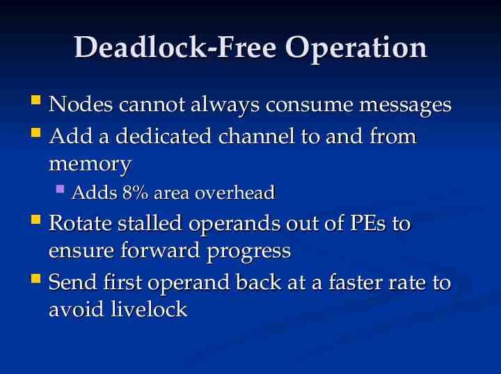
Deadlock-Free Operation Nodes cannot always consume messages Add a dedicated channel to and from memory Adds 8% area overhead Rotate stalled operands out of PEs to ensure forward progress Send first operand back at a faster rate to avoid livelock
Overview Motivation & Design Constraints Network design Performance Adaptive Routing Conclusion
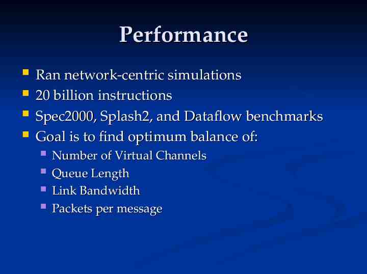
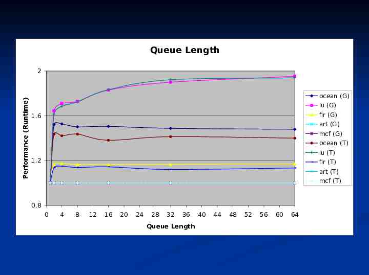
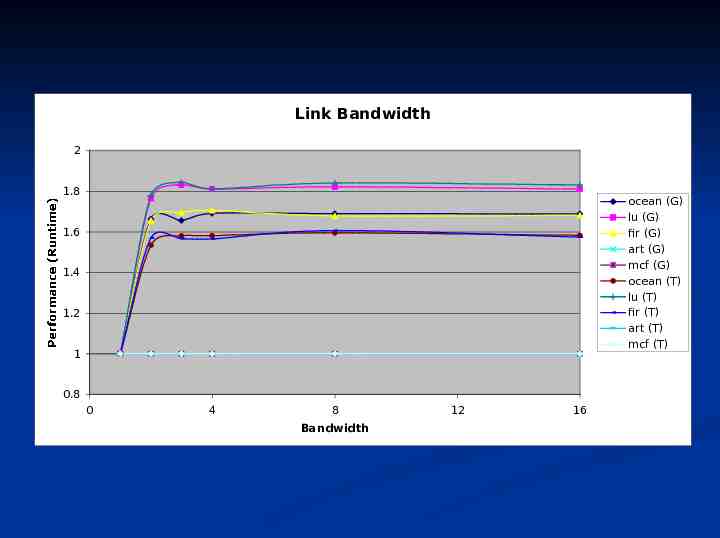
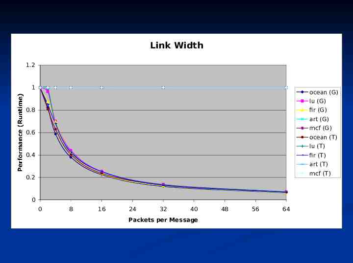
Performance Ran network-centric simulations 20 billion instructions Spec2000, Splash2, and Dataflow benchmarks Goal is to find optimum balance of: Number of Virtual Channels Queue Length Link Bandwidth Packets per message
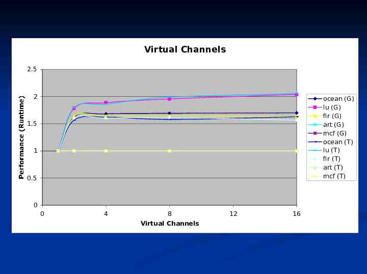
Virtual Channels 2.5 2 ocean (G) lu (G) fir (G) art (G) mcf (G) ocean (T) lu (T) fir (T) art (T) mcf (T) 1.5 1 Performance (Runtime) 0.5 0 0 4 8 Virtual Channels 12 16
Queue Length 2 ocean (G) lu (G) fir (G) 1.6 art (G) mcf (G) ocean (T) lu (T) 1.2 fir (T) art (T) Performance (Runtime) mcf (T) 0.8 0 4 8 12 16 20 24 28 32 36 Queue Length 40 44 48 52 56 60 64
Link Bandwidth 2 1.8 ocean (G) lu (G) fir (G) art (G) mcf (G) ocean (T) lu (T) fir (T) art (T) mcf (T) 1.6 1.4 1.2 Performance (Runtime) 1 0.8 0 4 8 Bandwidth 12 16
Link Width 1.2 1 ocean (G) lu (G) 0.8 fir (G) art (G) mcf (G) 0.6 ocean (T) lu (T) 0.4 fir (T) art (T) Performance (Runtime) 0.2 mcf (T) 0 0 8 16 24 32 40 Packets per Message 48 56 64
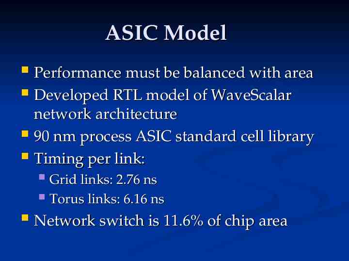
ASIC Model Performance must be balanced with area Developed RTL model of WaveScalar network architecture 90 nm process ASIC standard cell library Timing per link: Grid links: 2.76 ns Torus links: 6.16 ns Network switch is 11.6% of chip area
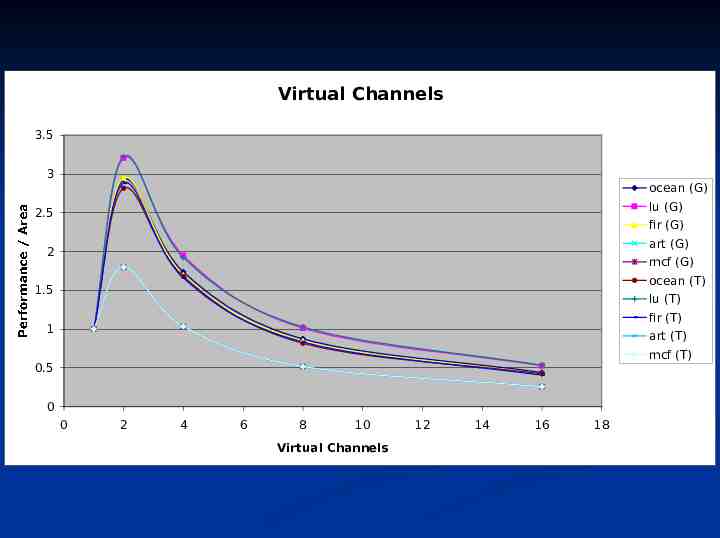
Virtual Channels 3.5 3 ocean (G) lu (G) 2.5 fir (G) art (G) 2 mcf (G) ocean (T) 1.5 lu (T) fir (T) 1 Performance / Area art (T) mcf (T) 0.5 0 0 2 4 6 8 10 Virtual Channels 12 14 16 18
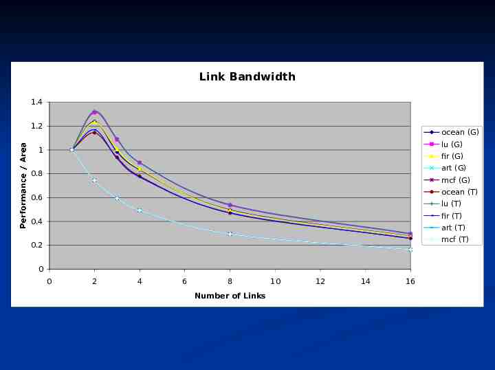
Link Bandwidth 1.4 1.2 ocean (G) lu (G) 1 fir (G) art (G) 0.8 mcf (G) ocean (T) 0.6 lu (T) fir (T) 0.4 Performance / Area art (T) mcf (T) 0.2 0 0 2 4 6 8 Number of Links 10 12 14 16
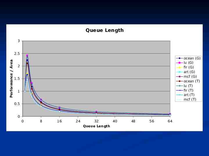
Queue Length 3 2.5 ocean (G) lu (G) fir (G) art (G) mcf (G) ocean (T) lu (T) fir (T) art (T) mcf (T) 2 1.5 1 Performance / Area 0.5 0 0 8 16 24 32 Queue Length 40 48 56 64
Overview Motivation & Design Constraints Network design Performance Adaptive Routing Conclusion
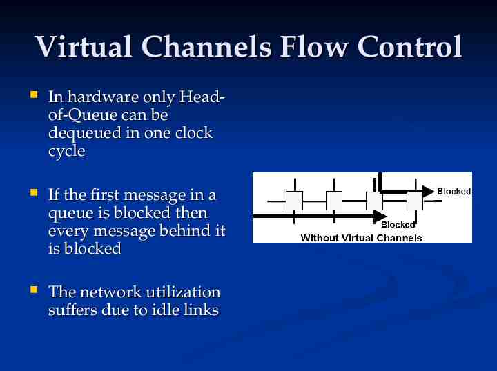
Virtual Channels Flow Control In hardware only Headof-Queue can be dequeued in one clock cycle If the first message in a queue is blocked then every message behind it is blocked The network utilization suffers due to idle links
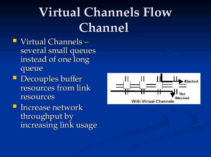
Virtual Channels Flow Channel Virtual Channels – several small queues instead of one long queue Decouples buffer resources from link resources Increase network throughput by increasing link usage
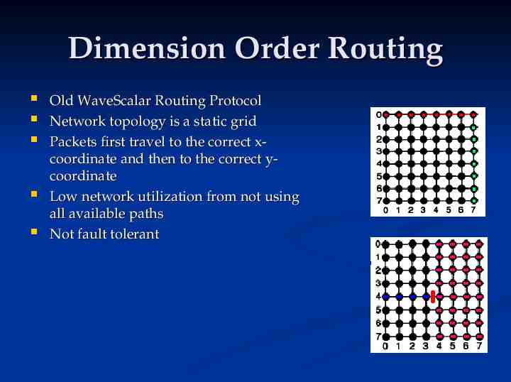
Dimension Order Routing Old WaveScalar Routing Protocol Network topology is a static grid Packets first travel to the correct xcoordinate and then to the correct ycoordinate Low network utilization from not using all available paths Not fault tolerant
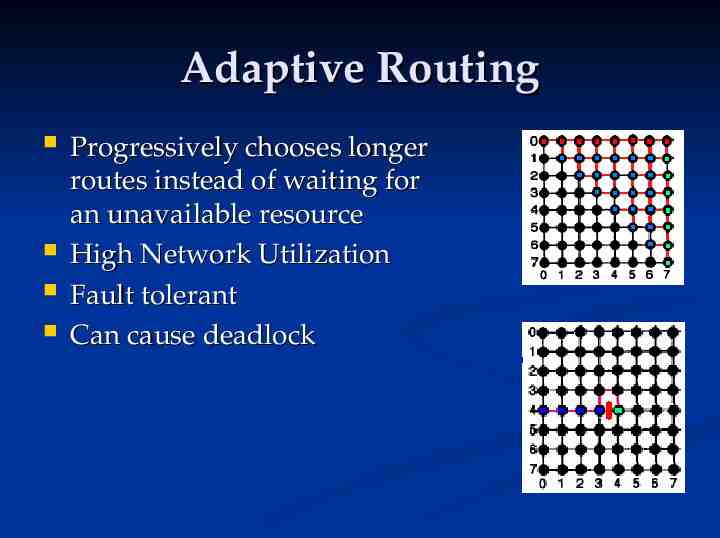
Adaptive Routing Progressively chooses longer routes instead of waiting for an unavailable resource High Network Utilization Fault tolerant Can cause deadlock
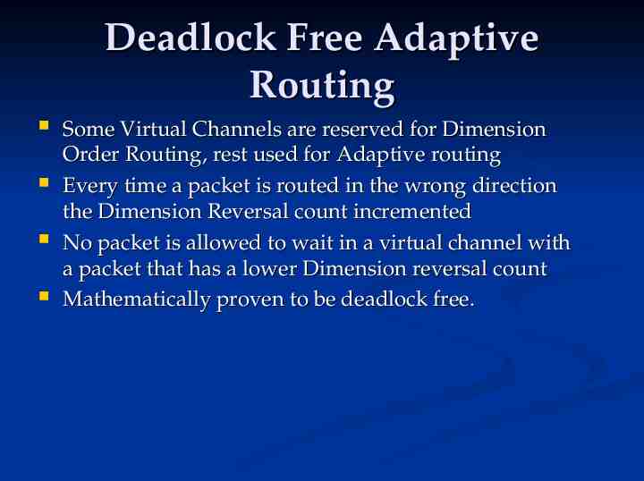
Deadlock Free Adaptive Routing Some Virtual Channels are reserved for Dimension Order Routing, rest used for Adaptive routing Every time a packet is routed in the wrong direction the Dimension Reversal count incremented No packet is allowed to wait in a virtual channel with a packet that has a lower Dimension reversal count Mathematically proven to be deadlock free.
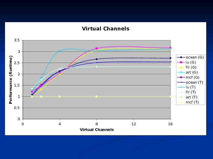
Virtual Channels 3.5 3 ocean (G) lu (G) fir (G) art (G) mcf (G) ocean (T) lu (T) fir (T) art (T) mcf (T) 2.5 2 1.5 1 Performance (Runtime) 0.5 0 0 4 8 Virtual Channels 12 16
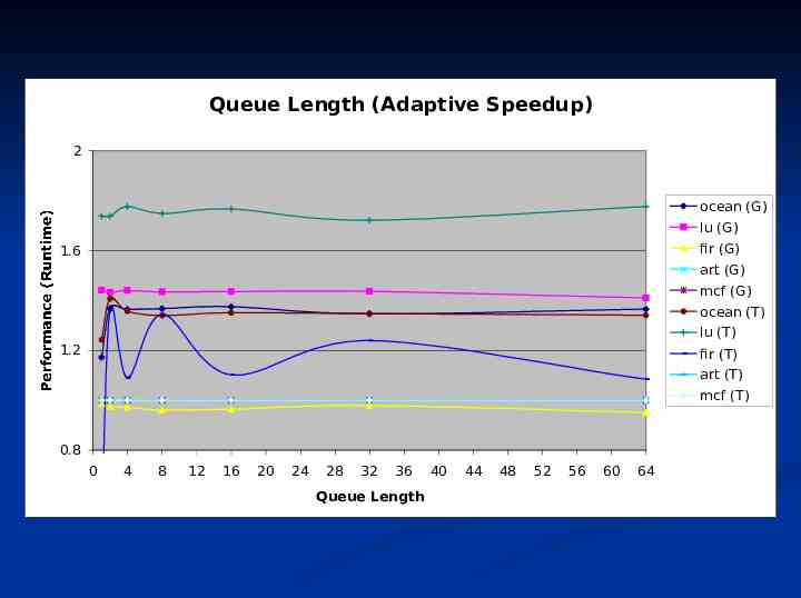
Queue Length (Adaptive Speedup) 2 ocean (G) lu (G) fir (G) 1.6 art (G) mcf (G) ocean (T) lu (T) 1.2 fir (T) art (T) Performance (Runtime) mcf (T) 0.8 0 4 8 12 16 20 24 28 32 36 Queue Length 40 44 48 52 56 60 64
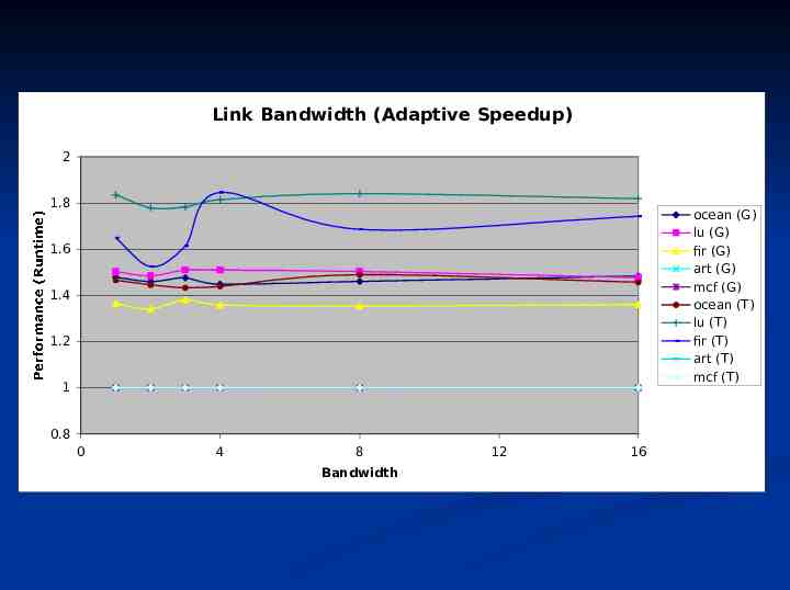
Link Bandwidth (Adaptive Speedup) 2 1.8 ocean (G) lu (G) fir (G) art (G) mcf (G) ocean (T) lu (T) fir (T) art (T) mcf (T) 1.6 1.4 1.2 Performance (Runtime) 1 0.8 0 4 8 Bandwidth 12 16
Conclusion Best performance per area with: 2 Virtual Channels 2 Links 2-4 entries per queue Torus Topology Adaptive Routing Dataflow chip networks can be highperformance at reasonable area