EE345S Real-Time Digital Signal Processing Lab Spring 2006
30 Slides436.00 KB
EE345S Real-Time Digital Signal Processing Lab Spring 2006 Matched Filtering and Digital Pulse Amplitude Modulation (PAM) Slides by Prof. Brian L. Evans and Dr. Serene Banerjee Dept. of Electrical and Computer Engineering The University of Texas at Austin Lecture 13
Outline PAM Matched Filtering PAM System Transmit Bits Intersymbol Interference (ISI) – Bit error probability for binary signals – Bit error probability for M-ary (multilevel) signals Eye Diagram 13 - 2
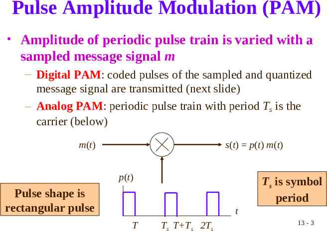
Pulse Amplitude Modulation (PAM) Amplitude of periodic pulse train is varied with a sampled message signal m – Digital PAM: coded pulses of the sampled and quantized message signal are transmitted (next slide) – Analog PAM: periodic pulse train with period Ts is the carrier (below) m(t) s(t) p(t) m(t) p(t) Ts is symbol period Pulse shape is rectangular pulse t T Ts T Ts 2Ts 13 - 3
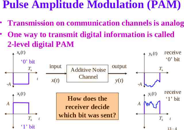
Pulse Amplitude Modulation (PAM) Transmission on communication channels is analog One way to transmit digital information is called 2-level digital PAM x0 (t ) receive ‘0’ bit y0 (t ) ‘0’ bit input b t x(t) -A x1 (t ) A b ‘1’ bit t Additive Noise Channel output y(t) How does the receiver decide which bit was sent? b -A receive ‘1’ bit y1 (t ) A b t 13 - 4
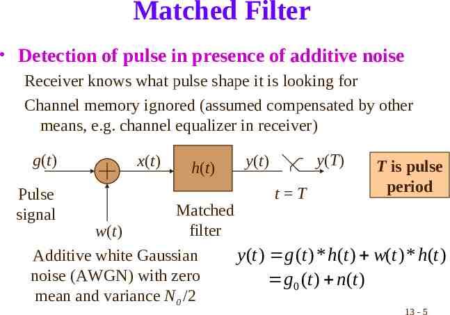
Matched Filter Detection of pulse in presence of additive noise Receiver knows what pulse shape it is looking for Channel memory ignored (assumed compensated by other means, e.g. channel equalizer in receiver) g(t) Pulse signal x(t) h(t) Matched filter w(t) Additive white Gaussian noise (AWGN) with zero mean and variance N0 /2 y(T) y(t) t T T is pulse period y (t ) g (t ) * h(t ) w(t ) * h(t ) g 0 (t ) n(t ) 13 - 5
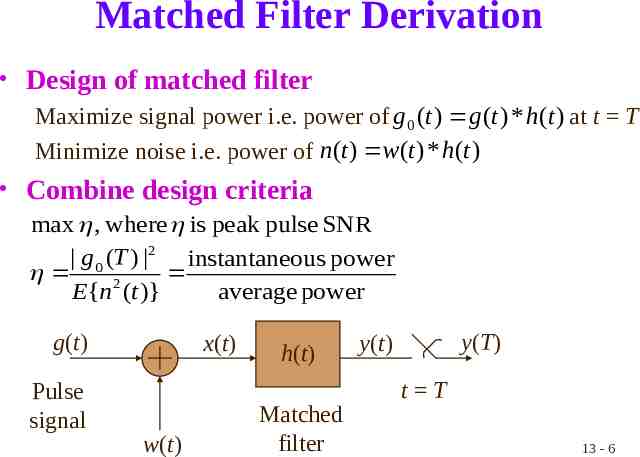
Matched Filter Derivation Design of matched filter Maximize signal power i.e. power of g 0 (t ) g (t ) * h(t ) at t T Minimize noise i.e. power of n(t ) w(t ) * h(t ) Combine design criteria max , where is peak pulse SNR g 0 (T ) 2 instantaneous power 2 E{n (t )} average power g(t) Pulse signal x(t) w(t) h(t) Matched filter y(T) y(t) t T 13 - 6
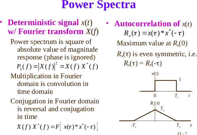
Power Spectra Deterministic signal x(t) Autocorrelation of x(t) w/ Fourier transform X(f) Rx ( ) x( ) * x* ( ) Power spectrum is square of Maximum value at Rx(0) absolute value of magnitude Rx( ) is even symmetric, i.e. response (phase is ignored) 2 Rx( ) Rx(- ) P ( f ) X ( f ) X ( f ) X * ( f ) x x(t) Multiplication in Fourier domain is convolution in time domain Conjugation in Fourier domain is reversal and conjugation in time X ( f ) X * ( f ) F x( ) * x* ( ) 1 0 Rx( ) -Ts Ts t Ts Ts 13 - 7
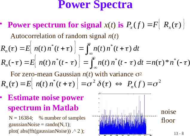
Power Spectra Power spectrum for signal x(t) is Px ( f ) F Rx ( ) Autocorrelation of random signal n(t) Rn ( ) E n(t ) n (t ) n(t ) n* (t ) dt * Rn ( ) E n(t ) n* (t ) n(t ) n* (t ) dt n( ) * n* ( ) For zero-mean Gaussian n(t) with variance 2 Rn ( ) E n(t ) n* (t ) 2 ( ) Pn ( f ) 2 Estimate noise power spectrum in Matlab N 16384; % number of samples gaussianNoise randn(N,1); plot( abs(fft(gaussianNoise)) . 2 ); noise floor 13 - 8
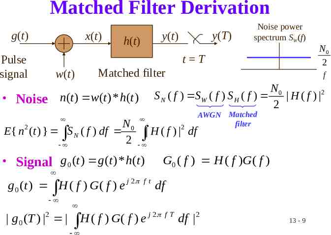
Matched Filter Derivation g(t) Pulse signal x(t) y(T) y(t) h(t) Noise power spectrum SW(f) t T w(t) Matched filter E{ n 2 (t ) } S N ( f ) df N0 2 f S N ( f ) SW ( f ) S H ( f ) Noise n(t ) w(t ) * h(t ) 2 H ( f ) df AWGN Matched filter N0 H ( f ) 2 2 G0 ( f ) H ( f )G ( f ) Signal g 0 (t ) g (t ) * h(t ) g 0 (t ) H ( f ) G ( f ) e j 2 g 0 (T ) 2 f t df j 2 H ( f ) G ( f ) e fT N0 2 df 2 13 - 9
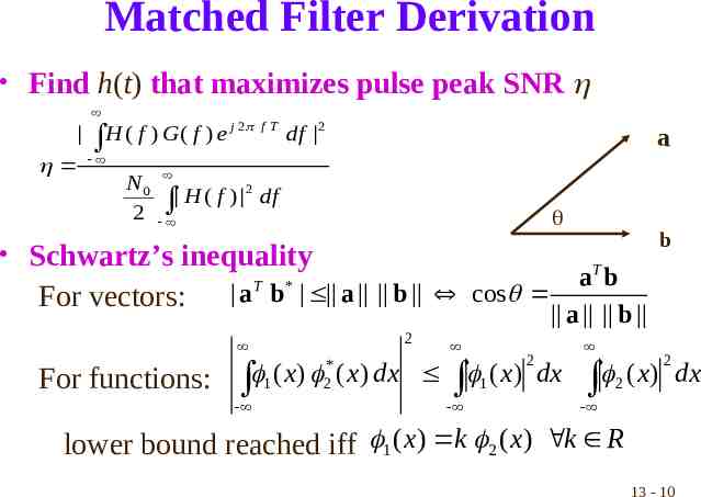
Matched Filter Derivation Find h(t) that maximizes pulse peak SNR H ( f ) G ( f ) e j 2 f T df 2 a N0 2 2 H ( f ) df b Schwartz’s inequality For vectors: T a b T * a b a b cos a b 2 For functions: ( x) 1 - * 2 2 ( x) dx 1 ( x) dx - ( x) 2 2 - lower bound reached iff 1 ( x) k 2 ( x) k R 13 - 10 dx
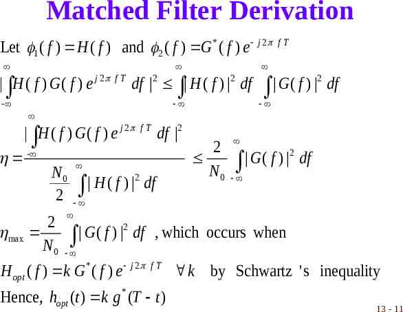
Matched Filter Derivation Let 1 ( f ) H ( f ) and 2 ( f ) G * ( f ) e j 2 f T H ( f ) G ( f ) e j 2 f T df 2 H ( f ) 2 df - 2 G ( f ) df H ( f ) G ( f ) e j 2 f T df 2 2 - N0 N0 2 H ( f ) df 2 2 G ( f ) df 2 2 max G ( f ) df , which occurs when N0 H opt ( f ) k G * ( f ) e j 2 f T k by Schwartz ' s inequality Hence, hopt (t ) k g * (T t ) 13 - 11
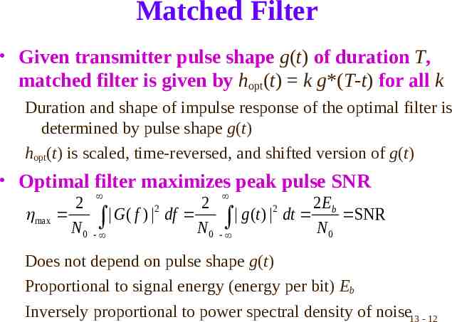
Matched Filter Given transmitter pulse shape g(t) of duration T, matched filter is given by hopt(t) k g*(T-t) for all k Duration and shape of impulse response of the optimal filter is determined by pulse shape g(t) hopt(t) is scaled, time-reversed, and shifted version of g(t) Optimal filter maximizes peak pulse SNR 2 2 2 Eb 2 2 max G ( f ) df g (t ) dt SNR N0 N0 N0 Does not depend on pulse shape g(t) Proportional to signal energy (energy per bit) Eb Inversely proportional to power spectral density of noise13 - 12
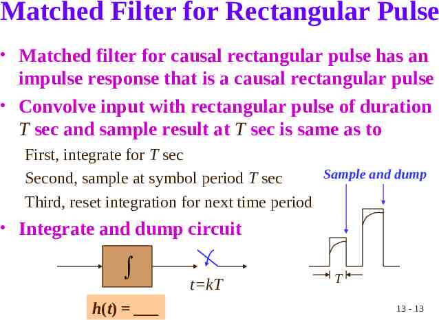
Matched Filter for Rectangular Pulse Matched filter for causal rectangular pulse has an impulse response that is a causal rectangular pulse Convolve input with rectangular pulse of duration T sec and sample result at T sec is same as to First, integrate for T sec Sample and dump Second, sample at symbol period T sec Third, reset integration for next time period Integrate and dump circuit h(t) t kT T 13 - 13
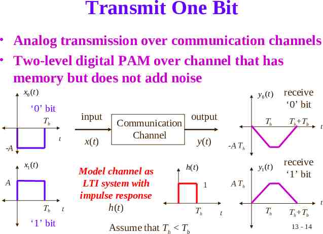
Transmit One Bit Analog transmission over communication channels Two-level digital PAM over channel that has memory but does not add noise x0 (t ) ‘0’ bit input b t x(t) -A x1 (t ) A b ‘1’ bit t output Communication Channel Model channel as LTI system with impulse response h(t) y(t) receive ‘0’ bit h h b t -A Th y1 (t ) h(t ) Assume that Th Tb y0 (t ) A Th 1 receive ‘1’ bit t h t h h b 13 - 14
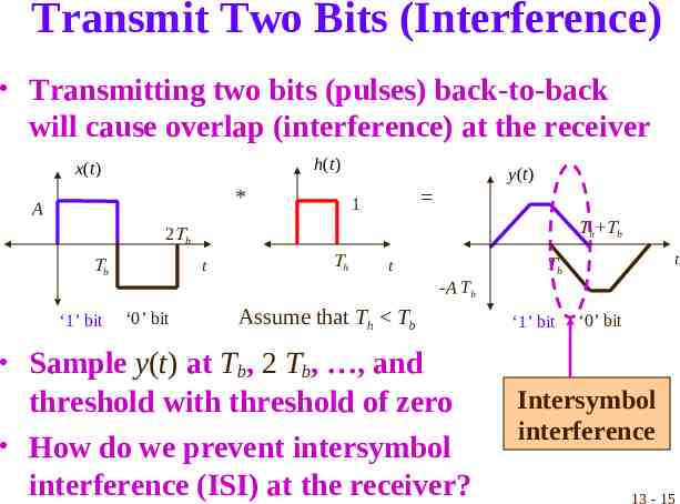
Transmit Two Bits (Interference) Transmitting two bits (pulses) back-to-back will cause overlap (interference) at the receiver h(t ) x(t ) * A y (t ) 1 h b b t b ‘1’ bit h t t b -A Th ‘0’ bit Assume that Th Tb ‘1’ bit ‘0’ bit Sample y(t) at Tb, 2 Tb, , and threshold with threshold of zero How do we prevent intersymbol interference (ISI) at the receiver? Intersymbol interference 13 - 15
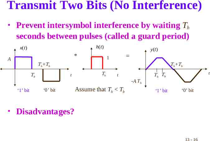
Transmit Two Bits (No Interference) Prevent intersymbol interference by waiting Th seconds between pulses (called a guard period) h(t ) x(t ) * A y (t ) 1 h b t b ‘1’ bit h b h t -A Th ‘0’ bit Assume that Th Tb t h b ‘1’ bit ‘0’ bit Disadvantages? 13 - 16
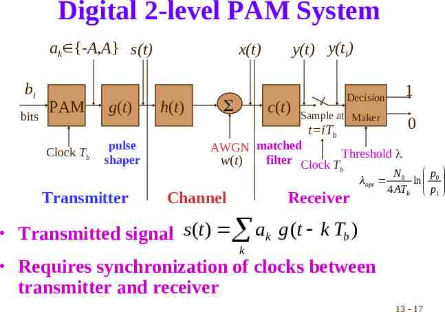
Digital 2-level PAM System ak {-A,A} s(t) bi bits PAM Clock Tb g(t) pulse shaper y(t) y(ti) x(t) h(t) c(t) Sample at Maker t iTb 0 AWGN matched Threshold filter Clock T w(t) b opt Transmitter 1 Decision Channel Receiver Transmitted signal s (t ) a k p N0 ln 0 4 ATb p1 g (t k Tb ) k Requires synchronization of clocks between transmitter and receiver 13 - 17
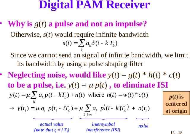
Digital PAM Receiver Why is g(t) a pulse and not an impulse? Otherwise, s(t) would require infinite bandwidth s (t ) ak (t k Tb ) k Since we cannot send an signal of infinite bandwidth, we limit its bandwidth by using a pulse shaping filter Neglecting noise, would like y(t) g(t) * h(t) * c(t) to be a pulse, i.e. y(t) p(t) , to eliminate ISI y (t ) ak p (t kTb ) n(t ) where n(t ) w(t ) * c(t ) k y (ti ) ai p (ti iTb ) ak p (i k )Tb n(ti ) k , k i actual value (note that ti i Tb) intersymbol interference (ISI) p(t) is centered at origin noise 13 - 18
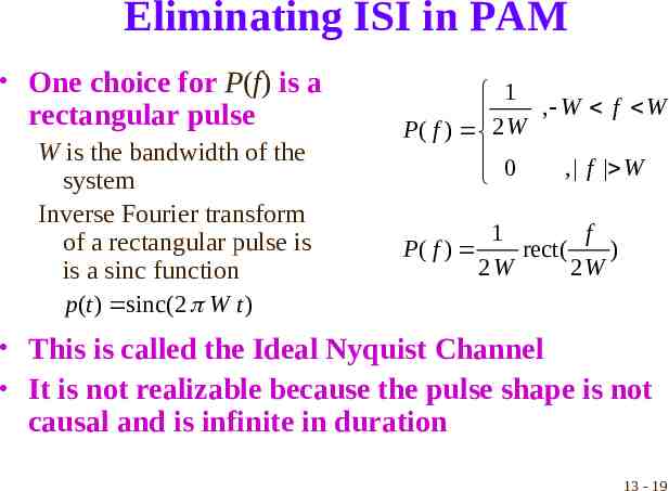
Eliminating ISI in PAM One choice for P(f) is a rectangular pulse W is the bandwidth of the system Inverse Fourier transform of a rectangular pulse is is a sinc function p (t ) sinc(2 W t ) 1 2 W , W f W P( f ) 0 , f W 1 f P( f ) rect ( ) 2W 2W This is called the Ideal Nyquist Channel It is not realizable because the pulse shape is not causal and is infinite in duration 13 - 19
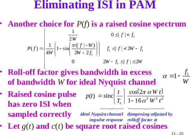
Eliminating ISI in PAM Another choice for P(f) is a raised cosine spectrum 1 P( f ) 4W 1 0 f f1 2W 1 sin ( f W ) f1 f 2W f1 2W 2 f 1 0 2W f1 f 2W Roll-off factor gives bandwidth in excess 1 of bandwidth W for ideal Nyquist channel Raised cosine pulse p(t ) sinc t cos 2 2 W2 t 2 T 1 16 W t s has zero ISI when sampled correctly ideal Nyquist channel dampening adjusted by impulse response rolloff factor Let g(t) and c(t) be square root raised cosines f1 W 13 - 20
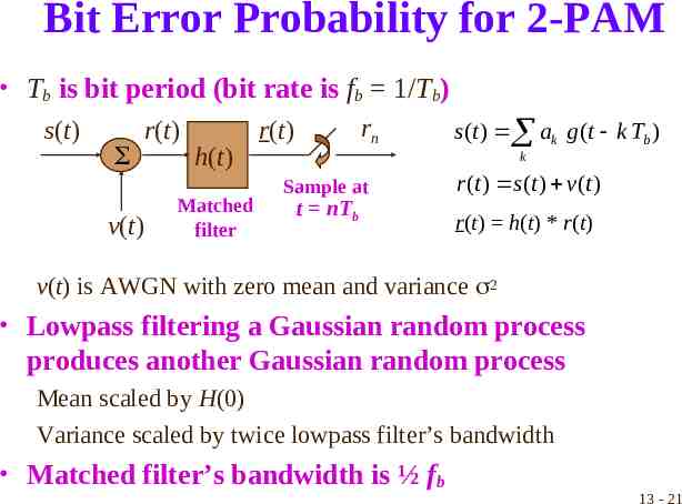
Bit Error Probability for 2-PAM Tb is bit period (bit rate is fb 1/Tb) s(t) r(t) v(t) h(t) Matched filter rn r(t) s (t ) ak g (t k Tb ) k Sample at t nTb r (t ) s (t ) v(t ) r(t) h(t) * r(t) v(t) is AWGN with zero mean and variance 2 Lowpass filtering a Gaussian random process produces another Gaussian random process Mean scaled by H(0) Variance scaled by twice lowpass filter’s bandwidth Matched filter’s bandwidth is ½ fb 13 - 21
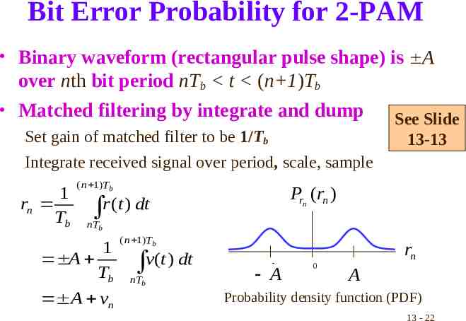
Bit Error Probability for 2-PAM Binary waveform (rectangular pulse shape) is A over nth bit period nTb t (n 1)Tb Matched filtering by integrate and dump Set gain of matched filter to be 1/Tb Integrate received signal over period, scale, sample 1 rn Tb ( n 1)Tb See Slide 13-13 Prn (rn ) r (t ) dt nTb 1 A Tb A vn ( n 1)Tb v(t ) dt nTb - A 0 rn A Probability density function (PDF) 13 - 22
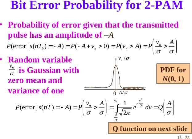
Bit Error Probability for 2-PAM Probability of error given that the transmitted pulse has an amplitude of –A vn A P(error s (nTb ) A) P ( A vn 0) P (vn A) P Random variable vn / vn is Gaussian with zero mean and variance of one PDF for N(0, 1) 0 A / 1 vn A P(error s(nT ) A) P e A 2 v2 2 A dv Q Q function on next slide 13 - 23
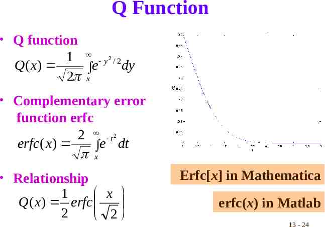
Q Function Q function 1 y2 / 2 Q( x) dy e 2 x Complementary error function erfc 2 t2 erfc ( x) e dt x Relationship 1 x Q( x) erfc 2 2 Erfc[x] in Mathematica erfc(x) in Matlab 13 - 24
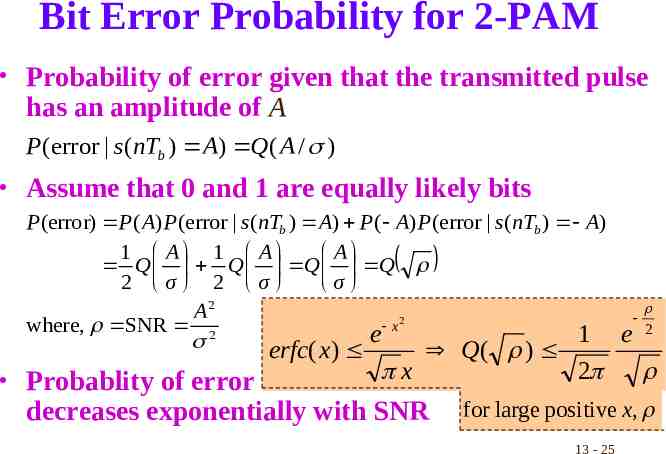
Bit Error Probability for 2-PAM Probability of error given that the transmitted pulse has an amplitude of A P (error s (nTb ) A) Q( A / ) Assume that 0 and 1 are equally likely bits P(error) P( A) P(error s (nTb ) A) P( A) P (error s (nTb ) A) 1 A 1 A A Q Q Q Q 2 σ 2 σ σ A2 2 x where, SNR 2 2 e 1 e erfc( x) Q( ) Probablity of error x decreases exponentially with SNR 2 for large positive x, 13 - 25
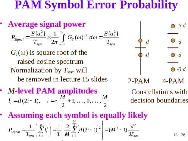
PAM Symbol Error Probability Average signal power PSignal E{an2 } 1 Tsym 2 3d E{an2 } GT ( ) d Tsym 2 GT( ) is square root of the raised cosine spectrum Normalization by Tsym will be removed in lecture 15 slides M-level PAM amplitudes li d (2i 1), i M M 1, . . . , 0, . . . , 2 2 d d -d -d -3 d 2-PAM 4-PAM Constellations with decision boundaries Assuming each symbol is equally likely PSignal 1 M 2 1 2 li Tsym i 1 T M M 2 d2 2 2 d (2i 1) ( M 1) 3Tsym i 1 13 - 26
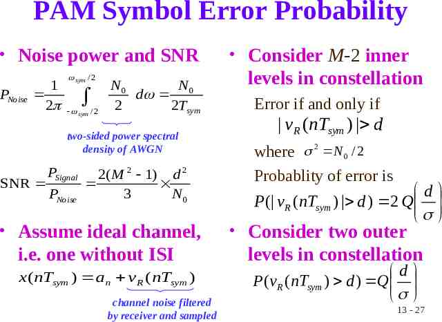
PAM Symbol Error Probability Noise power and SNR PNoise 1 2 sym / 2 sym /2 N0 N d 0 2 2Tsym two-sided power spectral density of AWGN SNR PSignal PNoise 2( M 2 1) d 2 3 N0 Assume ideal channel, i.e. one without ISI x (nTsym ) an v R ( nTsym ) channel noise filtered by receiver and sampled Consider M-2 inner levels in constellation Error if and only if vR (nTsym ) d where 2 N 0 / 2 Probablity of error is d P ( vR (nTsym ) d ) 2 Q Consider two outer levels in constellation d P(vR (nTsym ) d ) Q 13 - 27
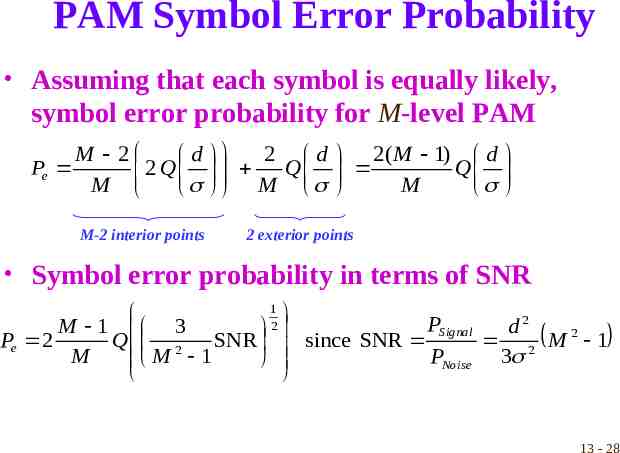
PAM Symbol Error Probability Assuming that each symbol is equally likely, symbol error probability for M-level PAM Pe M 2 d 2 Q M M-2 interior points 2 d 2( M 1) d Q Q M M 2 exterior points Symbol error probability in terms of SNR 1 PSignal M 1 3 d2 2 Pe 2 Q 2 SNR since SNR 2 M2 1 M PNoise 3 M 1 13 - 28
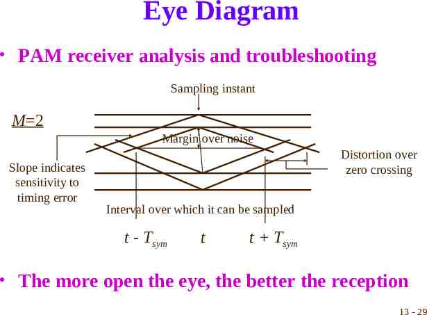
Eye Diagram PAM receiver analysis and troubleshooting Sampling instant M 2 Margin over noise Slope indicates sensitivity to timing error Distortion over zero crossing Interval over which it can be sampled t - Tsym t t Tsym The more open the eye, the better the reception 13 - 29
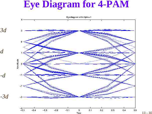
Eye Diagram for 4-PAM 3d d -d -3d 13 - 30