Chapter 7 – Design and Implementation part 1 Credits to
56 Slides854.50 KB
Chapter 7 – Design and Implementation part 1 Credits to Sommerville book, Dr. Chays and Russell C. Bjork of Gordon College in MA Chapter 7 Design and implementation 1
Topics covered Object-oriented design using the UML Design patterns Implementation issues Open source development Chapter 7 Design and implementation 2
Design and implementation Design and Code and Unit Test Software design and implementation activities are invariably inter-leaved. Design: process of identifying software components and their relationships at a detailed level Implementation: process of realizing the design as a program. Build or Buy – COTS Design involves understanding COTS Configuration plus Changes from given COTS Chapter 7 Design and implementation 3
An object-oriented design process Common activities in these processes include: Define the context and modes of use of the system; Design the system architecture; Identify the principal system objects; Develop design models; Specify object interfaces. Process illustrated here using a design for a wilderness weather station. Chapter 7 Design and implementation 4
System context and interactions (part of req) Goals Understanding the relationships between the software that is being designed and its external environment Understanding of the context also lets you establish the boundaries of the system. Models: A system context model is a structural model that demonstrates the other systems in the environment of the system being developed. An interaction model is a dynamic model that shows how the system interacts with its environment as it is used. Chapter 7 Design and implementation 5
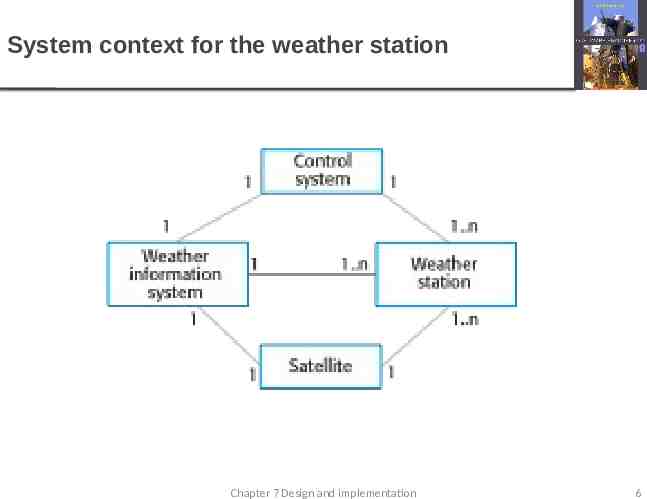
System context for the weather station Chapter 7 Design and implementation 6
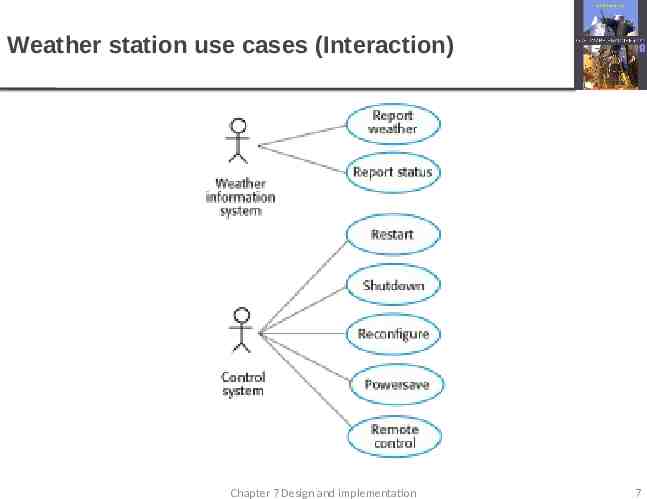
Weather station use cases (Interaction) Chapter 7 Design and implementation 7
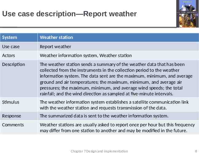
Use case description—Report weather System Weather station Use case Report weather Actors Weather information system, Weather station Description The weather station sends a summary of the weather data that has been collected from the instruments in the collection period to the weather information system. The data sent are the maximum, minimum, and average ground and air temperatures; the maximum, minimum, and average air pressures; the maximum, minimum, and average wind speeds; the total rainfall; and the wind direction as sampled at five-minute intervals. Stimulus The weather information system establishes a satellite communication link with the weather station and requests transmission of the data. Response The summarized data is sent to the weather information system. Comments Weather stations are usually asked to report once per hour but this frequency may differ from one station to another and may be modified in the future. Chapter 7 Design and implementation 8
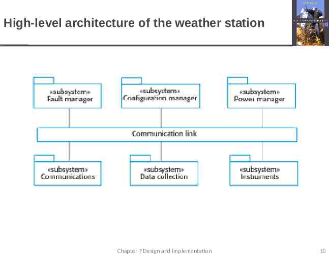
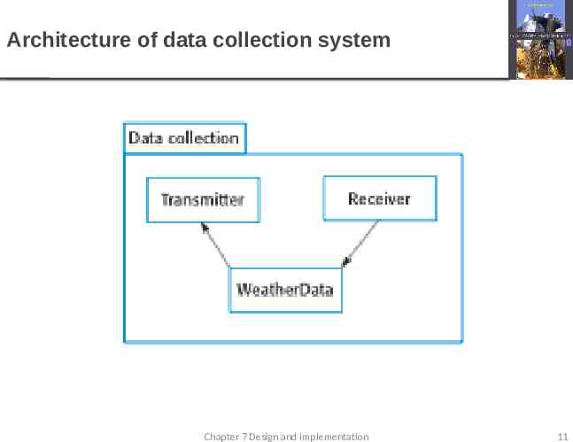
Architectural design – part of req Once interactions between the system and its environment have been understood, you use this information for designing the system architecture. You identify the major components that make up the system and their interactions, and then may organize the components using an architectural pattern such as a layered or client-server model. The weather station is composed of independent subsystems that communicate by broadcasting messages on a common infrastructure. Chapter 7 Design and implementation 9
High-level architecture of the weather station Chapter 7 Design and implementation 10
Architecture of data collection system Chapter 7 Design and implementation 11
Object class identification – Design! Identifying object classes is often a difficult part of object oriented design. There is no 'magic formula' for object identification. It relies on the skill, experience and domain knowledge of system designers. Object identification is an iterative process. You are unlikely to get it right first time. Chapter 7 Design and implementation 12
Approaches to identification Use a grammatical approach based on a natural language description of the system (used in Hood OOD method). Base the identification on tangible things in the application domain. Use a behavioural approach and identify objects based on what participates in what behaviour. Use a scenario-based analysis. The objects, attributes and methods in each scenario are identified. Chapter 7 Design and implementation 13
Weather station description A weather station is a package of software controlled instruments which collects data, performs some data processing and transmits this data for further processing. The instruments include air and ground thermometers, an anemometer, a wind vane, a barometer and a rain gauge. Data is collected periodically. When a command is issued to transmit the weather data, the weather station processes and summarises the collected data. The summarised data is transmitted to the mapping computer when a request is received. Chapter 7 Design and implementation 14
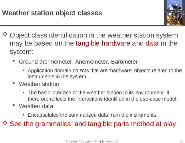
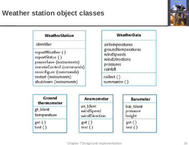
Weather station object classes Object class identification in the weather station system may be based on the tangible hardware and data in the system: Ground thermometer, Anemometer, Barometer Application domain objects that are ‘hardware’ objects related to the instruments in the system. Weather station The basic interface of the weather station to its environment. It therefore reflects the interactions identified in the use-case model. Weather data Encapsulates the summarized data from the instruments. See the grammatical and tangible parts method at play Chapter 7 Design and implementation 15
Weather station object classes Chapter 7 Design and implementation 16
Analyze by Types of analysis objects Entity objects Persistent information used by the system Does not include “helper” objects, which are usually transient Control objects Encapsulated functionality of various parts of the system Boundary objects Interaction between the actors and the system Normally, the analysis objects are closely tied to use cases
Example: use case diagram for the Scheduler, version 0.0.3
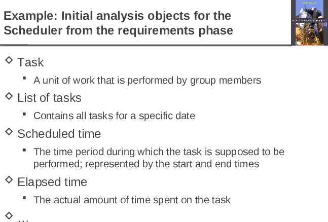
Example: Initial analysis objects for the Scheduler from the requirements phase Task A unit of work that is performed by group members List of tasks Contains all tasks for a specific date Scheduled time The time period during which the task is supposed to be performed; represented by the start and end times Elapsed time The actual amount of time spent on the task
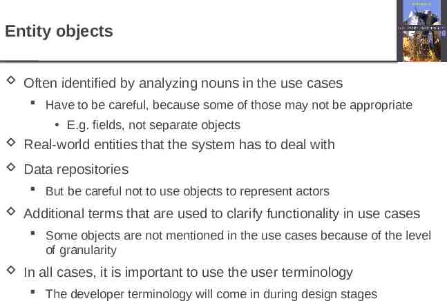
Entity objects Often identified by analyzing nouns in the use cases Have to be careful, because some of those may not be appropriate E.g. fields, not separate objects Real-world entities that the system has to deal with Data repositories But be careful not to use objects to represent actors Additional terms that are used to clarify functionality in use cases Some objects are not mentioned in the use cases because of the level of granularity In all cases, it is important to use the user terminology The developer terminology will come in during design stages
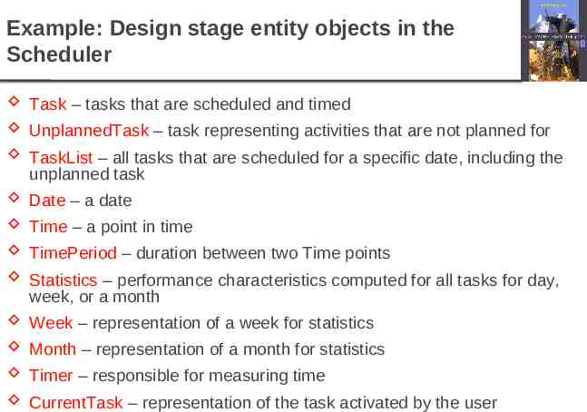
Example: Design stage entity objects in the Scheduler Task – tasks that are scheduled and timed UnplannedTask – task representing activities that are not planned for TaskList – all tasks that are scheduled for a specific date, including the unplanned task Date – a date Time – a point in time TimePeriod – duration between two Time points Statistics – performance characteristics computed for all tasks for day, week, or a month Week – representation of a week for statistics Month – representation of a month for statistics Timer – responsible for measuring time CurrentTask – representation of the task activated by the user
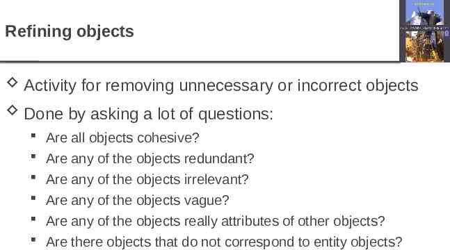
Refining objects Activity for removing unnecessary or incorrect objects Done by asking a lot of questions: Are all objects cohesive? Are any of the objects redundant? Are any of the objects irrelevant? Are any of the objects vague? Are any of the objects really attributes of other objects? Are there objects that do not correspond to entity objects?
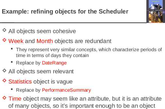
Example: refining objects for the Scheduler All objects seem cohesive Week and Month objects are redundant They represent very similar concepts, which characterize periods of time in terms of days they contain Replace by DateRange All objects seem relevant Statistics object is vague Replace by PerformanceSummary Time object may seem like an attribute, but it is an attribute of many objects, so it’s important enough to be an object
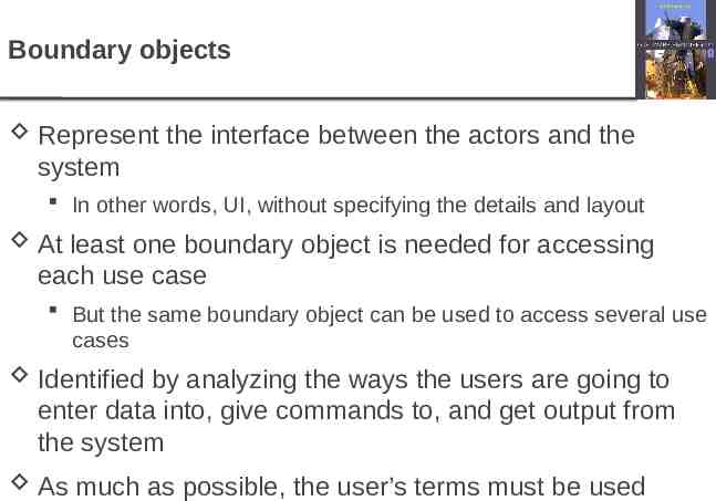
Boundary objects Represent the interface between the actors and the system In other words, UI, without specifying the details and layout At least one boundary object is needed for accessing each use case But the same boundary object can be used to access several use cases Identified by analyzing the ways the users are going to enter data into, give commands to, and get output from the system As much as possible, the user’s terms must be used
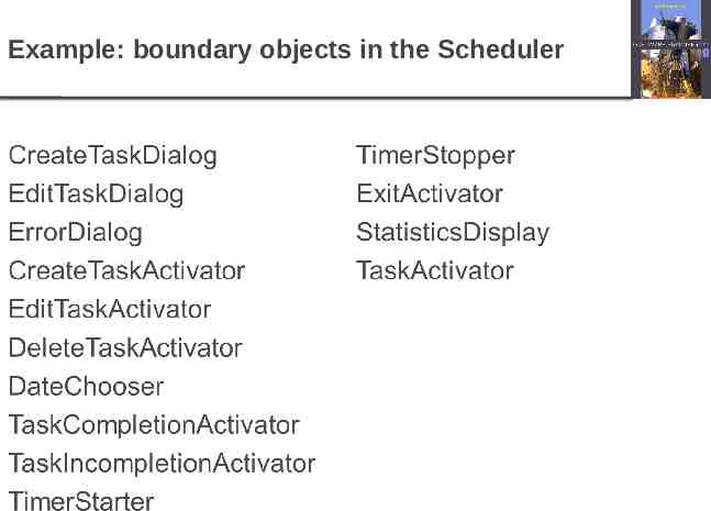
Example: boundary objects in the Scheduler
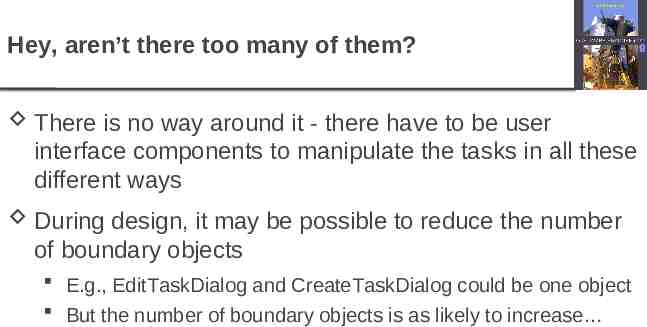
Hey, aren’t there too many of them? There is no way around it - there have to be user interface components to manipulate the tasks in all these different ways During design, it may be possible to reduce the number of boundary objects E.g., EditTaskDialog and CreateTaskDialog could be one object But the number of boundary objects is as likely to increase
Control objects That’s where the logic of the system resides Coordinate the other types of objects Often, a control object per use case Because a user case represents a specific kind of functionality, which needs to be controlled For complicated use cases, more than one control object may be needed One control object may control several simple related use cases
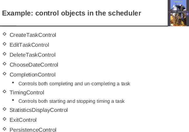
Example: control objects in the scheduler CreateTaskControl EditTaskControl DeleteTaskControl ChooseDateControl CompletionControl Controls both completing and un-completing a task TimingControl Controls both starting and stopping timing a task StatisticsDisplayControl ExitControl PersistenceControl
Hey, aren’t there too many of them? Yes and no Yes: some of these control objects are very closely related and so can be fused into one E.g., CreateTaskControl, EditTaskControl, and DeleteTaskControl can be replaced by TaskControl object E.g., ExitControl doesn’t have to do much except for saving the task data, so its functionality could be rolled into PersistenceControl No: we are looking at the system from the user’s perspective Having different control objects for creating, editing, and deleting tasks makes these operations explicit in the analysis model
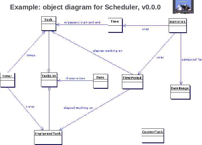
Example: object diagram for Scheduler, v0.0.0
Types of design goals Performance Response time, memory requirements, etc. Dependability Robustness, availability, fault tolerance, safety Security Cost factors Development, deployment, upgrade, maintenance, administration costs Maintenance factors Extensibility, modifiability, portability, understandability End user factors Utility and usability
Are design goals dependent on each other? There are many trade-offs Execution time can be reduced for the cost of higher memory usage (and vice versa) Improving usability of the system increases development cost More careful development increases development cost but decreases maintenance cost There are many positive co-dependencies Improved usability and portability reduce deployment costs Improved security reduces maintenance costs
CRC Cards Ward Cunningham and Kent Beck to help teach OO, turning data oriented thinkers into OO thinkers http://c2.com/doc/oopsla89/paper.html Extreme programmers are advocates of the CRC card Used as a tool for design, not something to be kept updated or published A good recent discussion: http://www.coderanch.com/t/98511/patterns/indentifyingclasses Chapter 7 Design and implementation 33
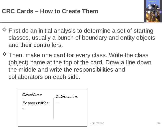
CRC Cards – How to Create Them First do an initial analysis to determine a set of starting classes, usually a bunch of boundary and entity objects and their controllers. Then, make one card for every class. Write the class (object) name at the top of the card. Draw a line down the middle and write the responsibilities and collaborators on each side. Chapter 7 Design and implementation 34
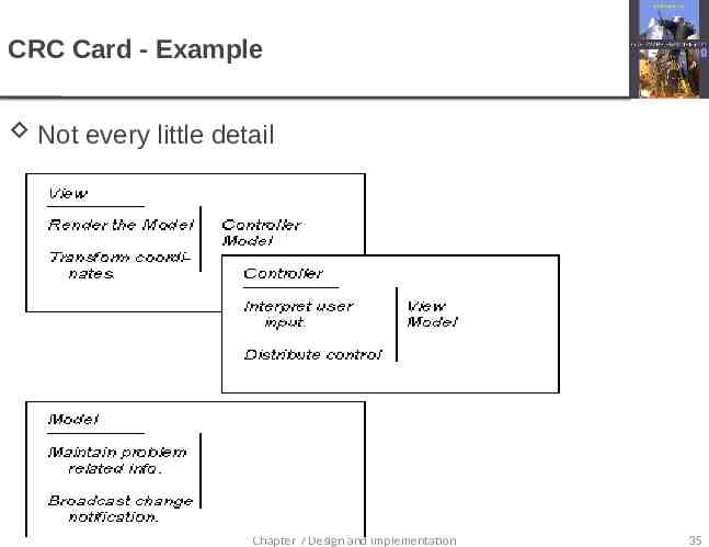
CRC Card - Example Not every little detail Chapter 7 Design and implementation 35
CRC Card – Use them to walk through After writing initial cards walk through scenarios and use cases A set of cards in front of you Hold up the cards as you talk about the situation Add cards or responsibilities as needed. Keep placing them back on the table in ways that make sense. Cards that are closely related may overlap Cards that oversee other objects should be on top Aggregation and inheritance should be reflected by having parts below the whole. This will probably come naturally. Just place the cards where they make the most sense to the team Chapter 7 Design and implementation 36
ATM Example Class exercise: What classes will you need to handle a typical ATM machine? The ATM will handle withdrawals, deposits, transfers and inquiries. Requirements statement: http://www.math-cs.gordon.edu/courses/cps211/ATMExample/R equirements.html First basic use case, then first pass analyze classes and finally create CRC cards and then class, state and sequence diagrams Chapter 7 Design and implementation 37
ATM Example – Use Cases We have done a few already, but let’s do one more quickly for practice. Everyone quickly write a use case on paper from the requirements page: http:// www.math-cs.gordon.edu/courses/cps211/ATMExample/Requirement s.html When you are done: See Bjork’s suggestion when you are done http://www.math-cs.gordon.edu/courses/cps211/ATMExample/UseCa ses.html Click on an action to see a worded use case Click on the related sequence diagram, especially transaction sequence diagram Click on withdrawal to see a collaboration diagram – just for info Chapter 7 Design and implementation 38
ATM Example – first pass analyze classes First, lets analyze classes, looking for entity, control and boundary objects AND considering grammatical, tangible and behavior concepts AND also looking at use cases Consider Requirements def: http:// www.math-cs.gordon.edu/courses/cps211/ATMExample/Requirements.html use cases: http://www.math-cs.gordon.edu/courses/cps211/ATMExample/UseCases.html Functional tests (we skipped these): http://www.math-cs.gordon.edu/courses/cps211/ATMExample/InitialFunctional Tests.html Don’t look at Bjork’s suggestions until we get past the CRC cards and writing our own class diagrams Chapter 7 Design and implementation 39
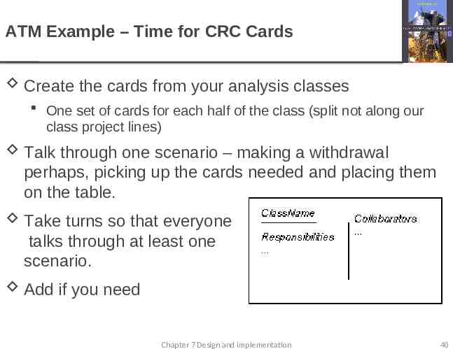
ATM Example – Time for CRC Cards Create the cards from your analysis classes One set of cards for each half of the class (split not along our class project lines) Talk through one scenario – making a withdrawal perhaps, picking up the cards needed and placing them on the table. Take turns so that everyone talks through at least one scenario. Add if you need Chapter 7 Design and implementation 40
Reminder - Design model types Static – model structure Subsystem models that show logical groupings of objects into coherent subsystems. Sequence models that show the sequence of object interactions. Dynamic – model behavior State machine models that show how individual objects change their state in response to events. Other models include use-case models Chapter 7 Design and implementation 41
ATM Example diagrams practice Create a class diagram from your classes. It should be very similar to how your cards are arranged. Quickly done on paper Include cardinality (1/1 or 1 / * or */*) Include inheritance big arrows – arrow points to the whole Create some state diagrams ATM Machine state diagram – off, serving customer, waiting ATM Session state diagram – what states occur in a session? Create some sequence diagrams customer start session diagram – using our classes Customer transaction (after logon) – using our classes Chapter 7 Design and implementation 42
ATM – check Bjork’s design http://www.math-cs.gordon.edu/courses/cps211/ ATMExample/ClassDiagram.html Class diagram Annotations Diamond Diamond attached to the class that contains another class. Often read as “has a “ from the diamond side to the non-diamond, and “is part of” from the non-diamond to the diamond. Filled diamond means the part cannot exist without the container. If the container is deleted, delete the parts. Chapter 7 Design and implementation 43
ATM – check Bjork’s design – more annotations http://www.math-cs.gordon.edu/courses/cps211/ ATMExample/ClassDiagram.html Class diagram Annotations Triangle Triangle attached to the whole in an “is a “ relationship. The class not touching the triangle “is a “ the class touching the triangle. The class touching the triangle “can be a “ the class not touching the triangle (“but it will not always be one”) Chapter 7 Design and implementation 44
ATM – check Bjork’s design – more annotations http://www.math-cs.gordon.edu/courses/cps211/ ATMExample/ClassDiagram.html Class diagram Annotations Small arrow Two classes are related, but only one knows the relationship exists The class without the arrow knows the one with the arrow exists Solid line – the arrow side is contained inside the other side Dotted line – just has a weak relationship with (maybe creates it during a method) Chapter 7 Design and implementation 45
ATM – check Bjork’s design – more annotations http://www.math-cs.gordon.edu/courses/cps211/ ATMExample/ClassDiagram.html Class diagram Annotations Dotted line - association To small arrow – depends on the small arrow side Non-arrow side “somehow depends upon” arrow side (small arrow side may be an interface) Maybe “uses’ , calls, creates, sends, instead of “depends upon” To large arrow - realizes (implements or executes) Non arrow side implements or executes arrow side Chapter 7 Design and implementation 46
ATM – check Bjork’s design – other CRC Cards: http://www.math-cs.gordon.edu/courses/cps211/ATMExa mple/CRCCards.html State diagrams: http://www.math-cs.gordon.edu/courses/cps211/ATMExa mple/Statecharts.html Sequence diagrams: http://www.math-cs.gordon.edu/courses/cps211/ATMExa mple/Interactions.html Chapter 7 Design and implementation 47
Bjork’s Subsystem model Shows how the design is organised into logically related groups of objects. In the UML, these are shown using packages - an encapsulation construct. This is a logical model. The actual organisation of objects in the system may be different. http://www.math-cs.gordon.edu/courses/cps211/ ATMExample/Package.html Chapter 7 Design and implementation 48
Interface specification – for independent work Objects Object interfaces have to be specified so that the objects and other components can be designed in parallel. Designers should avoid designing the interface representation but should hide this in the object itself. Objects may have several interfaces which are viewpoints on the methods provided. The UML uses class diagrams for interface specification Subsystems Interfaces between systems or subsystems need careful documenting so that development teams can work independently towards common goal Chapter 7 Design and implementation 49
One step lower – Detailed Design of Classes Class definition document for each class Purpose of class Roles it will play and when it will be alive in those roles Instance and class variables Static and non-static methods, with their parameters and return value, purpose, pre-conditions and post-conditions Constructor definitions Example: http://www.math-cs.gordon.edu/courses/cps211/ATMExample/D etailedDesign.html Chapter 7 Design and implementation 50
Good Class Design Not Lots of related primitive types (extract address to its own class) Not Overly complex classes – break it into two Self documenting class names Class detail design: Order elements consistently (such as constants, constructors, static methods, other methods, instance variables, static variables) Initialize data in a constructor Private data (from Project Based Software Engineering by Stiller and Leblanc – 188) Chapter 7 Design and implementation 51
Good Detailed Design Verification Trace to requirements Every element in requirements shows up in design Walk Through Meet with ALL developers (not users) to talk through scenarios, tracing classes and method calls Ensure agreement of method signatures (input/ output) by both caller and method developer (from Project Based Software Engineering by Stiller and Leblanc – 188) Chapter 7 Design and implementation 52
User Interface Design Doc Show all user interactions Screens Reports For VRU: menus and messages Chapter 7 Design and implementation 53
User Interface Design Doc – good practices User Interface design good practices Be consistent Provide shortcuts Offer useful feedback and help Prevent catastrophic mistakes Verify deletion tasks Allow easy reversal of most actions Make user focus on task, not interface Do not rely on user memory Display only currently relevant information (from Project Based Software Engineering by Stiller and Leblanc – 188) Chapter 7 Design and implementation 54
User Interface – Icon design Easy to understand icons Avoid misleading analogies for the icon Do not violate population stereotypes Use icons for appropriate purposes Carefully design the iconic interaction (from Project Based Software Engineering by Stiller and Leblanc – 188) Chapter 7 Design and implementation 55
Key points Software design and implementation are inter-leaved activities. The level of detail in the design depends on the type of system and whether you are using a plan-driven or agile approach. Determine classes by grammar, tangible, scenario or behavior. Look for entity, control and boundary objects. Can start with use case. CRC Cards can help define classes. Class / Responsibility / Collaborator models - static models (class models, generalization models, association models) and dynamic models (sequence models, state machine models). Subsystem and Component interfaces definition is necessary to divide work Chapter 7 Design and implementation 56