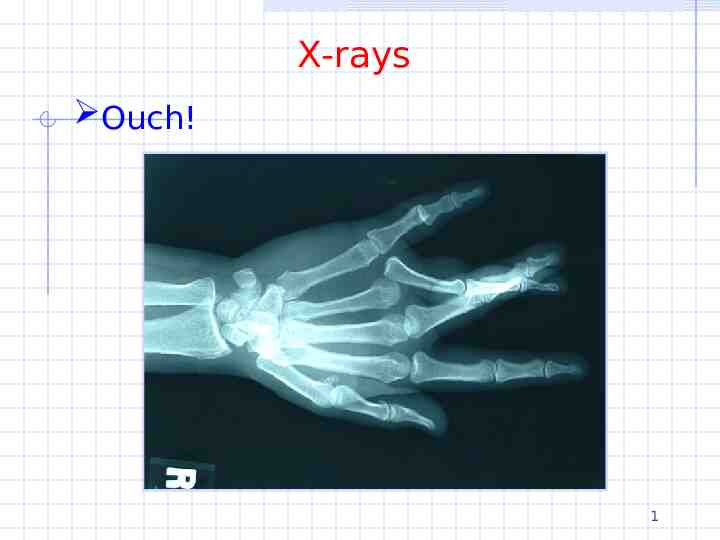
X-rays Ouch! 1

60 Slides4.00 MB
X-rays Ouch! 1
X-rays X-rays are produced when electrons are accelerated and collide with a target Bremsstrahlung x-rays Characteristic x-rays X-rays are sometimes characterized by the generating voltage 0.1-20 kV 20-120 kV 120-300 kV 300 kV – 1 MV 1MV soft x-rays diagnostic x-rays orthovoltage x-rays intermediate energy x-rays megavoltage x-rays 2
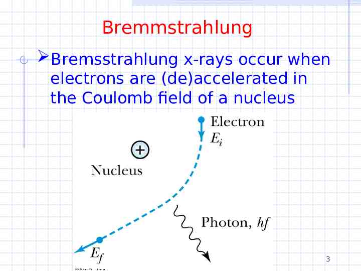
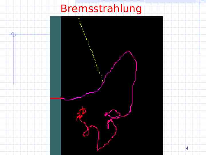
Bremmstrahlung Bremsstrahlung x-rays occur when electrons are (de)accelerated in the Coulomb field of a nucleus 3
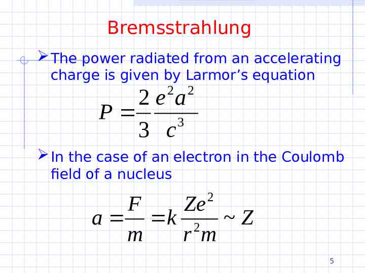
Bremsstrahlung 4
Bremsstrahlung The power radiated from an accelerating charge is given by Larmor’s equation 2 2e a P 3 3 c 2 In the case of an electron in the Coulomb field of a nucleus 2 F Ze a k 2 Z m r m 5
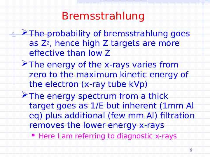
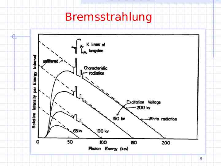
Bremsstrahlung The probability of bremsstrahlung goes as Z2, hence high Z targets are more effective than low Z The energy of the x-rays varies from zero to the maximum kinetic energy of the electron (x-ray tube kVp) The energy spectrum from a thick target goes as 1/E but inherent (1mm Al eq) plus additional (few mm Al) filtration removes the lower energy x-rays Here I am referring to diagnostic x-rays 6
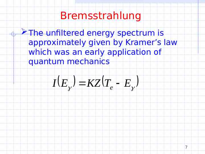
Bremsstrahlung The unfiltered energy spectrum is approximately given by Kramer’s law which was an early application of quantum mechanics I E KZ Te E 7
Bremsstrahlung 8
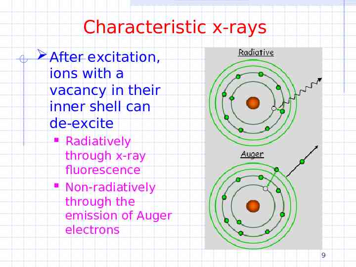
Characteristic x-rays After excitation, ions with a vacancy in their inner shell can de-excite Radiatively through x-ray fluorescence Non-radiatively through the emission of Auger electrons 9
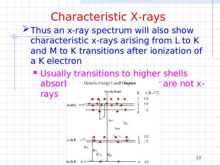
Characteristic X-rays Thus an x-ray spectrum will also show characteristic x-rays arising from L to K and M to K transitions after ionization of a K electron Usually transitions to higher shells absorbed by the filtration or are not xrays 10
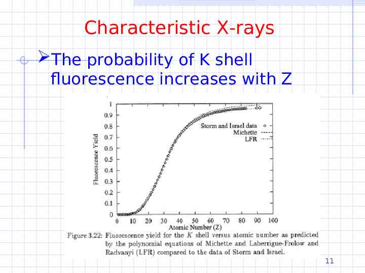
Characteristic X-rays The probability of K shell fluorescence increases with Z 11
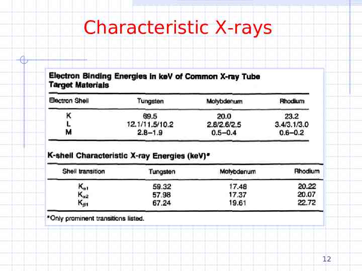
Characteristic X-rays 12
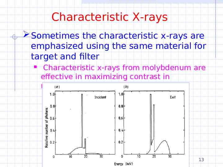
Characteristic X-rays Sometimes the characteristic x-rays are emphasized using the same material for target and filter Characteristic x-rays from molybdenum are effective in maximizing contrast in mammography 13
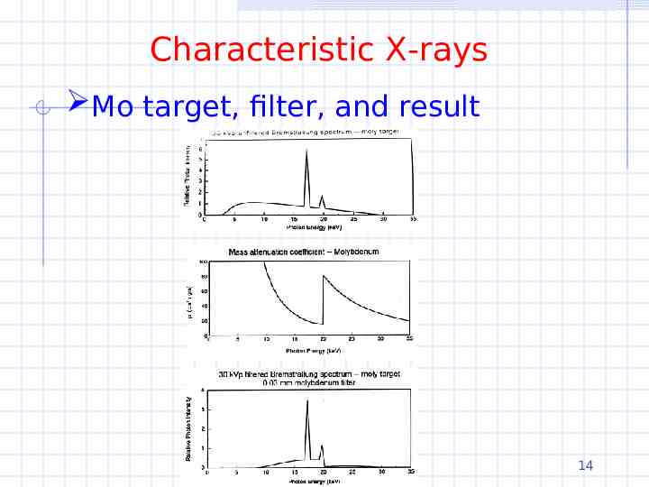
Characteristic X-rays Mo target, filter, and result 14
Directionality For MeV electrons, bremsstrahlung x-rays are preferentially emitted in the electron’s direction For keV electrons, bremsstrahlung x-rays are emitted at larger angles Characteristic x-rays are emitted isotropically since there is no angular correlation between the incident electron that causes the ionization and the fluorescent photon 15
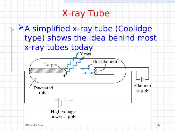
X-ray Tube A simplified x-ray tube (Coolidge type) shows the idea behind most x-ray tubes today 16
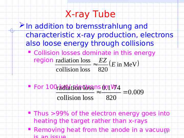
X-ray Tube In addition to bremsstrahlung and characteristic x-ray production, electrons also loose energy through collisions Collision losses dominate in this energy region radiation loss EZ collision loss For 100radiation keV electrons loss 0in.1W 74 collision loss 820 E in MeV 820 0.009 Thus 99% of the electron energy goes into heating the target rather than x-rays Removing heat from the anode in a vacuum 17
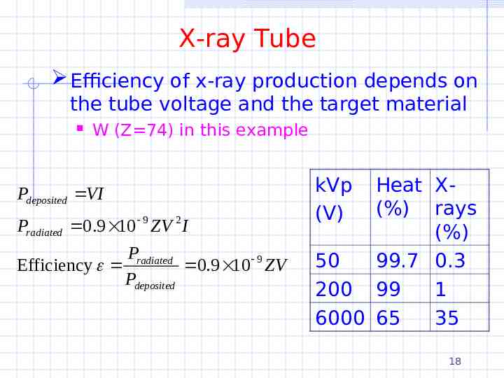
X-ray Tube Efficiency of x-ray production depends on the tube voltage and the target material W (Z 74) in this example Pdeposited VI Pradiated 0.9 10 9 ZV 2 I Pradiated Efficiency 0.9 10 9 ZV Pdeposited kVp (V) Heat X(%) rays (%) 50 99.7 0.3 200 99 1 6000 65 35 18
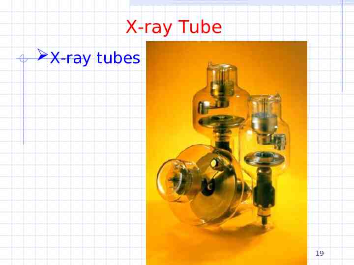
X-ray Tube X-ray tubes 19
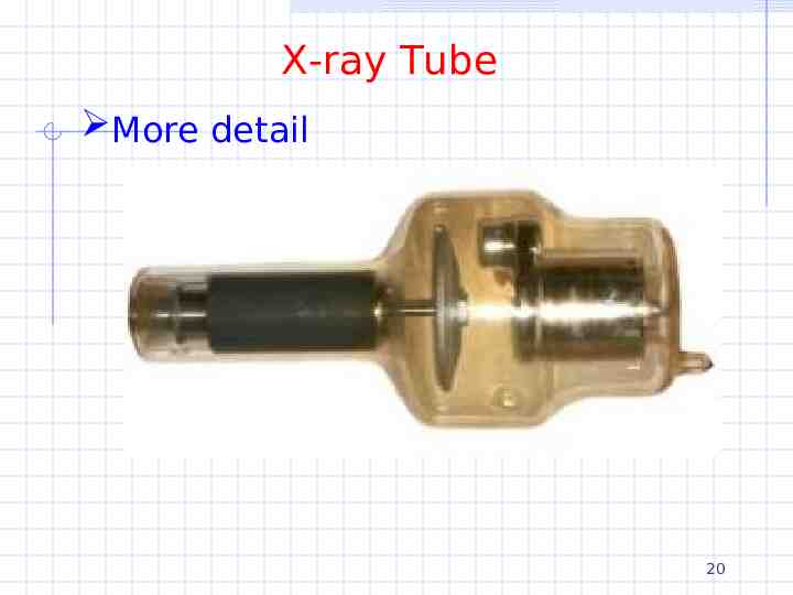
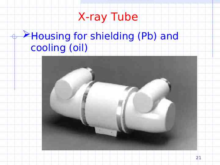
X-ray Tube More detail 20
X-ray Tube Housing for shielding (Pb) and cooling (oil) 21
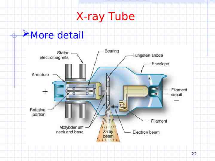
X-ray Tube More detail 22
X-ray Tube The main parts of the x-ray tube are Cathode/filament Typical electron current is 0.1-1.0 A for short exposures ( 100 ms) Anode/target Glass/metal envelope Accelerating voltage Typical voltage is 20-150 kVp 23
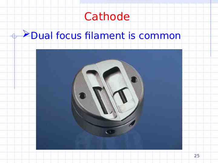
Cathode Cathode consists of Low R tungsten wire for thermionic emission Tungsten has a high melting point (3370C) and minimum deposit on the glass tube Tube current is controlled by varying the filament current which is a few amps A focusing cup Uses electric field lines to focus the electrons Typically there are two filaments Long one: higher current, lower resolution Large focal spot Short one: lower current, higher resolution Small focal spot 24
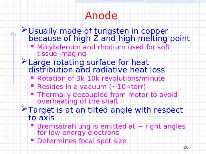
Cathode Dual focus filament is common 25
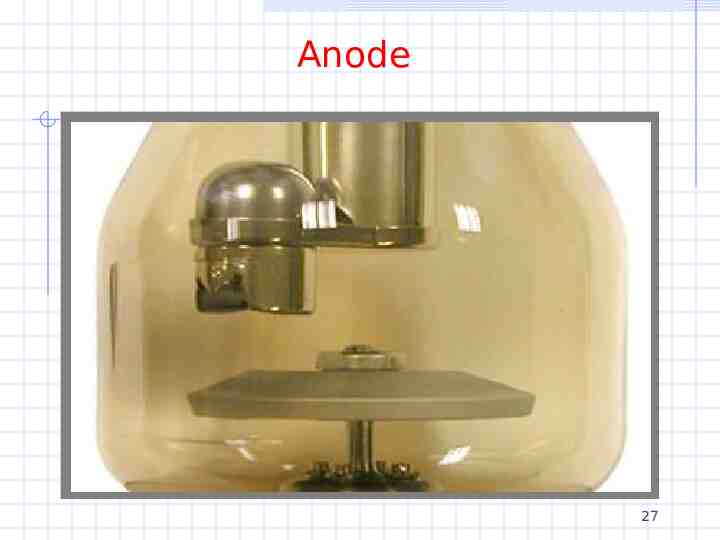
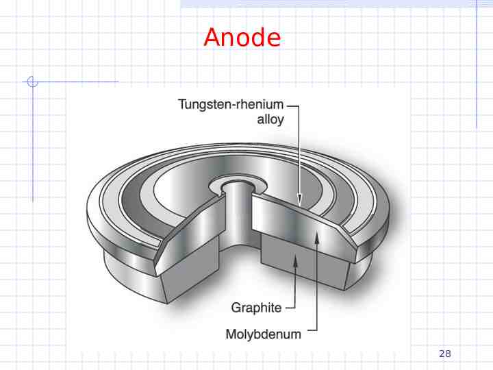
Anode Usually made of tungsten in copper because of high Z and high melting point Molybdenum and rhodium used for soft tissue imaging Large rotating surface for heat distribution and radiative heat loss Rotation of 3k-10k revolutions/minute Resides in a vacuum ( 10-6 torr) Thermally decoupled from motor to avoid overheating of the shaft Target is at an tilted angle with respect to axis Bremsstrahlung is emitted at right angles for low energy electrons Determines focal spot size 26
Anode 27
Anode 28
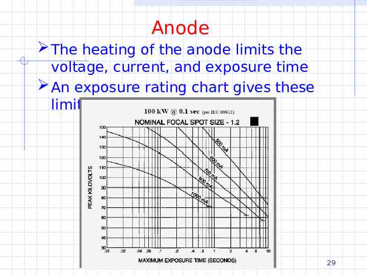
Anode The heating of the anode limits the voltage, current, and exposure time An exposure rating chart gives these limits 29
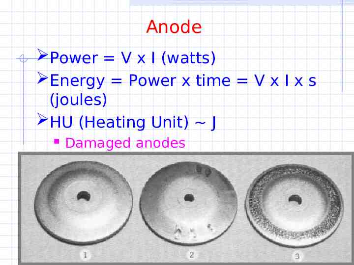
Anode Power V x I (watts) Energy Power x time V x I x s (joules) HU (Heating Unit) J Damaged anodes 30
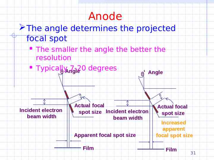
Anode The angle determines the projected focal spot The smaller the angle the better the resolution Typically 7-20 degrees Angle ‘ Incident electron beam width Angle Actual focal spot size Incident electron beam width Apparent focal spot size Film Actual focal spot size Increased apparent focal spot size Film 31
X-rays The energy of the photons depends on the electron energy (kVp) and the target atomic number Z The number of photons depends on the the electron energy (kVp), Z, and the beam current (mA) A typical number / area is 1013 / m2 About 1% will hit the film 1011 / m2 Absorption and detection efficiency will further reduce this number 32
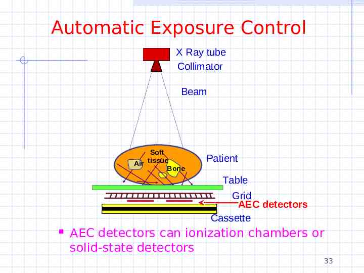
Automatic Exposure Control X Ray tube Collimator Beam Soft Air tissue Bone Patient Table Grid AEC detectors Cassette AEC detectors can ionization chambers or solid-state detectors 33
Automatic Exposure Control Most modern x-rays machines are equipped with automatic exposure control also called a phototime The AEC sets the technical parameters of the machine (kV, mA, time, ) in order to avoid repeated exposures AEC is used to keep the radiographic quality (film density) equal on all patients AEC detectors can be ionization chambers or solid state detectors 34
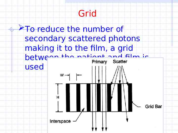
Grid To reduce the number of secondary scattered photons making it to the film, a grid between the patient and film is used 35
Details Grid Grid bars are usually lead whereas the grid openings are usually made of aluminum or carbon Grid thickness is typically 3 mm Grid ratio is H/W and 10/1 is typical Grid frequency of 60 lines / cm is typical B/W/H on the figure might be 0.045, 0.120, 1.20 in mm The Bucky factor is the entrance exposure w/wo the grid while achieving the same film density – 4 is average 36
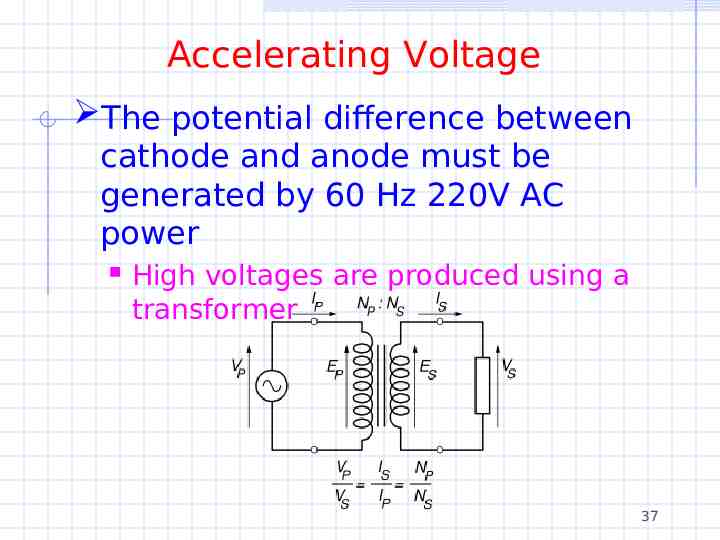
Accelerating Voltage The potential difference between cathode and anode must be generated by 60 Hz 220V AC power High voltages are produced using a transformer 37
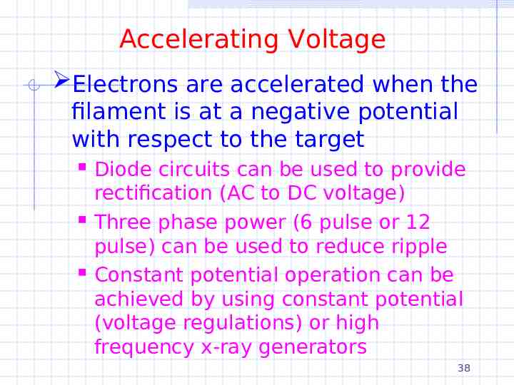
Accelerating Voltage Electrons are accelerated when the filament is at a negative potential with respect to the target Diode circuits can be used to provide rectification (AC to DC voltage) Three phase power (6 pulse or 12 pulse) can be used to reduce ripple Constant potential operation can be achieved by using constant potential (voltage regulations) or high frequency x-ray generators 38
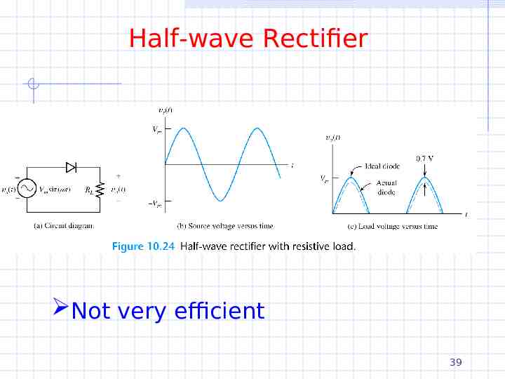
Half-wave Rectifier Not very efficient 39
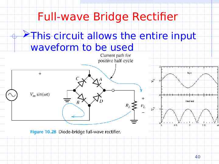
Full-wave Bridge Rectifier This circuit allows the entire input waveform to be used 40
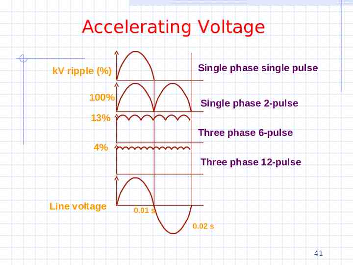
Accelerating Voltage Single phase single pulse kV ripple (%) 100% Single phase 2-pulse 13% Three phase 6-pulse 4% Three phase 12-pulse Line voltage 0.01 s 0.02 s 41
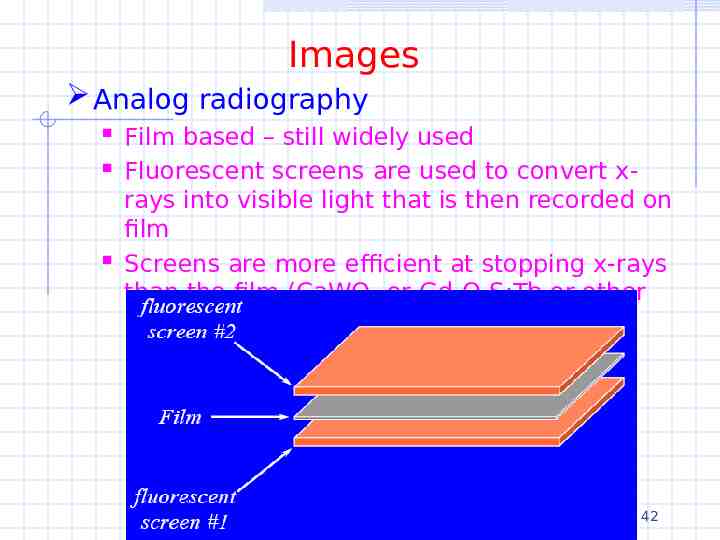
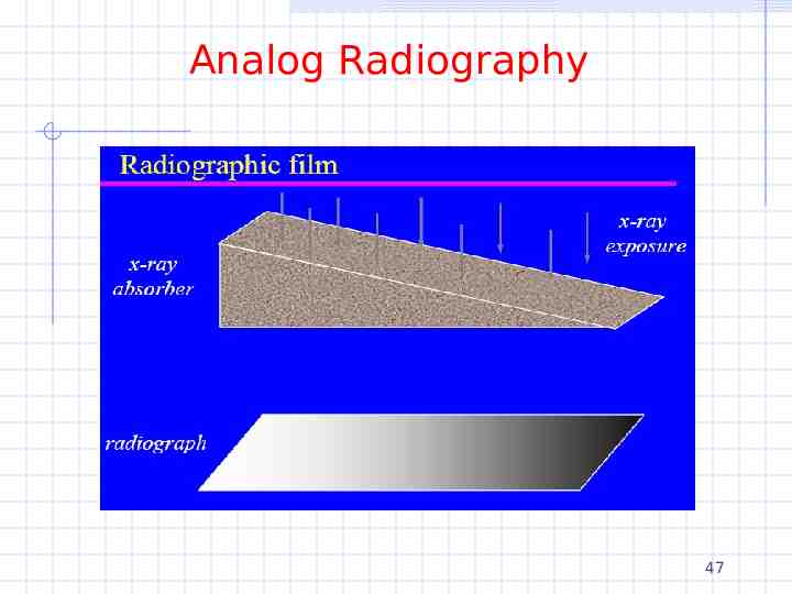
Images Analog radiography Film based – still widely used Fluorescent screens are used to convert xrays into visible light that is then recorded on film Screens are more efficient at stopping x-rays than the film (CaWO4 or Gd2O2S:Tb or other rare earth) 42
Analog Radiography The film itself has excellent spatial resolution but Film detects 0.65% of incident x-ray energy Gd2O2S detects 29.5% of incident x-ray energy Thus using phosphor screens greatly reduces the radiation dose to the patient And also reduces load on the x-ray tube 43
Analog Radiography There are two efficiency considerations Absorption efficiency or QDE Fraction of incident x-rays that interact with the screen Depends on kVp and screen thickness Gd2O2S has a QDE of 60% for 80 kVp beam, 20 cm patient, 120 mg/cm2 screen thickness 44
Analog Radiography Conversion efficiency Fraction of absorbed x-ray energy that is emitted as light 5% for CaWO4 15% for Gd2O2S 50,000 eV x 0.15 7500 eV 7500 eV / 2.7 eV 2800 photons produced per absorbed x-ray 50-90% reduction in photon diffusion to film 45
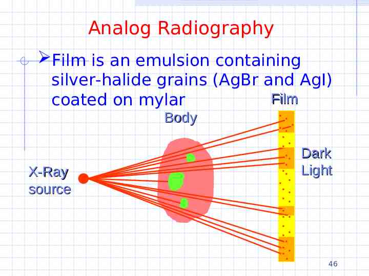
Analog Radiography Film is an emulsion containing silver-halide grains (AgBr and AgI) Film coated on mylar Body X-Ray source Dark Light 46
Analog Radiography 47
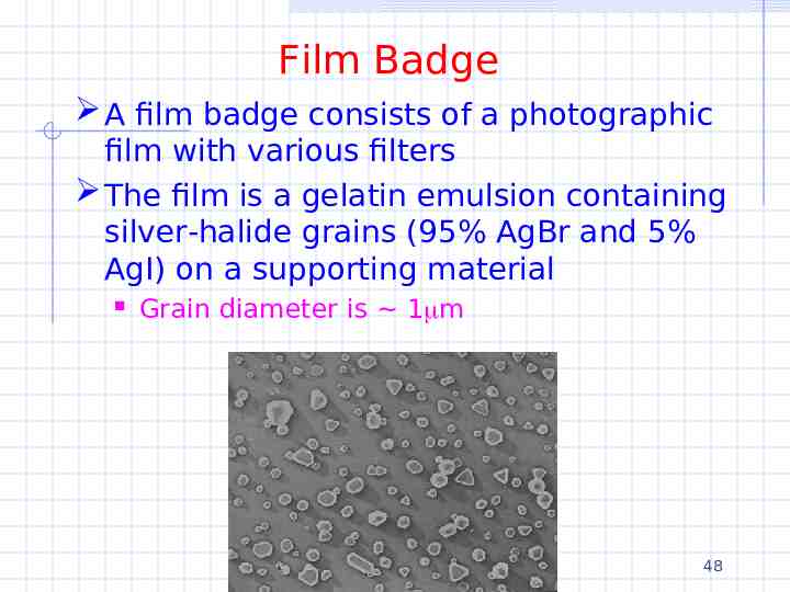
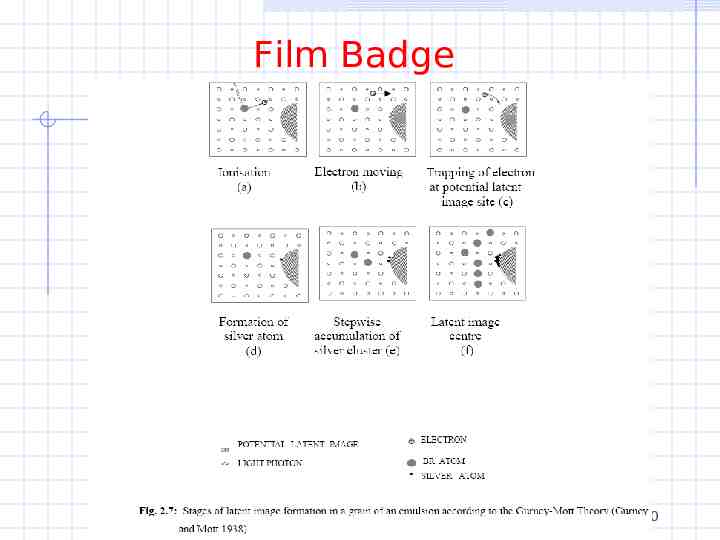
Film Badge A film badge consists of a photographic film with various filters The film is a gelatin emulsion containing silver-halide grains (95% AgBr and 5% AgI) on a supporting material Grain diameter is 1 m 48
Film Badge The film is exposed by light by An electron is released from Br- and moves about the 1 diameter crystal The electron may be captured by a trap such as a crystal imperfection or AgS speck The trapped electron attracts mobile Ag ions where it is subsequently neutralized Additional Ag atoms are formed by repeated trapping and neutralization These Ag atoms are called a latent image center The developing process effectively amplifies this process turning the grains with latent image centers into a visible silver deposit 49
Film Badge 50
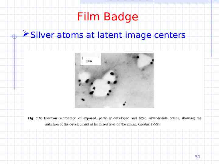
Film Badge Silver atoms at latent image centers 51
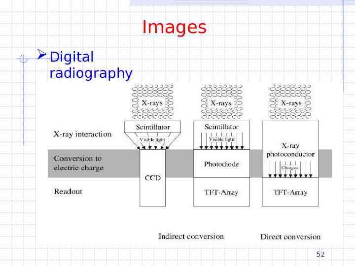
Images Digital radiography Detector based 52
Digitial Radiography CCD systems CCD systems use a scintillator like gadolinium disulphide to convert x-rays to visible light Light is collected by optics to demagnify the 35x45cm2 film to 2-4 cm2 CCD We’ll talk about CCD’s much later in the course but essentially visible light is converted into charge that is amplified and readout A negative is the thickness of the detector system because of the optical 53 system
Digital Radiography Indirect or direct conversion thin-film transistor (TFT) arrays Also called FPD (flat panel detectors) We’ll cover these later in the course as well – probably through a student talk The idea is that charge proportional to the x-rays received is stored on a capacitor The charges are conducted out by transistors one row at a time and subsequently amplified, multiplexed, and digitized The readout is very fast 54
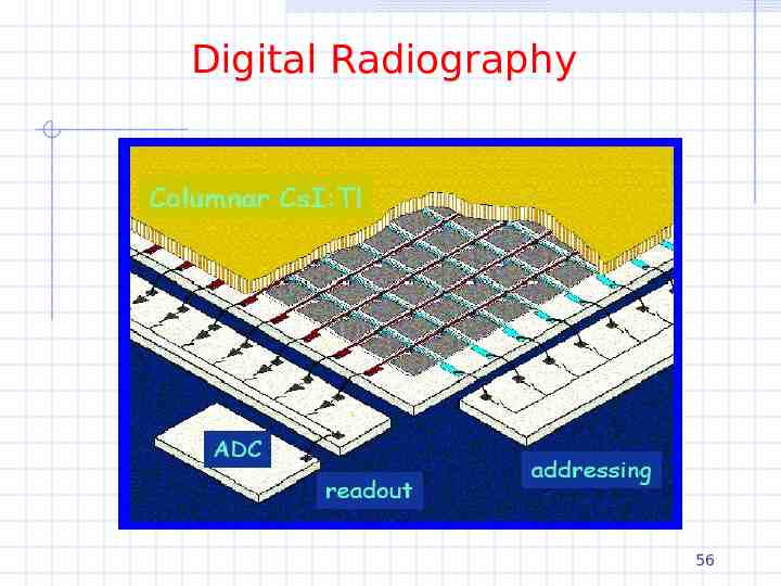
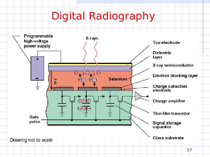
Digital Radiography Indirect or direct conversion thin-film transistor (TFT) arrays Indirect conversion uses a scintillator layer (like CsI:Tl) to convert x-rays to visible light and amorphous silicon photodiodes to convert visible light into charge Direct conversion uses an x-ray photoconductor layer (usually amorphous selenium) to convert x-rays to charge An applied electric field directs the charges to the charge collection electrodes 55
Digital Radiography 56
Digital Radiography 57
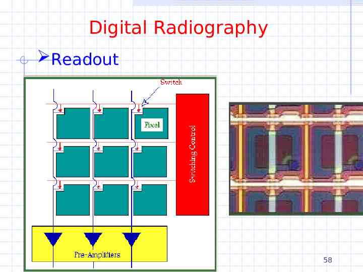
Digital Radiography Readout 58
Images Digital radiography “The battle over image quality, however, may be incomprehensible to anyone without a background in highenergy physics.” 59
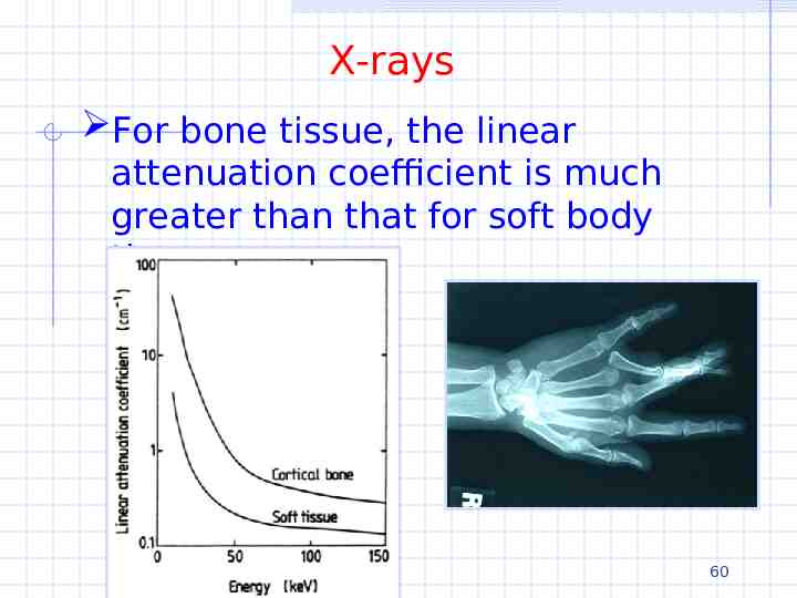
X-rays For bone tissue, the linear attenuation coefficient is much greater than that for soft body tissue 60