Transit Bus Emissions Control Systems Day 1: Servicing Intake


57 Slides3.54 MB
Transit Bus Emissions Control Systems Day 1: Servicing Intake and Exhaust Systems, EGR and DOC Operations, Service and Troubleshooting
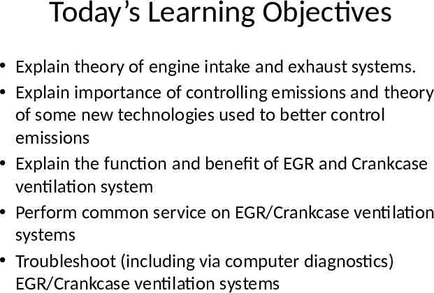
Today’s Learning Objectives Explain theory of engine intake and exhaust systems. Explain importance of controlling emissions and theory of some new technologies used to better control emissions Explain the function and benefit of EGR and Crankcase ventilation system Perform common service on EGR/Crankcase ventilation systems Troubleshoot (including via computer diagnostics) EGR/Crankcase ventilation systems
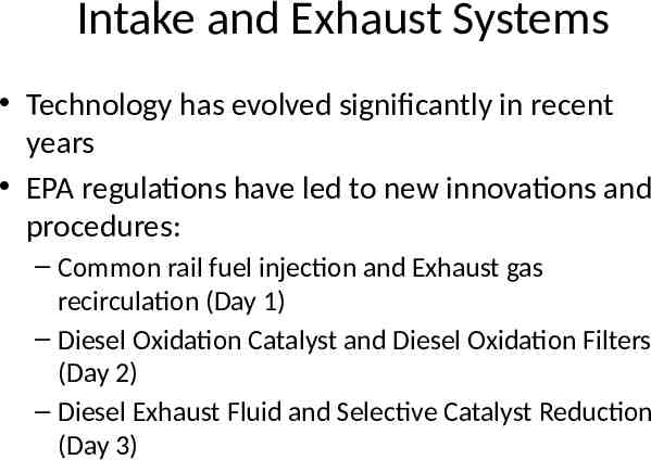
Intake and Exhaust Systems Technology has evolved significantly in recent years EPA regulations have led to new innovations and procedures: – Common rail fuel injection and Exhaust gas recirculation (Day 1) – Diesel Oxidation Catalyst and Diesel Oxidation Filters (Day 2) – Diesel Exhaust Fluid and Selective Catalyst Reduction (Day 3)
EGR / Crankcase Ventilation Systems Installed on 2005/2006 Buses at UTA We will walkthrough documentation from Cummins Quickserve for a 2006 ISB Engine (#46573883)
EGR / Crankcase Ventilation Systems Operations
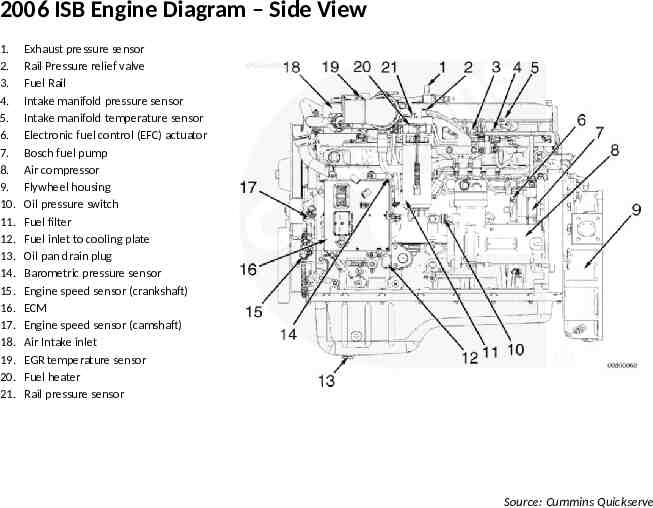
2006 ISB Engine Diagram – Side View 1. 2. 3. 4. 5. 6. 7. 8. 9. 10. 11. 12. 13. 14. 15. 16. 17. 18. 19. 20. 21. Exhaust pressure sensor Rail Pressure relief valve Fuel Rail Intake manifold pressure sensor Intake manifold temperature sensor Electronic fuel control (EFC) actuator Bosch fuel pump Air compressor Flywheel housing Oil pressure switch Fuel filter Fuel inlet to cooling plate Oil pan drain plug Barometric pressure sensor Engine speed sensor (crankshaft) ECM Engine speed sensor (camshaft) Air Intake inlet EGR temperature sensor Fuel heater Rail pressure sensor Source: Cummins Quickserve
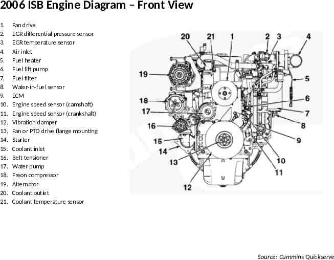
2006 ISB Engine Diagram – Front View 1. 2. 3. 4. 5. 6. 7. 8. 9. 10. 11. 12. 13. 14. 15. 16. 17. 18. 19. 20. 21. Fan drive EGR differential pressure sensor EGR temperature sensor Air inlet Fuel heater Fuel lift pump Fuel filter Water-in-fuel sensor ECM Engine speed sensor (camshaft) Engine speed sensor (crankshaft) Vibration damper Fan or PTO drive flange mounting Starter Coolant inlet Belt tensioner Water pump Freon compressor Alternator Coolant outlet Coolant temperature sensor Source: Cummins Quickserve
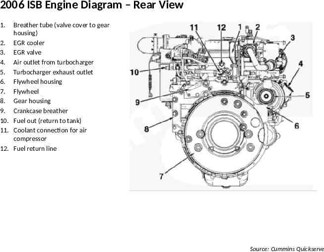
2006 ISB Engine Diagram – Rear View 1. Breather tube (valve cover to gear housing) 2. EGR cooler 3. EGR valve 4. Air outlet from turbocharger 5. Turbocharger exhaust outlet 6. Flywheel housing 7. Flywheel 8. Gear housing 9. Crankcase breather 10. Fuel out (return to tank) 11. Coolant connection for air compressor 12. Fuel return line Source: Cummins Quickserve
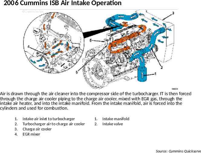
2006 Cummins ISB Air Intake Operation Air is drawn through the air cleaner into the compressor side of the turbocharger. IT is then forced through the charge air cooler piping to the charge air cooler, mixed with EGR gas, through the intake air heater, and into the intake manifold. From the intake manifold, air is forced into the cylinders and used for combustion. 1. 2. 3. 4. Intake air inlet to turbocharger Turbocharger air to charge air cooler Charge air cooler EGR mixer 1. 2. Intake manifold Intake valve Source: Cummins Quickserve
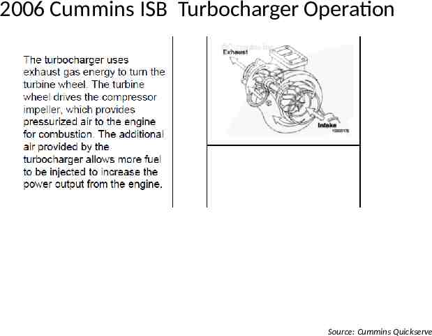
2006 Cummins ISB Turbocharger Operation Source: Cummins Quickserve
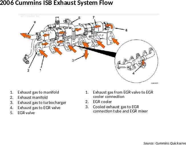
2006 Cummins ISB Exhaust System Flow 1. 2. 3. 4. 5. Exhaust gas to manifold Exhaust manifold Exhaust gas to turbocharger Exhaust gas to EGR valve EGR valve 1. 2. 3. Exhaust gas from EGR valve to EGR cooler connection EGR cooler Cooled exhaust gas to EGR connection tube and EGR mixer Source: Cummins Quickserve
Notes on Other Engines There are Detroit Diesels at UTA with similar EGR/Crankcase ventilation operations There are also other similar Cummins engines, this model is used as a representative sample Later model engines with DPF w/DOC or DEF w/ SCR approaches will be discussed on Days 2 and 3 of training
EGR / Crankcase Ventilation Systems Service
Emissions System Service EGR Cleaning procedures Cleaning out Delta-p sensor EGR Valve EGR Cooler EGR Pipes
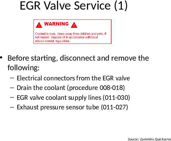
EGR Valve Service (1) Before starting, disconnect and remove the following: – – – – Electrical connectors from the EGR valve Drain the coolant (procedure 008-018) EGR valve coolant supply lines (011-030) Exhaust pressure sensor tube (011-027) Source: Cummins Quickserve
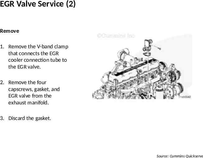
EGR Valve Service (2) Remove 1. Remove the V-band clamp that connects the EGR cooler connection tube to the EGR valve. 2. Remove the four capscrews, gasket, and EGR valve from the exhaust manifold. 3. Discard the gasket. Source: Cummins Quickserve
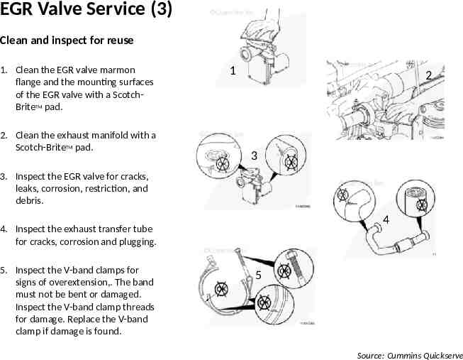
EGR Valve Service (3) Clean and inspect for reuse 1. Clean the EGR valve marmon flange and the mounting surfaces of the EGR valve with a ScotchBriteTM pad. 2. Clean the exhaust manifold with a Scotch-BriteTM pad. 1 2 3 3. Inspect the EGR valve for cracks, leaks, corrosion, restriction, and debris. 4 4. Inspect the exhaust transfer tube for cracks, corrosion and plugging. 5. Inspect the V-band clamps for signs of overextension,. The band must not be bent or damaged. Inspect the V-band clamp threads for damage. Replace the V-band clamp if damage is found. 5 Source: Cummins Quickserve
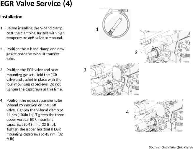
EGR Valve Service (4) Installation 1. Before installing the V-band clamp, coat the clamping surface with high temperature anti-seize compound. 1 2. Position the V-band clamp and new gasket onto the exhaust transfer tube. 3. Position the EGR valve and new mounting gasket. Hold the EGR valve and gasket in place with the four mounting capscrews. Do not tighten the capscrews at this time. 4. Position the exhaust transfer tube V-band connection on the EGR valve. Tighten the V-band clamp to 11 nm [100in-lb]. Tighten the three upper vertical EGR mounting capscrews to 43 nm. [32 ft-lb]. Tighten the upper horizontal EGR mounting capscrews to 43 nm. [32 ft-lb] 2 3 4 Source: Cummins Quickserve
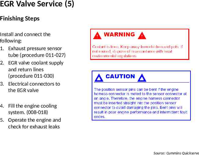
EGR Valve Service (5) Finishing Steps Install and connect the following: 1. Exhaust pressure sensor tube (procedure 011-027) 2. EGR valve coolant supply and return lines (procedure 011-030) 3. Electrical connectors to the EGR valve 2 4. Fill the engine cooling system. (008-018) 5. Operate the engine and check for exhaust leaks Source: Cummins Quickserve
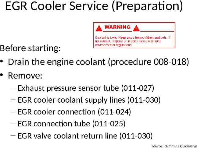
EGR Cooler Service (Preparation) Before starting: Drain the engine coolant (procedure 008-018) Remove: – Exhaust pressure sensor tube (011-027) – EGR cooler coolant supply lines (011-030) – EGR cooler connection (011-024) – EGR connection tube (011-025) – EGR valve coolant return line (011-030) Source: Cummins Quickserve
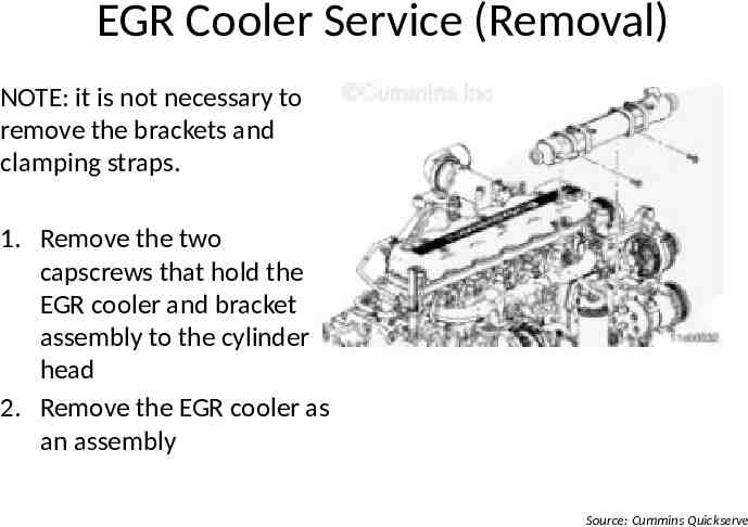
EGR Cooler Service (Removal) NOTE: it is not necessary to remove the brackets and clamping straps. 1. Remove the two capscrews that hold the EGR cooler and bracket assembly to the cylinder head 2. Remove the EGR cooler as an assembly Source: Cummins Quickserve
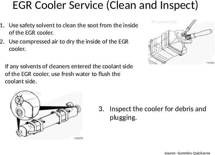
EGR Cooler Service (Clean and Inspect) 1. Use safety solvent to clean the soot from the inside of the EGR cooler. 2. Use compressed air to dry the inside of the EGR cooler. If any solvents of cleaners entered the coolant side of the EGR cooler, use fresh water to flush the coolant side. 3. Inspect the cooler for debris and plugging. Source: Cummins Quickserve
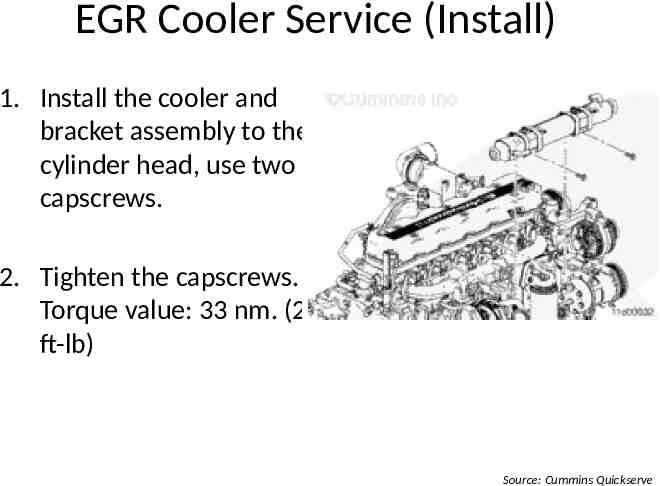
EGR Cooler Service (Install) 1. Install the cooler and bracket assembly to the cylinder head, use two capscrews. 2. Tighten the capscrews. Torque value: 33 nm. (24 ft-lb) Source: Cummins Quickserve
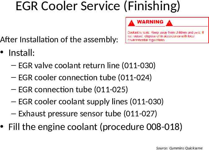
EGR Cooler Service (Finishing) After Installation of the assembly: Install: – EGR valve coolant return line (011-030) – EGR cooler connection tube (011-024) – EGR connection tube (011-025) – EGR cooler coolant supply lines (011-030) – Exhaust pressure sensor tube (011-027) Fill the engine coolant (procedure 008-018) Source: Cummins Quickserve
Other Service procedures Exhaust gas pressure sensor tube EGR Valve coolant lines EGR cooler coolant lines Do these cover the other topics listed in the lesson plan? Are there other procedures that need to be discussed?
EGR / Crankcase Ventilation Systems Troubleshooting
EGR / Crankcase Ventilation Problems Intake Manifold pressure (boost) low Intake Air Temp above spec Turbocharger leaks engine oil or fuel What other common or difficult problems do you see on these and similar engines? How have you addressed them?
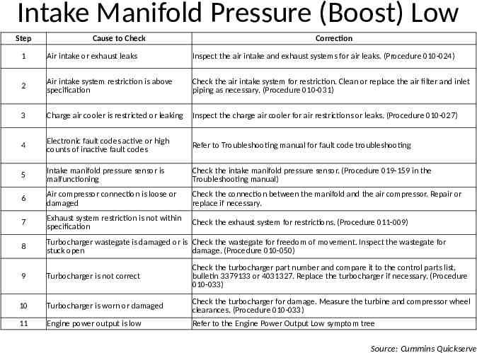
Intake Manifold Pressure (Boost) Low Step Cause to Check Correction 1 Air intake or exhaust leaks Inspect the air intake and exhaust systems for air leaks. (Procedure 010-024) 2 Air intake system restriction is above specification Check the air intake system for restriction. Clean or replace the air filter and inlet piping as necessary. (Procedure 010-031) 3 Charge air cooler is restricted or leaking Inspect the charge air cooler for air restrictions or leaks. (Procedure 010-027) 4 Electronic fault codes active or high counts of inactive fault codes Refer to Troubleshooting manual for fault code troubleshooting 5 Intake manifold pressure sensor is malfunctioning Check the intake manifold pressure sensor. (Procedure 019-159 in the Troubleshooting manual) 6 Air compressor connection is loose or damaged Check the connection between the manifold and the air compressor. Repair or replace if necessary. 7 Exhaust system restriction is not within specification Check the exhaust system for restrictions. (Procedure 011-009) 8 Turbocharger wastegate is damaged or is Check the wastegate for freedom of movement. Inspect the wastegate for stuck open damage. (Procedure 010-050) 9 Turbocharger is not correct Check the turbocharger part number and compare it to the control parts list, bulletin 3379133 or 4031327. Replace the turbocharger if necessary. (Procedure 010-033) 10 Turbocharger is worn or damaged Check the turbocharger for damage. Measure the turbine and compressor wheel clearances. (Procedure 010-033) 11 Engine power output is low Refer to the Engine Power Output Low symptom tree Source: Cummins Quickserve
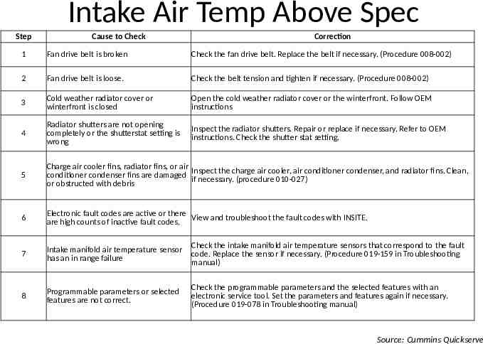
Intake Air Temp Above Spec Step Cause to Check Correction 1 Fan drive belt is broken Check the fan drive belt. Replace the belt if necessary. (Procedure 008-002) 2 Fan drive belt is loose. Check the belt tension and tighten if necessary. (Procedure 008-002) 3 Cold weather radiator cover or winterfront is closed Open the cold weather radiator cover or the winterfront. Follow OEM instructions 4 Radiator shutters are not opening completely or the shutterstat setting is wrong Inspect the radiator shutters. Repair or replace if necessary. Refer to OEM instructions. Check the shutter stat setting. 5 Charge air cooler fins, radiator fins, or air Inspect the charge air cooler, air conditioner condenser, and radiator fins. Clean, conditioner condenser fins are damaged if necessary. (procedure 010-027) or obstructed with debris 6 Electronic fault codes are active or there View and troubleshoot the fault codes with INSITE. are high counts of inactive fault codes. 7 Intake manifold air temperature sensor has an in range failure Check the intake manifold air temperature sensors that correspond to the fault code. Replace the sensor if necessary. (Procedure 019-159 in Troubleshooting manual) 8 Programmable parameters or selected features are not correct. Check the programmable parameters and the selected features with an electronic service tool. Set the parameters and features again if necessary. (Procedure 019-078 in Troubleshooting manual) Source: Cummins Quickserve
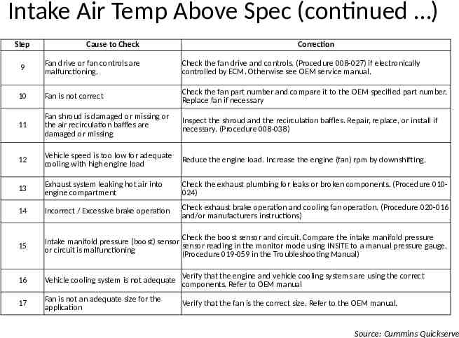
Intake Air Temp Above Spec (continued ) Step Cause to Check Correction 9 Fan drive or fan controls are malfunctioning. Check the fan drive and controls. (Procedure 008-027) if electronically controlled by ECM. Otherwise see OEM service manual. 10 Fan is not correct Check the fan part number and compare it to the OEM specified part number. Replace fan if necessary 11 Fan shroud is damaged or missing or the air recirculation baffles are damaged or missing Inspect the shroud and the recirculation baffles. Repair, replace, or install if necessary. (Procedure 008-038) 12 Vehicle speed is too low for adequate cooling with high engine load Reduce the engine load. Increase the engine (fan) rpm by downshifting. 13 Exhaust system leaking hot air into engine compartment Check the exhaust plumbing for leaks or broken components. (Procedure 010024) 14 Incorrect / Excessive brake operation Check exhaust brake operation and cooling fan operation. (Procedure 020-016 and/or manufacturers instructions) 15 Check the boost sensor and circuit. Compare the intake manifold pressure Intake manifold pressure (boost) sensor sensor reading in the monitor mode using INSITE to a manual pressure gauge. or circuit is malfunctioning (Procedure 019-059 in the Troubleshooting Manual) 16 Vehicle cooling system is not adequate Verify that the engine and vehicle cooling systems are using the correct components. Refer to OEM manual 17 Fan is not an adequate size for the application Verify that the fan is the correct size. Refer to the OEM manual. Source: Cummins Quickserve
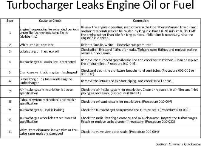
Turbocharger Leaks Engine Oil or Fuel Step Cause to Check Correction 1 Review the engine operating instructions in the Operations Manual. Low oil and Engine is operating for extended periods coolant temperatures can be caused by long idle times ( 10 minutes). Shut off under light or no-load conditions the engine rather than idle for long periods. If idle time is necessary, raise the (slobbering) engine / idle speed. 2 White smoke is present 3 Lubricating oil lines leak oil 4 Turbocharger oil drain line is restricted. Remove the turbocharger oil drain line and check for restriction. Clean or replace the oil drain line. (Procedure 010-045) 5 Crankcase ventilation system is plugged Check and clean the crankcase breather and vent tube. (Procedure 003-002 or 003-018) 6 Lubricating oil or fuel is entering the turbocharger Remove the intake and exhaust piping, and check for oil or fuel 7 Air intake system restriction is above specification Check the air intake system for restriction. Clean or replace the air filter and inlet piping as necessary. (Procedure 010-031) 8 Exhaust system restriction is not within specification Check the exhaust system for restrictions. (Procedure 010-009) 9 Turbocharger oil seal is leaking Check the turbocharger compressor and turbine seals (Procedure 010-033) 10 Turbocharger wheel clearance is out of specification Check the radial bearing clearance and axial clearance. Inspect the turbocharger. Repair or replace turbocharger if necessary. (Procedure 010-033) 11 Valve stem clearance is excessive or the valve stem seals are damaged Check the valve stems and seals. (Procedure 002-004) Refer to Smoke, white -- Excessive symptom tree Check all oil lines and fittings for leaks. Tighten loose fittings and replace leaking oil lines if necessary. Source: Cummins Quickserve
EGR / Crankcase Ventilation Systems Computer Diagnostics
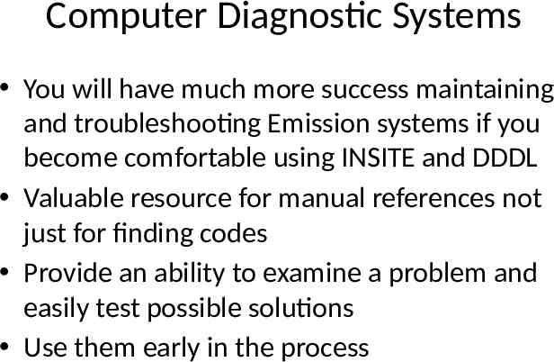
Computer Diagnostic Systems You will have much more success maintaining and troubleshooting Emission systems if you become comfortable using INSITE and DDDL Valuable resource for manual references not just for finding codes Provide an ability to examine a problem and easily test possible solutions Use them early in the process
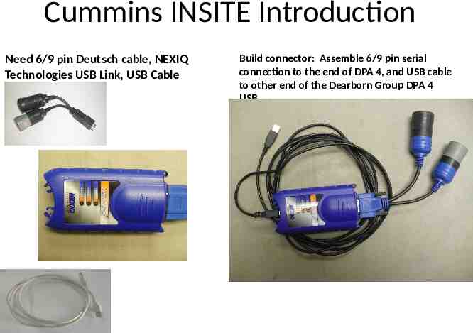
Cummins INSITE Introduction Need 6/9 pin Deutsch cable, NEXIQ Technologies USB Link, USB Cable Build connector: Assemble 6/9 pin serial connection to the end of DPA 4, and USB cable to other end of the Dearborn Group DPA 4 USB.
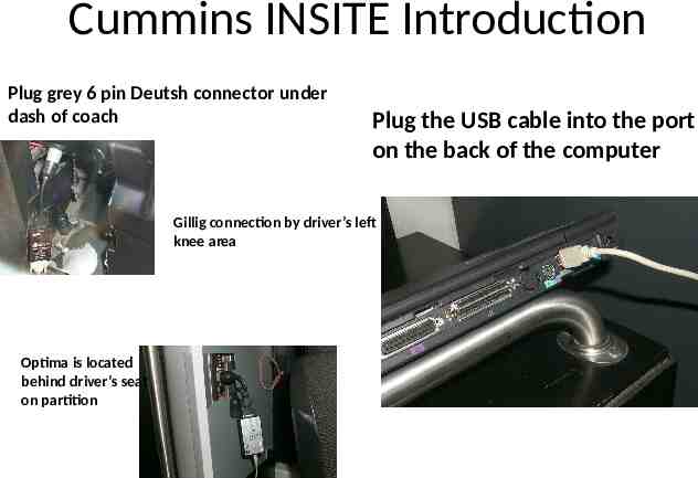
Cummins INSITE Introduction Plug grey 6 pin Deutsh connector under dash of coach Plug the USB cable into the port on the back of the computer Gillig connection by driver’s left knee area Optima is located behind driver’s seat on partition
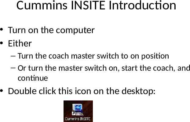
Cummins INSITE Introduction Turn on the computer Either – Turn the coach master switch to on position – Or turn the master switch on, start the coach, and continue Double click this icon on the desktop:
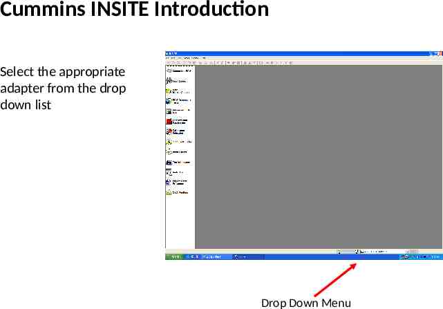
Cummins INSITE Introduction Select the appropriate adapter from the drop down list Drop Down Menu
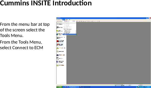
Cummins INSITE Introduction From the menu bar at top of the screen select the Tools Menu. From the Tools Menu, select Connect to ECM
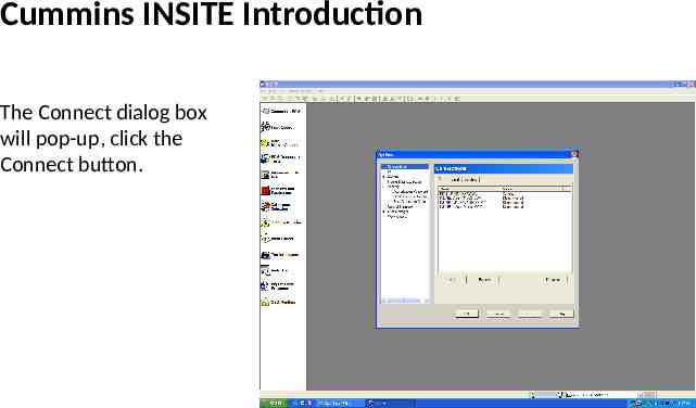
Cummins INSITE Introduction The Connect dialog box will pop-up, click the Connect button.
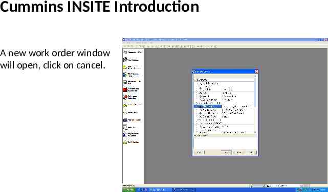
Cummins INSITE Introduction A new work order window will open, click on cancel.
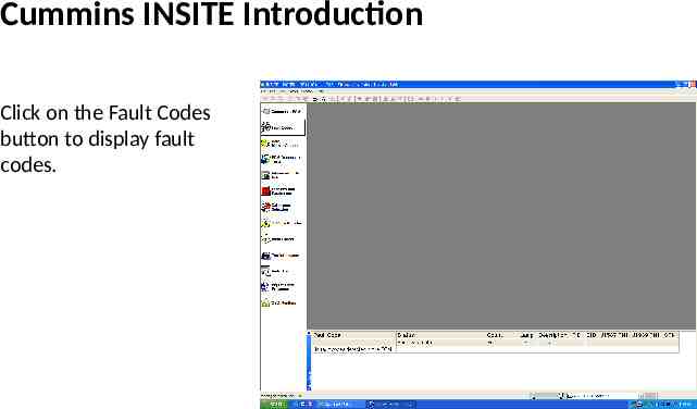
Cummins INSITE Introduction Click on the Fault Codes button to display fault codes.
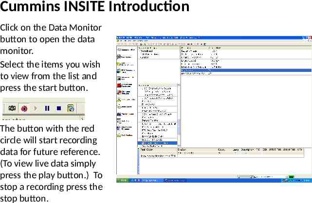
Cummins INSITE Introduction Click on the Data Monitor button to open the data monitor. Select the items you wish to view from the list and press the start button. The button with the red circle will start recording data for future reference. (To view live data simply press the play button.) To stop a recording press the stop button.
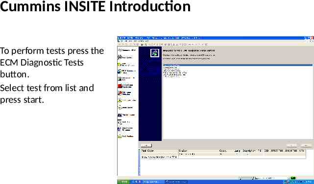
Cummins INSITE Introduction To perform tests press the ECM Diagnostic Tests button. Select test from list and press start.
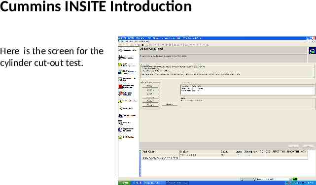
Cummins INSITE Introduction Here is the screen for the cylinder cut-out test.
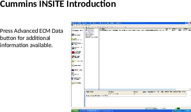
Cummins INSITE Introduction Press Advanced ECM Data button for additional information available.
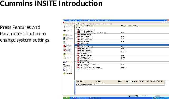
Cummins INSITE Introduction Press Features and Parameters button to change system settings.
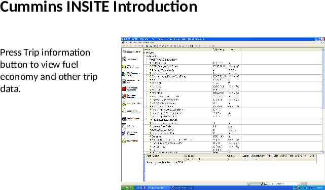
Cummins INSITE Introduction Press Trip information button to view fuel economy and other trip data.
Cummins INSITE Introduction Press Trip information button to view fuel economy and other trip data.
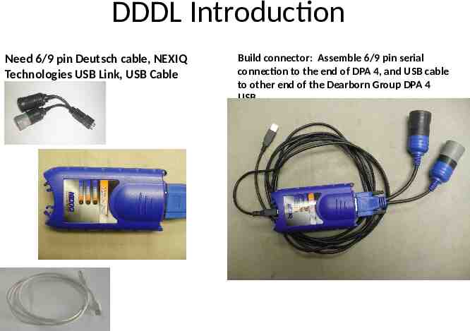
DDDL Introduction Need 6/9 pin Deutsch cable, NEXIQ Technologies USB Link, USB Cable Build connector: Assemble 6/9 pin serial connection to the end of DPA 4, and USB cable to other end of the Dearborn Group DPA 4 USB.
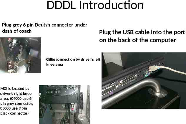
DDDL Introduction Plug grey 6 pin Deutsh connector under dash of coach Plug the USB cable into the port on the back of the computer Gillig connection by driver’s left knee area MCI is located by driver’s right knee area. (04000 use 6 pin grey connector, 05000 use 9 pin black connector)
DDDL Introduction Turn on the computer Either – Turn the coach master switch to on position – Or turn the master switch on, start the coach, and continue Double click this icon on the desktop:
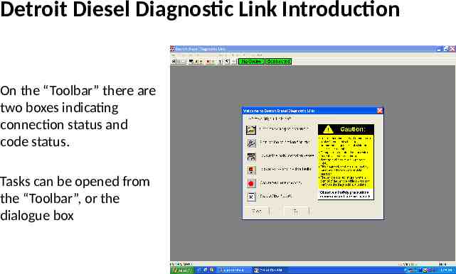
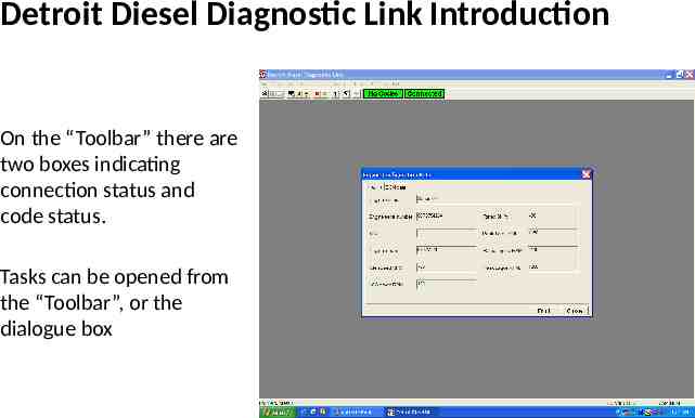
Detroit Diesel Diagnostic Link Introduction On the “Toolbar” there are two boxes indicating connection status and code status. Tasks can be opened from the “Toolbar”, or the dialogue box
Detroit Diesel Diagnostic Link Introduction On the “Toolbar” there are two boxes indicating connection status and code status. Tasks can be opened from the “Toolbar”, or the dialogue box
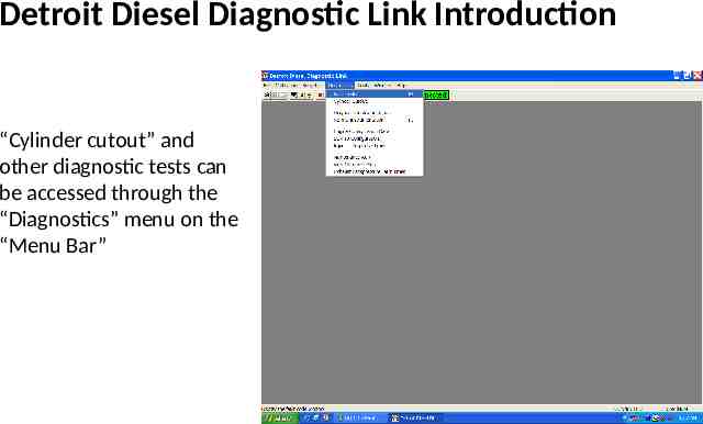
Detroit Diesel Diagnostic Link Introduction “Cylinder cutout” and other diagnostic tests can be accessed through the “Diagnostics” menu on the “Menu Bar”
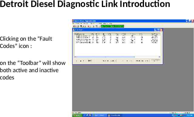
Detroit Diesel Diagnostic Link Introduction Clicking on the “Fault Codes” icon : on the “Toolbar” will show both active and inactive codes
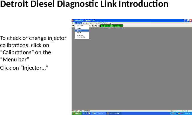
Detroit Diesel Diagnostic Link Introduction To check or change injector calibrations, click on “Calibrations” on the “Menu bar” Click on “Injector ”
EGR / Crankcase Ventilation Systems Hands-On Practice