Topics 1 Network Topology Cables and connectors Network Devices

66 Slides1.38 MB
Topics 1 Network Topology Cables and connectors Network Devices
Network Topologies LANs and WANs - Geographical coverage LANs WANs 2 A single geographical location, such as office building, school, etc Typically High speed and cheaper. Spans more than one geographical location often connecting separated LANs Slower Costly hardware, routers, dedicated leased lines and complicated implementation procedures.
Network Topologies Topology - Physical and logical network layout Common topologies: 3 Physical – actual layout of the computer cables and other network devices Logical – the way in which the network appears to the devices that use it. Bus, ring, star, mesh and wireless
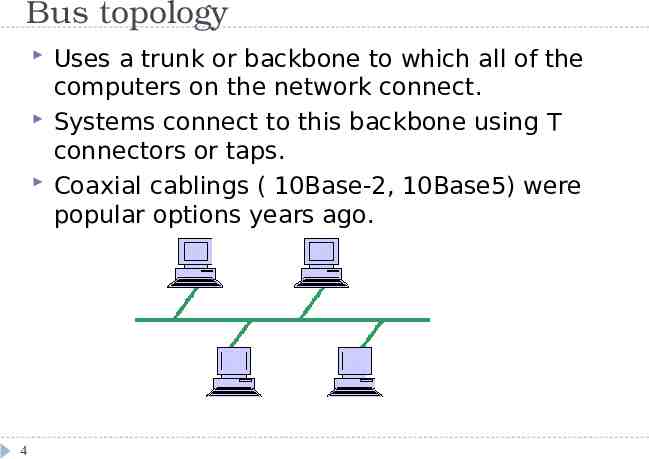
Bus topology 4 Uses a trunk or backbone to which all of the computers on the network connect. Systems connect to this backbone using T connectors or taps. Coaxial cablings ( 10Base-2, 10Base5) were popular options years ago.
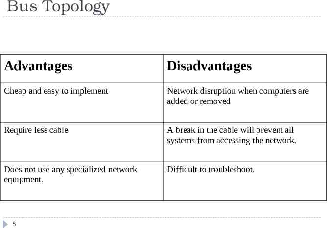
Bus Topology Advantages Disadvantages Cheap and easy to implement Network disruption when computers are added or removed Require less cable A break in the cable will prevent all systems from accessing the network. Does not use any specialized network equipment. Difficult to troubleshoot. 5
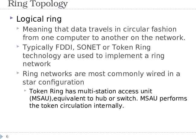
Ring Topology Logical ring Meaning that data travels in circular fashion from one computer to another on the network. Typically FDDI, SONET or Token Ring technology are used to implement a ring network Ring networks are most commonly wired in a star configuration 6 Token Ring has multi-station access unit (MSAU),equivalent to hub or switch. MSAU performs the token circulation internally.
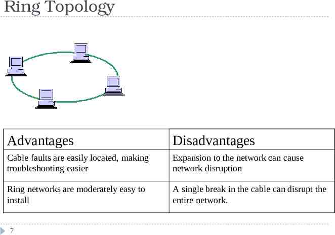
Ring Topology Advantages Disadvantages Cable faults are easily located, making troubleshooting easier Expansion to the network can cause network disruption Ring networks are moderately easy to install A single break in the cable can disrupt the entire network. 7
Star Topology 8 All computers/devices connect to a central device called hub or switch. Each device requires a single cable point-to-point connection between the device and hub. Most widely implemented Hub is the single point of failure
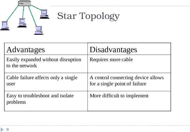
Star Topology Advantages Disadvantages Easily expanded without disruption to the network Requires more cable Cable failure affects only a single user A central connecting device allows for a single point of failure Easy to troubleshoot and isolate problems More difficult to implement 9
Mesh Topology Each computer connects to every other. High level of redundancy. Rarely used. 10 Wiring is very complicated Cabling cost is high Troubleshooting a failed cable is tricky A variation hybrid mesh – create point to point connection between specific network devices, often seen in WAN implementation.
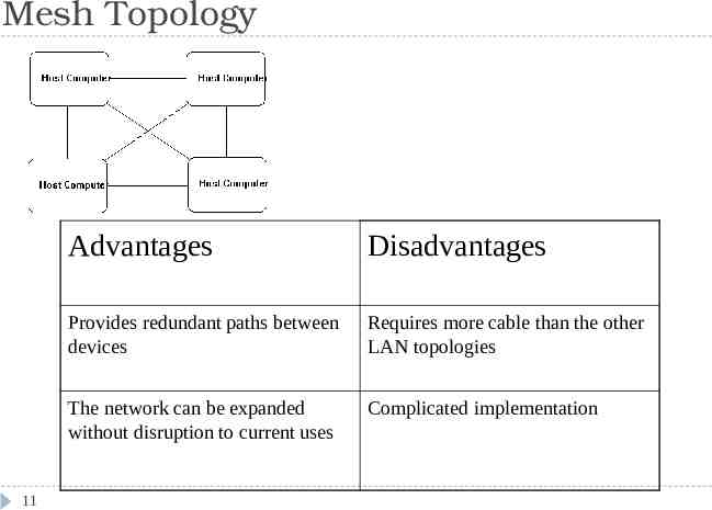
Mesh Topology 11 Advantages Disadvantages Provides redundant paths between devices Requires more cable than the other LAN topologies The network can be expanded without disruption to current uses Complicated implementation
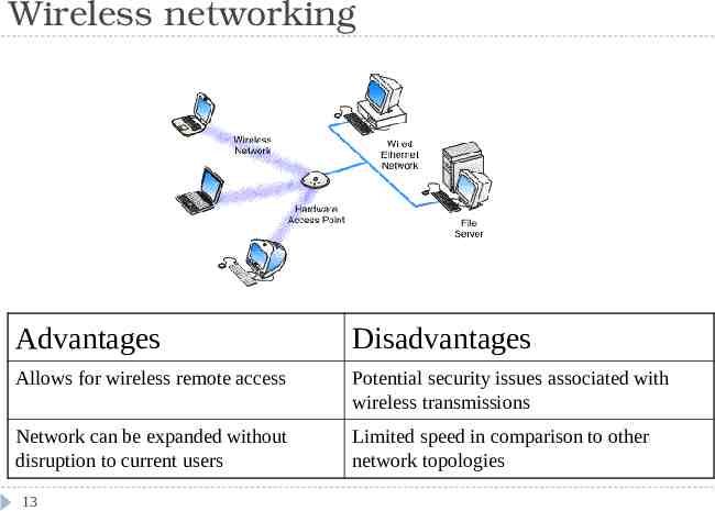
Wireless networking Do not require physical cabling Particularly useful for remote access for laptop users Eliminate cable faults and cable breaks. Signal interference and security issue. 12
Wireless networking Advantages Disadvantages Allows for wireless remote access Potential security issues associated with wireless transmissions Network can be expanded without disruption to current users Limited speed in comparison to other network topologies 13
Cabling and Connectors General media considerations Broadband versus baseband Baseband transmissions use digital signaling and Time Division Multiplexing (TDM) Broadband transmissions use analog and Frequency Division Multiplexing(FDM) Dialog modes: Simplex, half duplex and full duplex
Cabling and Connectors Media interference Electromagnetic interference (EMI) and cross talk Network media vary in their resistance to the effect of EMC. Attenuation Resistance :Coaxial cable UTP, STP UTP, Fiber all Maximum distance Repeaters Attenuation-related problems require a network analyzer to detect Bandwidth 15 UTP is susceptible and fiber is resistant Transmission capacity of a media Data throughput is measured in bits per second(bps), Mbps, and Gbps For today’s application-intensive networks, Old 10Mbps is not enough, 100Mbps is very common and 1000Mbps is used too.
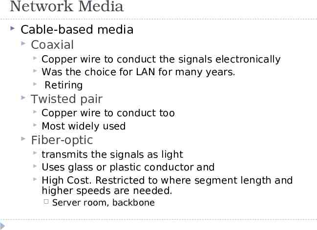
Network Media Cable-based media Coaxial Twisted pair Copper wire to conduct the signals electronically Was the choice for LAN for many years. Retiring Copper wire to conduct too Most widely used Fiber-optic transmits the signals as light Uses glass or plastic conductor and High Cost. Restricted to where segment length and higher speeds are needed. Server room, backbone
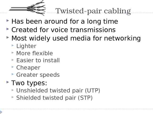
Twisted-pair cabling Has been around for a long time Created for voice transmissions Most widely used media for networking Lighter More flexible Easier to install Cheaper Greater speeds Two types: Unshielded twisted pair (UTP) Shielded twisted pair (STP)
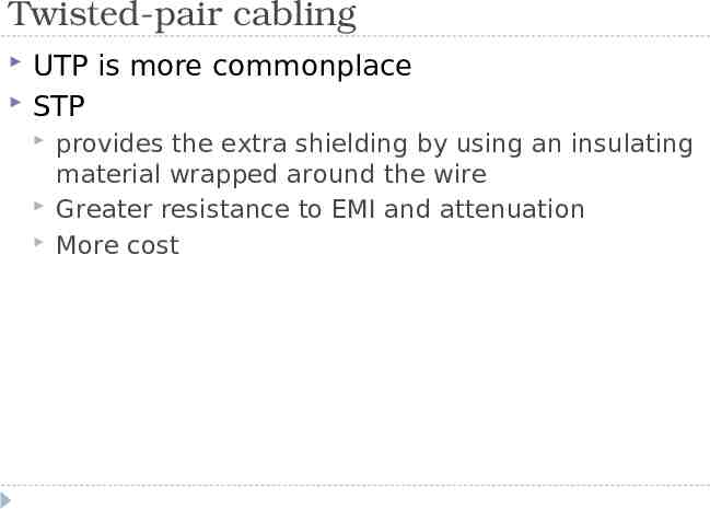
Twisted-pair cabling UTP is more commonplace STP provides the extra shielding by using an insulating material wrapped around the wire Greater resistance to EMI and attenuation More cost
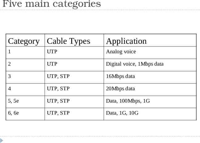
Five main categories Category Cable Types Application 1 UTP Analog voice 2 UTP Digital voice, 1Mbps data 3 UTP, STP 16Mbps data 4 UTP, STP 20Mbps data 5, 5e UTP, STP Data, 100Mbps, 1G 6, 6e UTP, STP Data, 1G, 10G
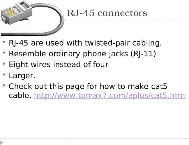
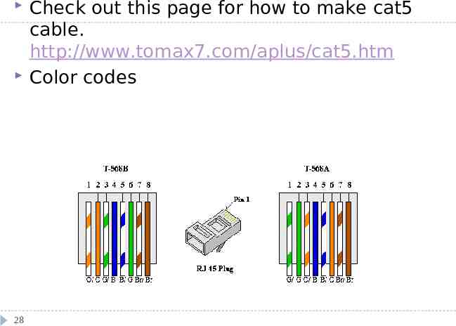
RJ-45 connectors RJ-45 are used with twisted-pair cabling. Resemble ordinary phone jacks (RJ-11) Eight wires instead of four Larger. Check out this page for how to make cat5 cable. http://www.tomax7.com/aplus/cat5.htm
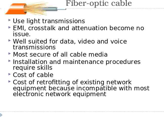
Fiber-optic cable Use light transmissions EMI, crosstalk and attenuation become no issue. Well suited for data, video and voice transmissions Most secure of all cable media Installation and maintenance procedures require skills Cost of cable Cost of retrofitting of existing network equipment because incompatible with most electronic network equipment
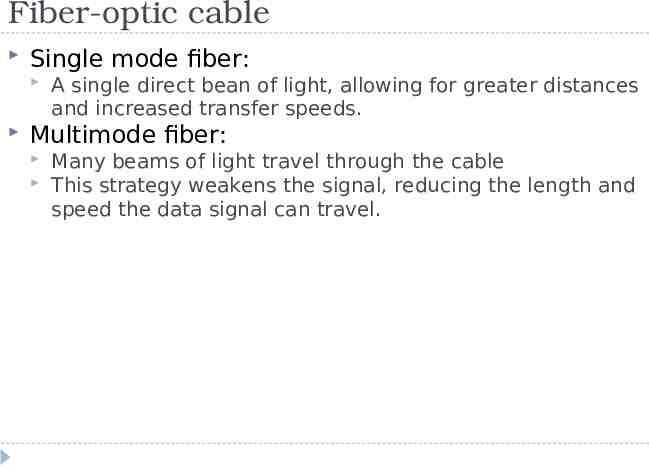
Fiber-optic cable Single mode fiber: A single direct bean of light, allowing for greater distances and increased transfer speeds. Multimode fiber: Many beams of light travel through the cable This strategy weakens the signal, reducing the length and speed the data signal can travel.
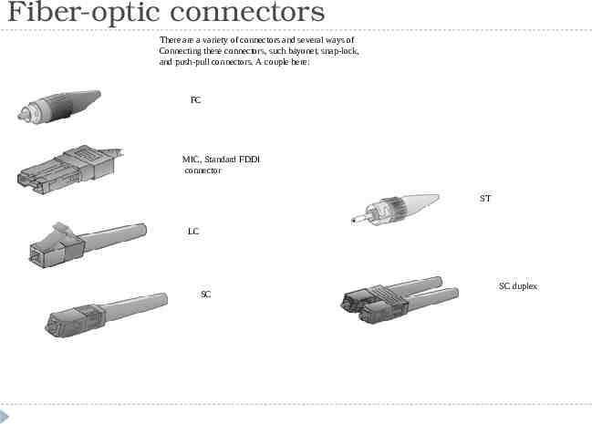
Fiber-optic connectors There are a variety of connectors and several ways of Connecting these connectors, such bayonet, snap-lock, and push-pull connectors. A couple here: FC MIC, Standard FDDI connector ST LC SC SC duplex
Wireless media Three types: Radio wave Infrared Microwave Speeds of wireless solutions don’t keep pace with cable solutions Installation and maintenance are far more complicated and costly. Some solutions require line-of-sight, such as infrared and microwave.
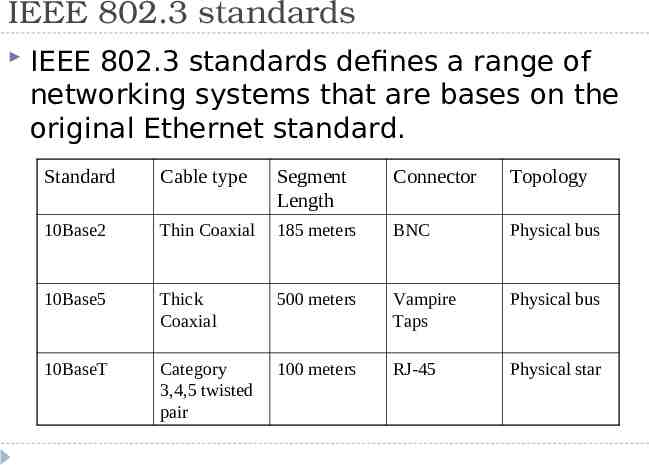
IEEE 802.3 standards IEEE 802.3 standards defines a range of networking systems that are bases on the original Ethernet standard. Standard Cable type Segment Length Connector Topology 10Base2 Thin Coaxial 185 meters BNC Physical bus 10Base5 Thick Coaxial 500 meters Vampire Taps Physical bus 10BaseT Category 3,4,5 twisted pair 100 meters RJ-45 Physical star
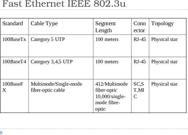
Fast Ethernet IEEE 802.3u Standard Cable Type Segment Length Conn Topology ector 100BaseTx Category 5 UTP 100 meters RJ-45 Physical star 100BaseT4 Category 3,4,5 UTP 100 meters RJ-45 Physical star 100BaseF X 412/Multimode fiber-optic 10,000/singlemode fiberoptic SC,S T,MI C Multimode/Single-mode fiber-optic cable Physical star
Gigabit Ethernet 802.3z and 802.3ab Standard Cable Type Segment length Connector 1000BaseLX Multimode/ singlemode fiber 550/multimode 5000/single-mode Fiber connectors 1000BaseSX Multimode fiber 550 meters using 50 Micron multimode fiber Fiber connectors 1000BaseCX STP twisted pair 25 meters 9-pin shielded connector, 8-pin fiber channel type 2 connector 1000BaseT Category 5 UTP 100 meters RJ-45
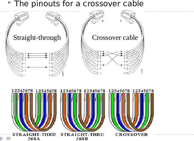
28 Check out this page for how to make cat5 cable. http://www.tomax7.com/aplus/cat5.htm Color codes
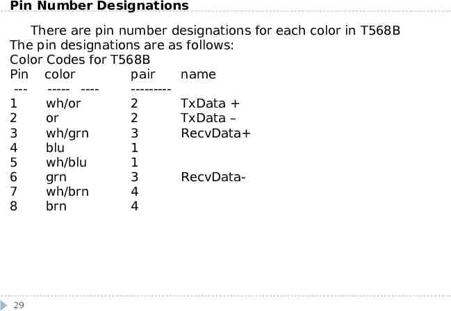
Pin Number Designations There are pin number designations for each color in T568B The pin designations are as follows: Color Codes for T568B Pin color pair name ------- -----------1 wh/or 2 TxData 2 or 2 TxData – 3 wh/grn 3 RecvData 4 blu 1 5 wh/blu 1 6 grn 3 RecvData7 wh/brn 4 8 brn 4 29
The pinouts for a crossover cable Straight-through 30 Crossover cable
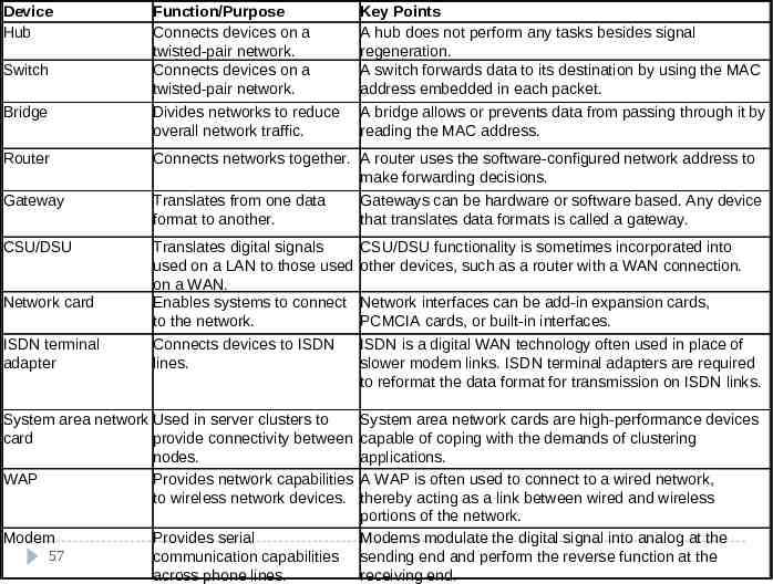
Networking Devices 31 repeaters Hubs Switches Bridges Routes Gateways Network Interface Cards (NICs) Wireless access points Modems
Hubs The bottom of the networking food chain Connect device and create larger networks Small hubs 5-8 ports (workgroup hubs) Some hubs have more ports, up to 32 normally Direct data packets to all devices connected to the hub - shared bandwidth animation Scalability, Collision, inefficient 32
Bridges Divide larger networks into smaller sections Check MAC address, forward or block the data Learning bridge builds list of MAC address by watching the traffic on the network. Two issues to consider: Placement 80/20 rule Bridging loops IEEE 802.1d Spanning tree protocol Types of bridges 33 Transparent bridge Source route bridge Translational bridge
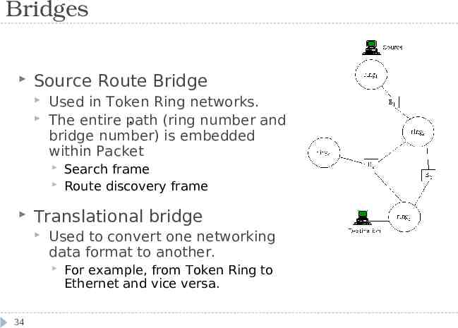
Bridges Source Route Bridge Used in Token Ring networks. . The entire path (ring number and bridge number) is embedded within Packet Translational bridge Used to convert one networking data format to another. 34 Search frame Route discovery frame For example, from Token Ring to Ethernet and vice versa.
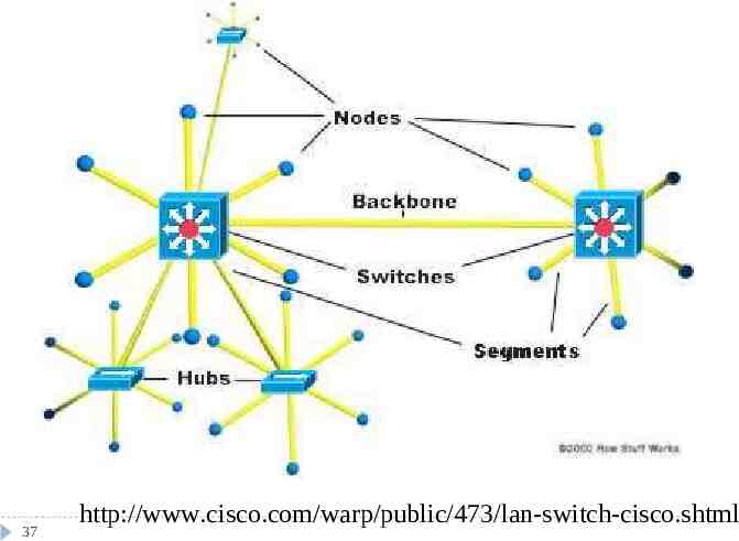
Switches Like hub, connectivity points of Ethernet network Forward only to the port that connects to the destination device knows MAC address Match the MAC address in the data it receives. Fully switched network, a dedicated segment for each device is connected to switch. Expensive. 35
Switches Allow full duplex Ethernet Nodes only communicate with switch, never directly to each other Use twisted pair or fiber optic cabling, using separate conductors for sending and receiving data. collision pair is used to transmit data It was half duplex before – one device can transmit at one given time, double the capacity, 100Mbps become 200Mbps Most LAN are mixed with hubs and switches. 36
37 http://www.cisco.com/warp/public/473/lan-switch-cisco.shtml
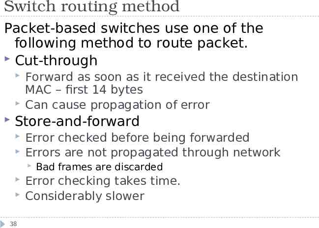
Switch routing method Packet-based switches use one of the following method to route packet. Cut-through Forward as soon as it received the destination MAC – first 14 bytes Can cause propagation of error Store-and-forward Error checked before being forwarded Errors are not propagated through network 38 Bad frames are discarded Error checking takes time. Considerably slower
Switch Routing Method FragmentFree 39 Take the advantage of both. Check errors by reading the first 64byte of packets where collision most likely happens Offer near cut-through switching performance
Switch physical design LAN switches vary in their physical design Shared-memory Matrix Internal grid with input port and output crossing each other First check MAC, then switch makes a connection where two ports (input/output) intersect Bus-architecture 40 Common buffer for all ports Common-bus Dedicated buffer for each port and a circuit to control the bus access
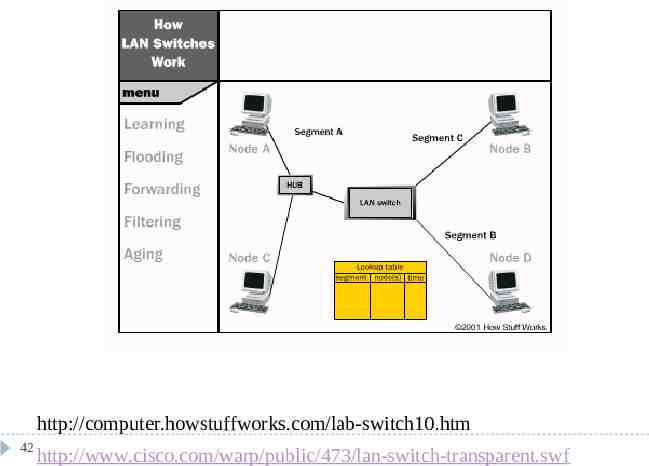
Switch and Transparent Bridging Most LAN switches use transparent bridging to create address lookup tables Transparent bridging is a technology that allows a switch to learn everything it needs to know about the location of nodes on the network within the network administrator having to do anything. Has five parts: 41 Learning Flooding Filtering Forwarding Aging
http://computer.howstuffworks.com/lab-switch10.htm 42 http://www.cisco.com/warp/public/473/lan-switch-transparent.swf
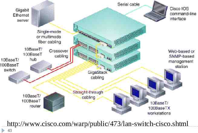
http://www.cisco.com/warp/public/473/lan-switch-cisco.shtml 43
Hub and switch cabling To create larger networks, connect hubs and switches using Standard port - Medium Dependent InterfaceCrossed (MDI-X) To see each other as an extension, no signal to be crossed Using crossover cable between two MDI-X ports 44 Two wires are crossed internally Medium Dependent Interface (MDI) Standard port with special cable Special ports with a standard cable To uncross the internal crossing
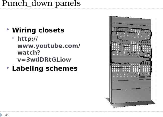
Punch down panels Wiring closets 45 http:// www.youtube.com/ watch? v 3wdDRtGLiow Labeling schemes
Routers Create larger networks by joining two networks segments. Dedicated hardware device or computer systems with more than one network interface and routing software. Routing table Static routing Dynamic routing 46 Use special routing protocols to pass info to other routers. Distance Vector Routing (RIP) Link state routing (OSPF)
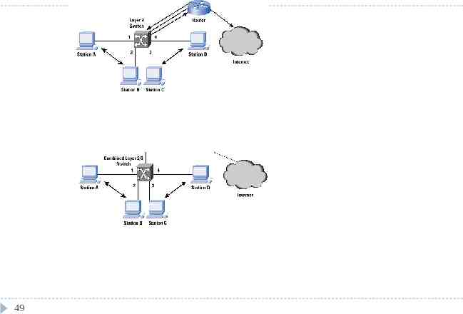
Switch and Router Different with router – Typically switch works on lower level (Data link Layer) while Router works in higher level (Network Layer) – Algorithms for router and switch about how to forward packers are different For example, switch will forward broadcast, so does hub, not router- the address has to be specific. 47
Routers and Layer 3 Switch While most switches operate at the Data link layer(layer2), some incorporate features of a router and operate at the network layer (layer3). Layer 3 switches are faster because they are build on “switching” hardware a router is needed for VLANS communication Why not build a router in the switch itself and do the forwarding in hardware EX: IP forwarding – all in hardware 48 Route lookup Decrement the Time to Live (TTL) Recalculation the checksum Forward the frame the frame to correct output port
49
Gateways Any device that translate one data format to another is called a gateway. Router Bridge Software Gateway and default gateway 50
CSU/DSU Channel Server Unit/Digital Service Unit ( CSU/DSU) or Data Service Unit Convert digital format on LAN into signal used on WAN 51 Sit between LAN and access point provided by telecom company Many routers have CSU/DSU functionality
Wireless access points Devices that provide connectivity between wireless LAN devices and in most cases a wired network. Antennae Convert signal from radio wave or other to that used on the LANs. 52
Modems Modulator/Demodulator, convert digital signal generated by computer into analog signals that can travel over conventional phone line. Connect to ISP Dialing up to a LAN Internal add-in expansion cards or external devices connect to serial or USB port PCMCIA cards for laptop Speed Modem itself Speed of the Universal Asynchronous Receiver/Transmitter (UART) chip, 53 UART 16950 has the speed of 921,600kbp
Network cards Called Network Interface Cards (NIC) Attached to external port PC card Internal Network card System bus compatibility System Resources – device conflict Media compatibility Peripheral Component Interconnect (PCI) Industry Standard Architecture (ISA) Twisted pair, coaxial or fiber-optic connection? Driver 54
ISDN adapters Integrated Services Digital Networking (ISDN) is a remote access and WAN technology that can be used in place of a Plain old telephone systems dial-up link Greater speeds than modem, pick up and drop the line considerable faster. Require ISDN terminal adapter 55 Although digital signal, different format with the those used on LAN. Create multiple communication channels on a single line.
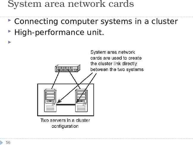
System area network cards 56 Connecting computer systems in a cluster High-performance unit.
Device Hub Function/Purpose Connects devices on a twisted-pair network. Connects devices on a twisted-pair network. Key Points A hub does not perform any tasks besides signal regeneration. A switch forwards data to its destination by using the MAC address embedded in each packet. Bridge Divides networks to reduce overall network traffic. A bridge allows or prevents data from passing through it by reading the MAC address. Router Connects networks together. A router uses the software-configured network address to make forwarding decisions. Gateway Translates from one data format to another. Gateways can be hardware or software based. Any device that translates data formats is called a gateway. CSU/DSU Translates digital signals used on a LAN to those used on a WAN. Enables systems to connect to the network. CSU/DSU functionality is sometimes incorporated into other devices, such as a router with a WAN connection. Connects devices to ISDN lines. ISDN is a digital WAN technology often used in place of slower modem links. ISDN terminal adapters are required to reformat the data format for transmission on ISDN links. Switch Network card ISDN terminal adapter System area network Used in server clusters to card provide connectivity between nodes. WAP Provides network capabilities to wireless network devices. Modem 57 Provides serial communication capabilities across phone lines. Network interfaces can be add-in expansion cards, PCMCIA cards, or built-in interfaces. System area network cards are high-performance devices capable of coping with the demands of clustering applications. A WAP is often used to connect to a wired network, thereby acting as a link between wired and wireless portions of the network. Modems modulate the digital signal into analog at the sending end and perform the reverse function at the receiving end.
MAC addresses Unique 6-byte address burned info network interface, expressed in hexadecimal No matter which protocol is used, MAC address is the means by which the network interface is identified on the network. IEEE managing MAC address assignment IEEE has a system Identifying the manufacturer by looking at the MAC address Discover MAC address, depend on the OS Ifconfig /all on WINDOWs NT/2000 Ifconfig –a on Linux/UNIX 58
Watch the Intel Gigabit demo. 59 http://www.intel.com/network/connectivity/resourc es/demos/gigabit/base.swf
IEEE and Networking standards Institute of Electrical and Electronic Engineers (IEEE) developed a series of networking standards 60 Networking technologies developed by manufacturers are Compatible Cabling, networking devices and protocols are all interchangeable under the banner of a specific IEEE
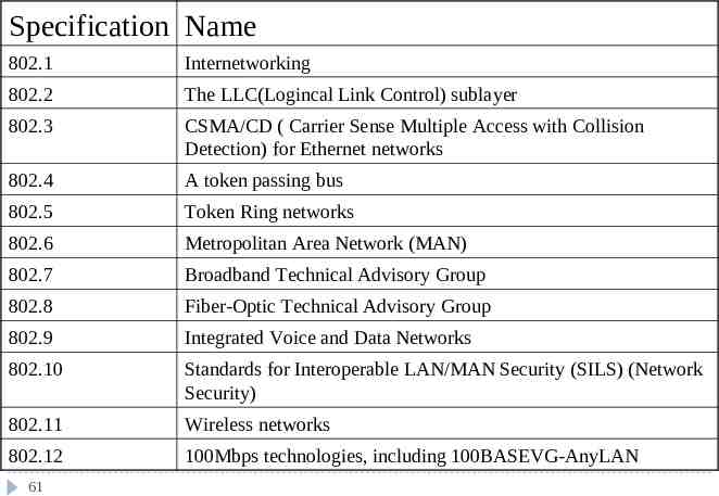
Specification Name 802.1 Internetworking 802.2 The LLC(Logincal Link Control) sublayer 802.3 CSMA/CD ( Carrier Sense Multiple Access with Collision Detection) for Ethernet networks 802.4 A token passing bus 802.5 Token Ring networks 802.6 Metropolitan Area Network (MAN) 802.7 Broadband Technical Advisory Group 802.8 Fiber-Optic Technical Advisory Group 802.9 Integrated Voice and Data Networks 802.10 Standards for Interoperable LAN/MAN Security (SILS) (Network Security) 802.11 Wireless networks 802.12 100Mbps technologies, including 100BASEVG-AnyLAN 61
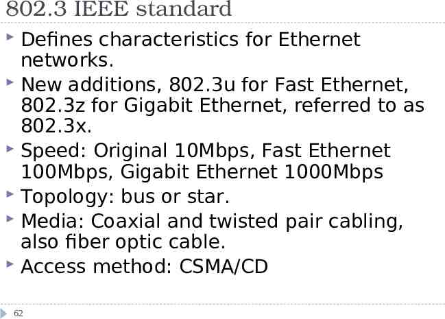
802.3 IEEE standard Defines characteristics for Ethernet networks. New additions, 802.3u for Fast Ethernet, 802.3z for Gigabit Ethernet, referred to as 802.3x. Speed: Original 10Mbps, Fast Ethernet 100Mbps, Gigabit Ethernet 1000Mbps Topology: bus or star. Media: Coaxial and twisted pair cabling, also fiber optic cable. Access method: CSMA/CD 62
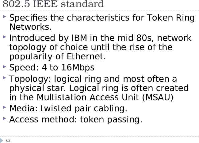
802.5 IEEE standard Specifies the characteristics for Token Ring Networks. Introduced by IBM in the mid 80s, network topology of choice until the rise of the popularity of Ethernet. Speed: 4 to 16Mbps Topology: logical ring and most often a physical star. Logical ring is often created in the Multistation Access Unit (MSAU) Media: twisted pair cabling. Access method: token passing. 63
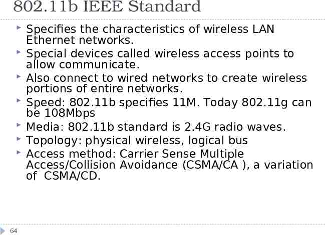
802.11b IEEE Standard 64 Specifies the characteristics of wireless LAN Ethernet networks. Special devices called wireless access points to allow communicate. Also connect to wired networks to create wireless portions of entire networks. Speed: 802.11b specifies 11M. Today 802.11g can be 108Mbps Media: 802.11b standard is 2.4G radio waves. Topology: physical wireless, logical bus Access method: Carrier Sense Multiple Access/Collision Avoidance (CSMA/CA ), a variation of CSMA/CD.
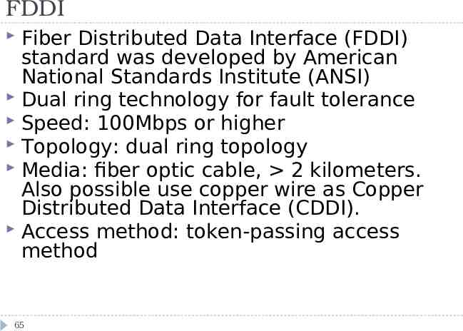
FDDI Fiber Distributed Data Interface (FDDI) standard was developed by American National Standards Institute (ANSI) Dual ring technology for fault tolerance Speed: 100Mbps or higher Topology: dual ring topology Media: fiber optic cable, 2 kilometers. Also possible use copper wire as Copper Distributed Data Interface (CDDI). Access method: token-passing access method 65
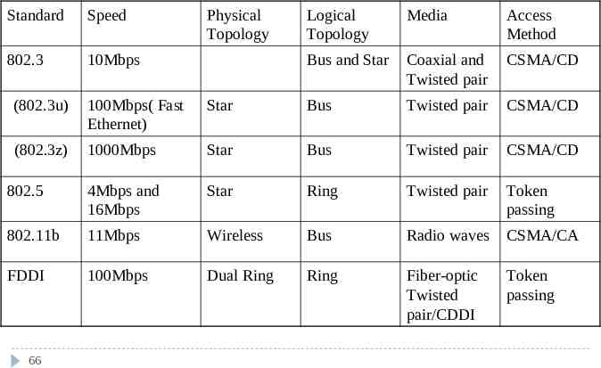
Standard Speed 802.3 10Mbps Physical Topology Logical Topology Media Access Method Bus and Star Coaxial and Twisted pair CSMA/CD (802.3u) 100Mbps( Fast Ethernet) Star Bus Twisted pair CSMA/CD (802.3z) 1000Mbps Star Bus Twisted pair CSMA/CD 802.5 4Mbps and 16Mbps Star Ring Twisted pair Token passing 802.11b 11Mbps Wireless Bus Radio waves CSMA/CA FDDI 100Mbps Dual Ring Ring Fiber-optic Twisted pair/CDDI Token passing 66