The Structured Specification

26 Slides101.50 KB
The Structured Specification
Why a Structured Specification? System analyst communicates the user requirements to the designer with a document called the functional specification which. – may be full of computer terms the user doesn’t understand – may impose unnecessary constraints on designer Result is a specification which – involves a lot of reading and is difficult to follow – improperly records the users’ needs
Qualities of Structured Specification Graphic and concise – A picture is worth a thousand words – More consistent and takes less time to understand Top-down partitioned – Don’t bite off more than you can chew Non-redundant – Compact and consistent Essential – Focus on what system will do, save how for later
Components of Structured Specification Data flow diagram (DFD) Data dictionary Tools to specify processes – Structured English – Decision tree/table Information model
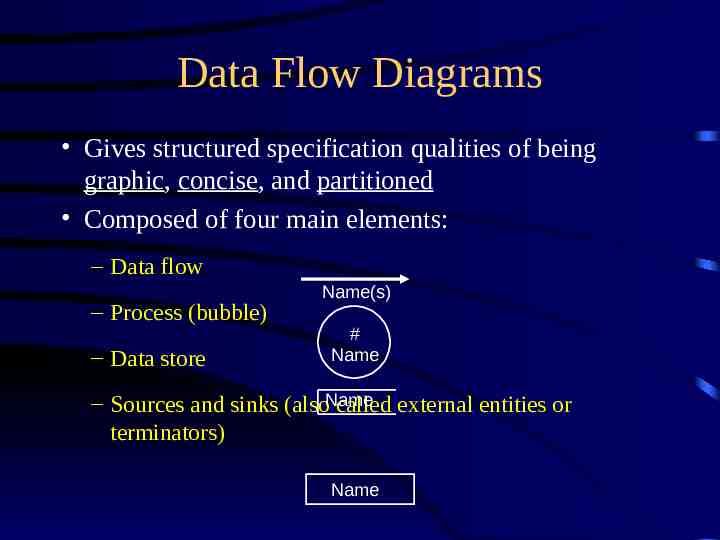
Data Flow Diagrams Gives structured specification qualities of being graphic, concise, and partitioned Composed of four main elements: – Data flow – Process (bubble) – Data store Name(s) # Name – Sources and sinks (alsoName called external entities or terminators) Name
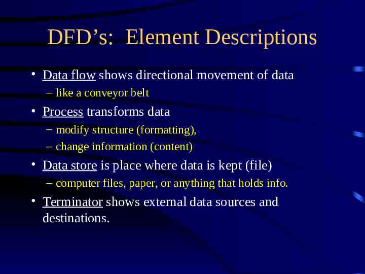
DFD’s: Element Descriptions Data flow shows directional movement of data – like a conveyor belt Process transforms data – modify structure (formatting), – change information (content) Data store is place where data is kept (file) – computer files, paper, or anything that holds info. Terminator shows external data sources and destinations.
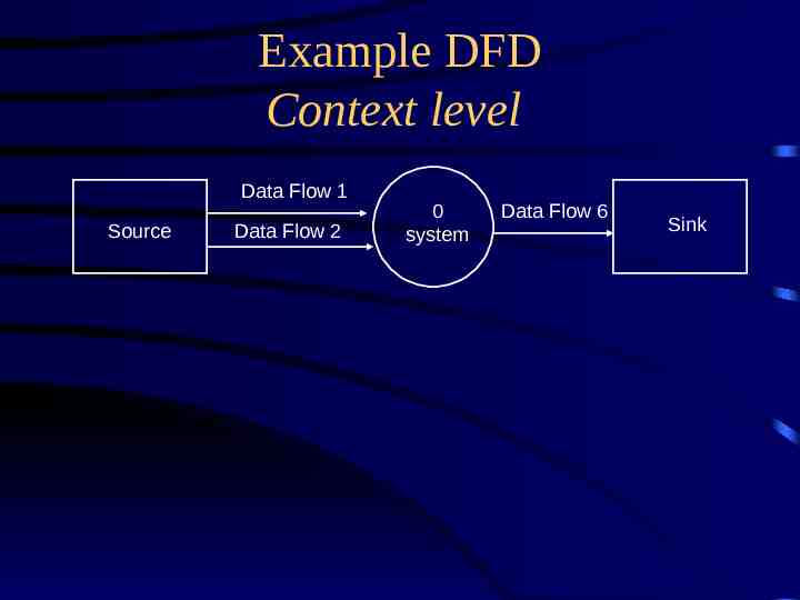
Example DFD Context level Data Flow 1 Source Data Flow 2 0 system Data Flow 6 Sink
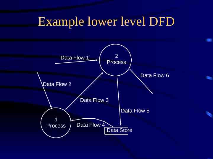
Example lower level DFD Data Flow 1 2 Process Data Flow 6 Data Flow 2 Data Flow 3 Data Flow 5 1 Process Data Flow 4 Data Store
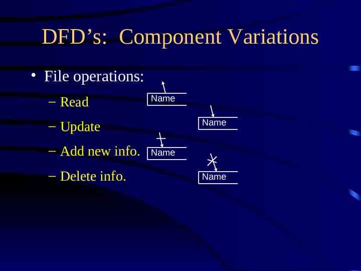
DFD’s: Component Variations File operations: – Read Name Name – Update – Add new info. – Delete info. Name Name
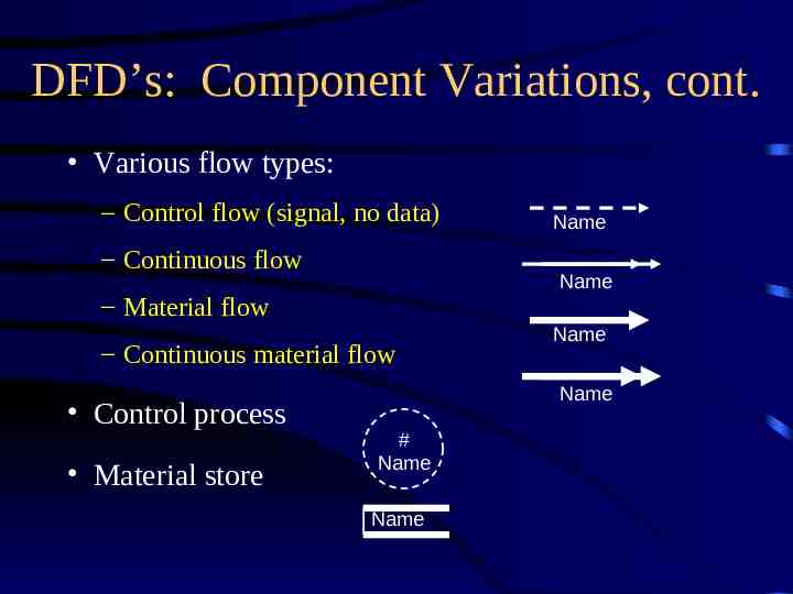
DFD’s: Component Variations, cont. Various flow types: – Control flow (signal, no data) – Continuous flow Name – Material flow – Continuous material flow Control process Material store Name Name Name # Name Name
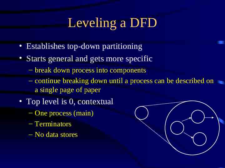
Leveling a DFD Establishes top-down partitioning Starts general and gets more specific – break down process into components – continue breaking down until a process can be described on a single page of paper Top level is 0, contextual – One process (main) – Terminators – No data stores
Leveling a DFD, cont. No more than 7 or 8 processes on a level Data flows to and from a bubble must all be shown on the diagram for that bubble (the next level down) Don’t show error flows on parent level Show terminators on top level Don’t show data stores on top level
Guidelines for Drawing DFD’s Give elements precise names Make sure everyone agrees with a diagram before developing more detailed diagrams Show errors/rejects as short stubs Don’t flowchart (loop back for more data) Ignore how files are accessed Diagram using an iterative process -- start with something, then improve it Show data stores only when needed
Implementation-dependent vs. Essential DFD’s Implementation-dependent looks at way in which business happens to be done Helps uncover essential functions and data Shows actual names of people, forms, etc. Allows for initial feel of how business is run Not good to develop a system from -- must still make an essential DFD
The Data Dictionary Contains definitions of all data mentioned – in the DFD – in a process specification – in the data dictionary itself Composite data is defined in terms of components Elementary data is defined in terms of meanings of each value it can assume May have other info (size, response time, etc)
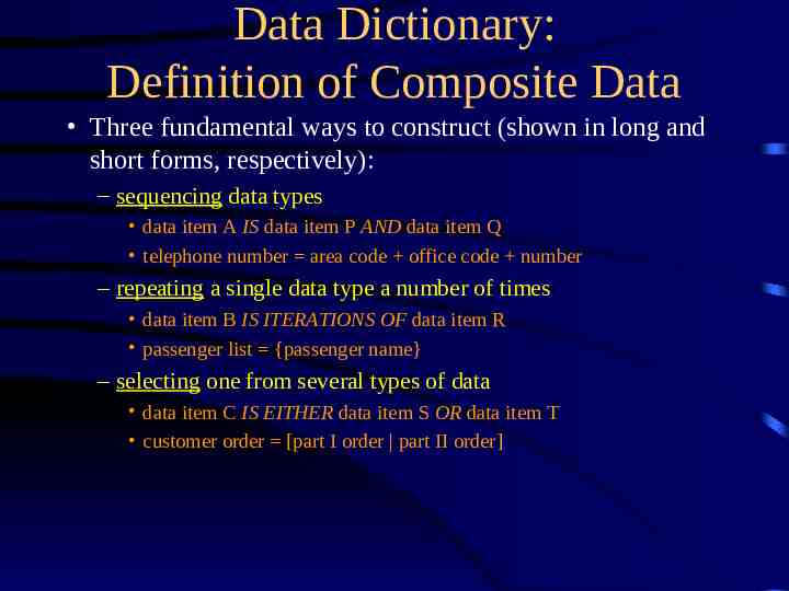
Data Dictionary: Definition of Composite Data Three fundamental ways to construct (shown in long and short forms, respectively): – sequencing data types data item A IS data item P AND data item Q telephone number area code office code number – repeating a single data type a number of times data item B IS ITERATIONS OF data item R passenger list {passenger name} – selecting one from several types of data data item C IS EITHER data item S OR data item T customer order [part I order part II order]
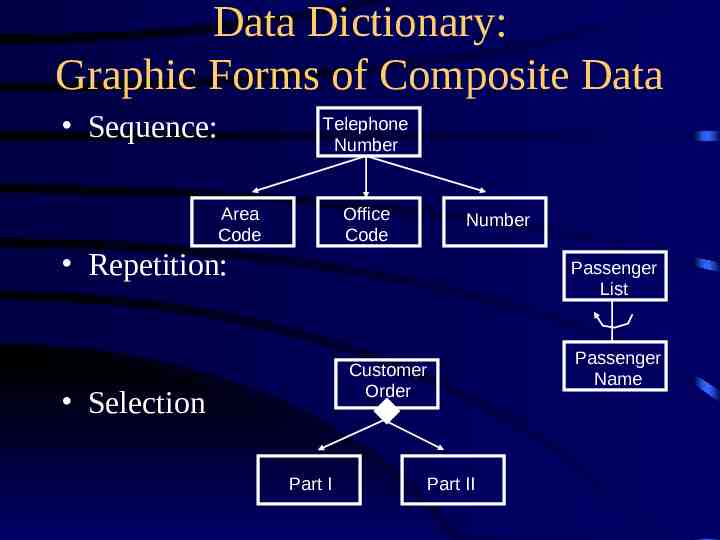
Data Dictionary: Graphic Forms of Composite Data Sequence: Telephone Number Area Code Office Code Repetition: Number Passenger List Customer Order Selection Part I Part II Passenger Name
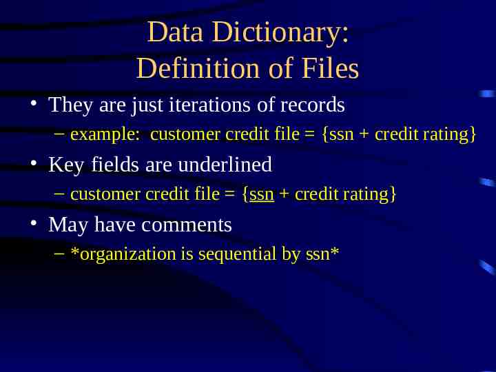
Data Dictionary: Definition of Files They are just iterations of records – example: customer credit file {ssn credit rating} Key fields are underlined – customer credit file {ssn credit rating} May have comments – *organization is sequential by ssn*
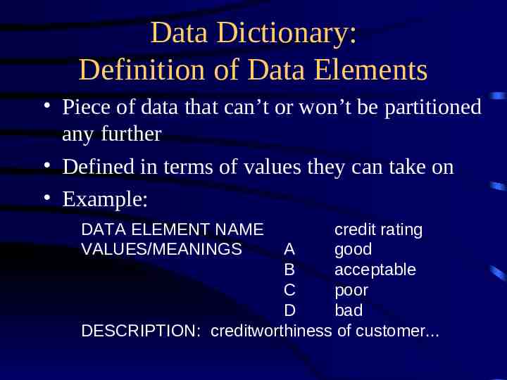
Data Dictionary: Definition of Data Elements Piece of data that can’t or won’t be partitioned any further Defined in terms of values they can take on Example: DATA ELEMENT NAME VALUES/MEANINGS credit rating A good B acceptable C poor D bad DESCRIPTION: creditworthiness of customer.
Specification Tools: Goals Provide one mini-spec for each functional primitive in the DFD State how data is transformed State what the transformation of the data is Minimize redundancy Keep simple and standard
Specification Tools: Structured English Vocabulary – imperative English verbs – terms from data dictionary – reserved words to denote logic Syntax – – – – simple sentences closed-end decisions closed-end repetitions combinations of the above
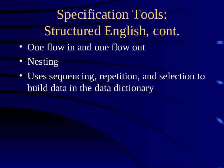
Specification Tools: Structured English, cont. One flow in and one flow out Nesting Uses sequencing, repetition, and selection to build data in the data dictionary
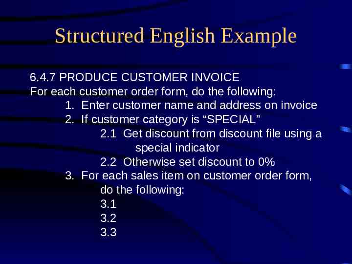
Structured English Example 6.4.7 PRODUCE CUSTOMER INVOICE For each customer order form, do the following: 1. Enter customer name and address on invoice 2. If customer category is “SPECIAL” 2.1 Get discount from discount file using a special indicator 2.2 Otherwise set discount to 0% 3. For each sales item on customer order form, do the following: 3.1 3.2 3.3
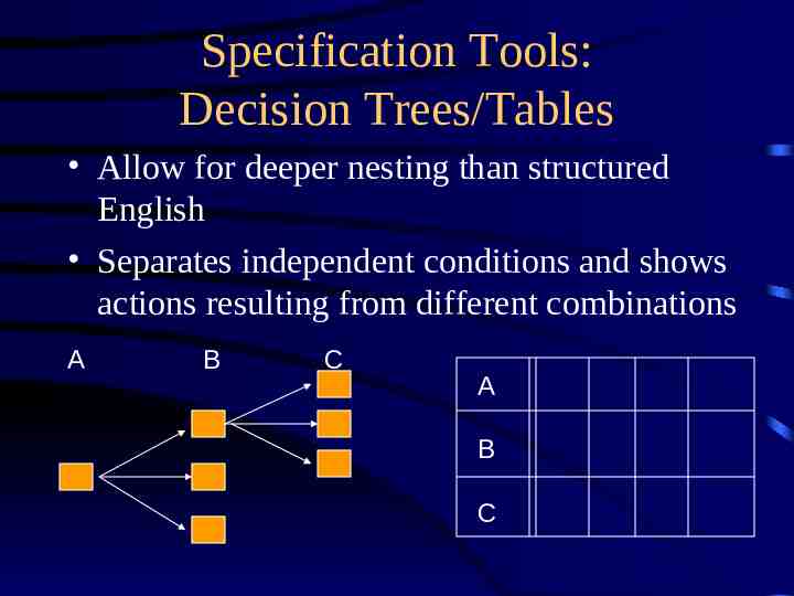
Specification Tools: Decision Trees/Tables Allow for deeper nesting than structured English Separates independent conditions and shows actions resulting from different combinations A B C A B C
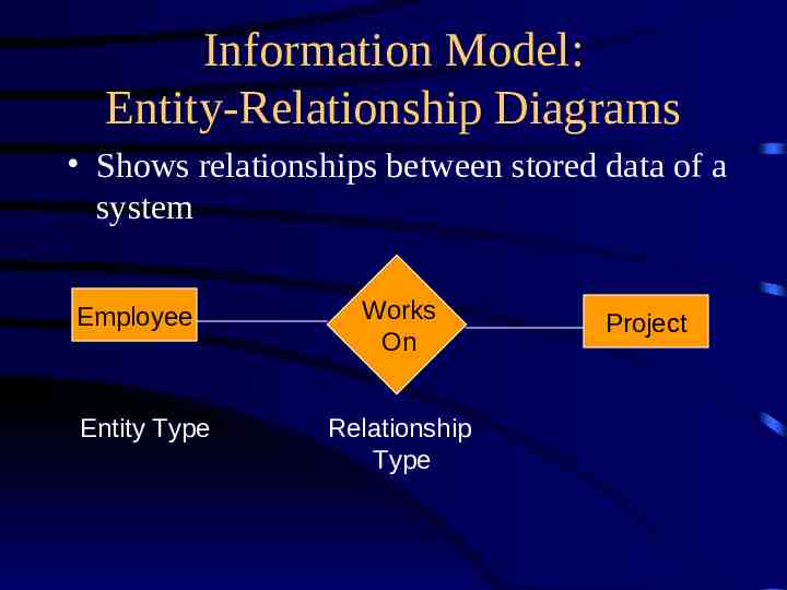
Information Model: Entity-Relationship Diagrams Shows relationships between stored data of a system Employee Entity Type Works On Relationship Type Project
Putting It All Together Leveled data flow diagrams, with context at top and functional primitives at bottom Mini-spec for each functional primitive in one of the specification forms Data dictionary Information model showing entity and relationship types, their definitions, and definitions of their attributes