Technology Integration: RSerPool & Server Load-balancing Curt Kersey,


43 Slides166.50 KB
Technology Integration: RSerPool & Server Load-balancing Curt Kersey, Cisco Systems Aron Silverton, Motorola Labs
Contents Motivation Background: Unified approach: Server Load-balancing Server Feedback RSerPool Description Sample Flows Work Items
Assumptions / Terminology All load-balancing examples will use TCP/IP as the transport protocol. This could easily be any other protocol (e.g., SCTP). SLB Server Load-Balancer. Virtual Server Virtual instance of application running on SLB device. Real Server physical machine with application instances.
Motivation Highly redundant SLB. More accurate server pooling.
Server Load-balancing
What does a SLB do? Gets user to needed resource: Server must be available User’s “session” must not be broken In order to do work, SLB must: If user must get to same resource over and over, the SLB device must ensure that happens (ie, session persistence) Know servers – IP/port, availability Understand details of some protocols (e.g., FTP, SIP, etc) Network Address Translation, NAT: Packets are re-written as they pass through SLB device.
Why to Load-balance? Scale applications / services Ease of administration / maintenance Easily and transparently remove physical servers from rotation in order to perform any type of maintenance on that server. Resource sharing Can run multiple instances of an application / service on a server; could be running on a different port for each instance; can load-balance to different port based on data analyzed.
Load-Balancing Algorithms Most predominant: least connections: server with fewest number of flows gets the new flow request. weighted least connections: associate a weight / strength for each server and distribute load across server farm based on the weights of all servers in the farm. round robin: round robin thru the servers in server farm. weighted round robin: give each server ‘weight’ number of flows in a row; weight is set just like it is in weighted least flows. There are other algorithms that look at or try to predict server load in determining the load of the real server.
How SLB Devices Make Decisions The SLB device can make its load-balancing decisions based on several factors. Some of these factors can be obtained from the packet headers (i.e., IP address, port numbers, etc.). Other factors are obtained by looking at the data beyond the network headers. Examples: HTTP Cookies HTTP URLs SSL Client certificate The decisions can be based strictly on flow counts or they can be based on knowledge of application. For some protocols, like FTP, you have to have knowledge of protocol to correctly load-balance (i.e., control and data connection must go to same physical server).
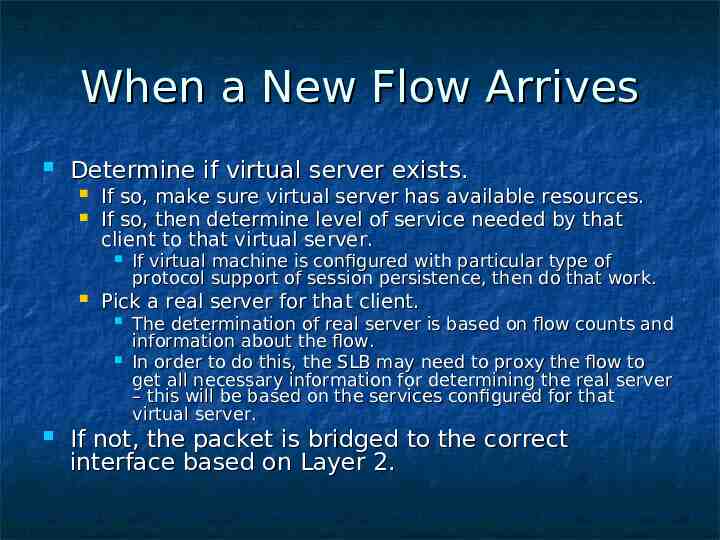
When a New Flow Arrives Determine if virtual server exists. If so, make sure virtual server has available resources. If so, then determine level of service needed by that client to that virtual server. Pick a real server for that client. If virtual machine is configured with particular type of protocol support of session persistence, then do that work. The determination of real server is based on flow counts and information about the flow. In order to do this, the SLB may need to proxy the flow to get all necessary information for determining the real server – this will be based on the services configured for that virtual server. If not, the packet is bridged to the correct interface based on Layer 2.
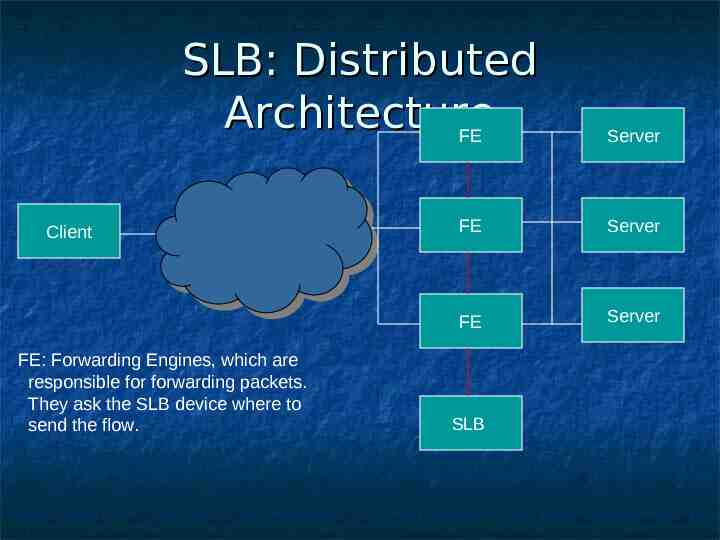
SLB: Architectures Traditional SLB device sits between the Clients and the Servers being load-balanced. Distributed SLB device sits off to the side, and only receives the packets it needs to based on flow setup and tear down.
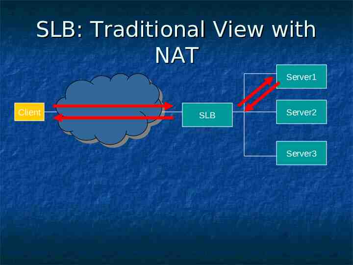
SLB: Traditional View with NAT Server1 Client SLB Server2 Server3
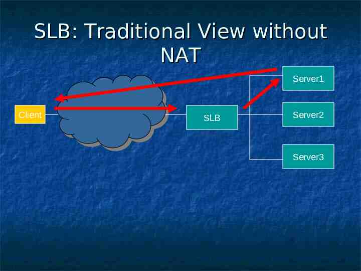
SLB: Traditional View without NAT Server1 Client SLB Server2 Server3
Load-Balance: Layer 3 / 4 Looking at the destination IP address and port to make a load-balancing decision. In order to do that, you can determine a real server based on the first packet that arrives.
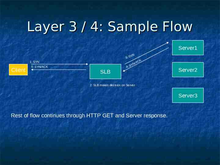
Layer 3 / 4: Sample Flow Server1 YN 3: S 1: SYN Client 5: SYN/ACK SLB CK N/A Y 4: S Server2 2: SLB makes decision on Server Server3 Rest of flow continues through HTTP GET and Server response.
Load-Balance: Layer 5 The SLB device must terminate the TCP flow for an amount of time BEFORE the SLB decision can be made. For example, the cookie value must be sent by the client, which is after the TCP handshake before determining the real server.
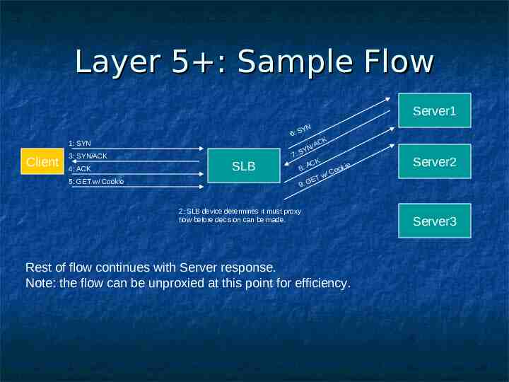
Layer 5 : Sample Flow Server1 YN 6: S 1: SYN Client 3: SYN/ACK 4: ACK 5: GET w/ Cookie SLB CK N/A Y 7: S CK kie 8: A Coo / w ET 9: G 2: SLB device determines it must proxy flow before decision can be made. Rest of flow continues with Server response. Note: the flow can be unproxied at this point for efficiency. Server2 Server3
SLB: Distributed Architecture FE Client FE: Forwarding Engines, which are responsible for forwarding packets. They ask the SLB device where to send the flow. Server FE Server FE Server SLB
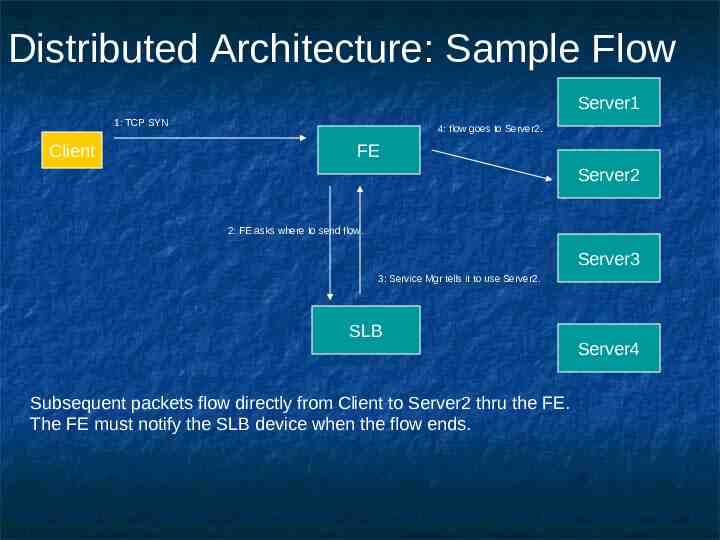
Distributed Architecture: Sample Flow Server1 1: TCP SYN Client 4: flow goes to Server2. FE Server2 2: FE asks where to send flow. Server3 3: Service Mgr tells it to use Server2. SLB Subsequent packets flow directly from Client to Server2 thru the FE. The FE must notify the SLB device when the flow ends. Server4
Server Feedback
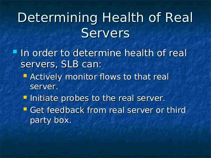
Determining Health of Real Servers In order to determine health of real servers, SLB can: Actively monitor flows to that real server. Initiate probes to the real server. Get feedback from real server or third party box.
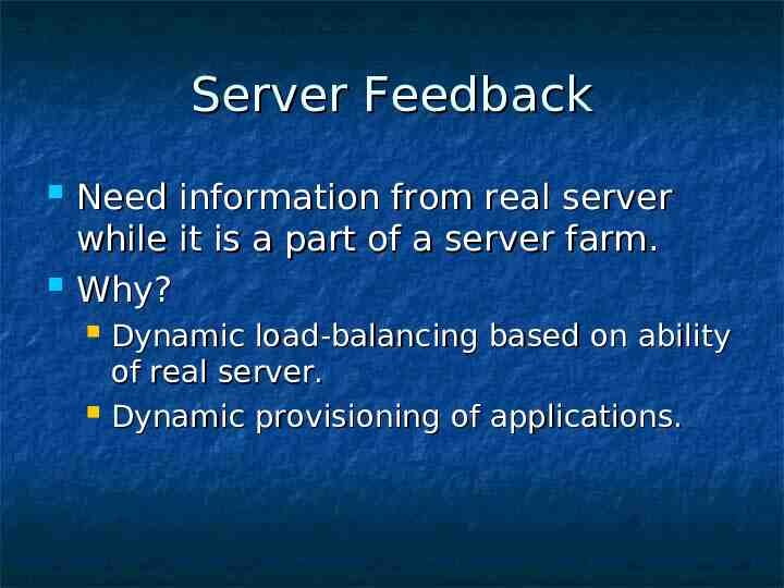
Server Feedback Need information from real server while it is a part of a server farm. Why? Dynamic load-balancing based on ability of real server. Dynamic provisioning of applications.
Server Feedback: Use of Information Availability of real server is reported as a ‘weight’ that is use by SLB algorithms (e.g., weighted round robin, weighted least connections). As weight value changes over time, the load distribution changes with it.
How to Get Weights Statically configured on SLB device – never change. Start with statically configured value on SLB device for initial start-up, then get weight from: Real server Third party box / Collection Point It is assumed that if a third party box is being used, it would be used for all the real servers in a server farm.
Direct Host Feedback Description: Have “agents” running on host to gather data points. That data is then sent to SLB device just for that physical server. Note: agent could report for different applications on that real server. Agent could be based on available memory, general resources available, proprietary information, etc.
Direct Host Feedback Pros: Have some way to dynamically change physical server’s capability for SLB flows. Cons: SLB device must attempt to normalize data for all real servers in a server farm. If have heterogeneous servers, it is difficult to do. Difficult for real server to identify itself in SLB terms for case of L3 vs. L4 vs. L5, etc SLB scenarios.
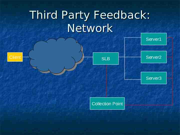
Third Party Feedback: Network Server1 Client SLB Server2 Server3 Collection Point
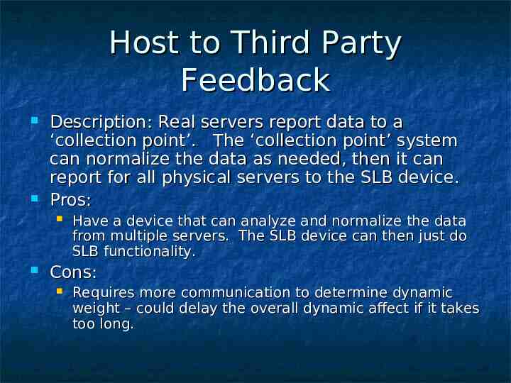
Host to Third Party Feedback Description: Real servers report data to a ‘collection point’. The ‘collection point’ system can normalize the data as needed, then it can report for all physical servers to the SLB device. Pros: Have a device that can analyze and normalize the data from multiple servers. The SLB device can then just do SLB functionality. Cons: Requires more communication to determine dynamic weight – could delay the overall dynamic affect if it takes too long.
RSerPool
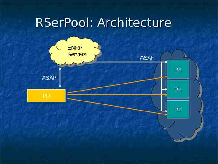
RSerPool: Architecture ENRP Servers ASAP PE ASAP PE PU PE
RSerPool: Overview RSerPool protocols sit between the user application and the IP transport protocol (session layer). The application communication is now defined over a pair of logical session layer endpoints that are dynamically mapped to transport layer addresses. When a failure occurs at the network or transport layer, the session can survive because the logical session endpoints can be mapped to alternative transport addresses. The endpoint to transport mapping is managed by distributed servers providing resiliency.
RSerPool / SLB: Unified Approach (A Work in Progress)
Unified View: Overview Preserve the RSerPool architecture: Utilize SLB distributed architecture: Any extensions or modifications are backwards compatible with current RSerPool. SLB extensions at ENRP Server and PE are optional based on pool policy chosen / implemented. Introduce FE when using SLB pool policies. Add SLB technology to the ENRP Server: SLB-specific versions of pool policies. SLB- pool policy : example SLB-WRR takes into account additional host feedback such as number of flows on each PE. Add server feedback: Enable delivery of host feedback from PEs to home ENRP Server. Enable delivery of host feedback to FE from ENRP Server.
Unified: Component Description ASAP: Between PE and ENRP Server is extended to include additional host feedback such as current number of flows on PE. Subscription service and/or polling between ENRP Server and PU allows delivery of host feedback (membership, weights, flows, etc). Encapsulation of host feedback protocol in pool element parameter. Information will be replicated among peer ENRP Servers. Subscription is between PU and current ENRP Server (not replicated). PU must be re-register subscription upon selection of new ENRP Server. Subscription and polling service previously discussed in design team as an addition to core ASAP functionality. Make decision on flow destination based on SLB-specific pool policy (i.e., load-balancing algorithm).
Unified: Component Description FE: RSerPool enabled application (PU): Uses RSerPool API for sending flows to PE. Must know which pools support which applications (SLBtypes). Add parameter to SLB-enabled PEs? Choose pool handle based on incoming client requests and supported SLB-types (SLB-L4, SLB-HTTP, SLB-SIP, etc). ASAP control plane for PE selection. Bearer plane uses flow-specific protocol (e.g., HTTP, SIP, etc) and corresponding transport (e.g., TCP, SCTP). If no other SLB-type matches, the SLB-L4 will be used. NAT, reverse NAT. Proxy service.
Unified: Component Description FE (continued): Configuration: Server Pools: Static configuration of pool handles – pool names are resolved upon initialization. Static configuration of pool handles and PE detail, including initial/default weights. Automagic configuration? Protocol Table: Maps supported SLB-types to pool handles by looking for best match in incoming packet, e.g., SLB-L4 (must implement). SLB-HTTP. SLB-SIP.
Unified: Component Description PE: SLB-enabled PEs must support dynamic host feedback.
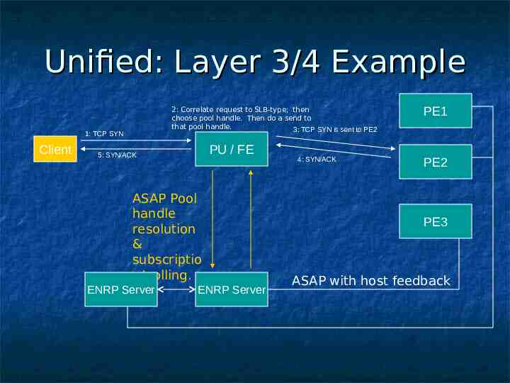
Unified: Layer 3/4 Example 2: Correlate request to SLB-type; then choose pool handle. Then do a send to that pool handle. 3: TCP SYN is sent to PE2 1: TCP SYN Client PU / FE 5: SYN/ACK ASAP Pool handle resolution & subscriptio n/polling. ENRP Server ENRP Server 4: SYN/ACK PE1 PE2 PE3 ASAP with host feedback
Server Feedback: How to Implement with RSerPool
Unified: PE Communication PEs will send their weights to ENRP server via ASAP protocol. Server agent on host provides weight to PE application. There are some protocols that exist for reporting this information. The current list: Server/Application State Protocol, SASP: Joint IBM / Cisco Protocol. IETF draft is currently available. Dynamic Feedback Protocol, DFP: Cisco developed Protocol. IETF draft is in progress.
Design Team Work Items
How to Implement: To Do List Details, Details, Details . Reconcile design with pool policy draft: Determine what information needs to be passed. Determine what algorithms need to be added where. Define SLB- pool policies . Determine best method for implementation of host feedback. Complete Layer 5 example with session persistence mechanism at FE.
How to Implement: To Do List Polling / Subscriptions. Complete DFP IETF draft, so it can be considered. Everything else.