Software Defined Network and Network Virtualization Sándor Laki


98 Slides3.91 MB
Software Defined Network and Network Virtualization Sándor Laki (Slides by Yeh-Ching Chung)
Introduction Motivation Concept Open Flow Virtual Switch SOFTWARE DEFINED NETWORK
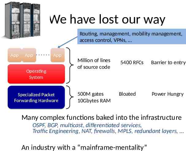
We have lost our way Routing, management, mobility management, access control, VPNs, App App App Operating System Specialized Packet Forwarding Hardware Million of lines of source code 500M gates 10Gbytes RAM 5400 RFCs Bloated Barrier to entry Power Hungry Many complex functions baked into the infrastructure OSPF, BGP, multicast, differentiated services, Traffic Engineering, NAT, firewalls, MPLS, redundant layers, An industry with a “mainframe-mentality”
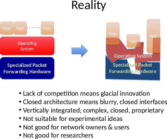
Reality App App App App Operating System App App Operating System Specialized Packet Forwarding Hardware Specialized Packet Forwarding Hardware Lack of competition means glacial innovation Closed architecture means blurry, closed interfaces Vertically integrated, complex, closed, proprietary Not suitable for experimental ideas Not good for network owners & users Not good for researchers
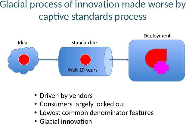
Glacial process of innovation made worse by captive standards process Deployment Idea Standardize Wait 10 years Driven by vendors Consumers largely locked out Lowest common denominator features Glacial innovation
Introduction Motivation Concept Open Flow Virtual Switch SOFTWARE DEFINED NETWORK
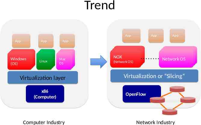
Trend App App App Windows Windows Windows (OS) (OS) (OS) Linux Linux Linux App App App Mac Mac Mac OS OS OS Virtualization layer x86 (Computer) Computer Industry Controller11 NOX Controller (Network OS) Controller Controller Network OS 22 Virtualization or “Slicing” OpenFlow Network Industry
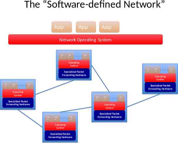
The “Software-defined Network” App App App Network Operating System Ap Ap p p Ap Ap p p Ap Ap p p Operating Operating System System Ap Ap p p Specialized Packet Forwarding Hardware Ap Ap p p Ap Ap p p Ap Ap p p Ap Ap p p Operating System Ap Ap p p Specialized Specialized Packet Packet Forwarding Forwarding Hardware Hardware Operating Operating System System Ap Ap p p Specialized Specialized Packet Packet Forwarding Hardware Forwarding Hardware Ap Ap p p Ap Ap p p Operating System Ap Ap p p Ap Ap p p Ap Ap p p Operating Operating System System Specialized Specialized Packet Packet Forwarding Hardware Forwarding Hardware Specialized Specialized Packet Packet Forwarding Forwarding Hardware Hardware
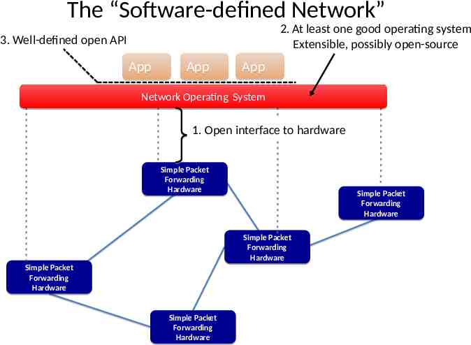
The “Software-defined Network” 2. At least one good operating system Extensible, possibly open-source 3. Well-defined open API App App App Network Operating System 1. Open interface to hardware Simple Packet Forwarding Hardware Simple Packet Forwarding Hardware Simple Packet Forwarding Hardware Simple Packet Forwarding Hardware Simple Packet Forwarding Hardware
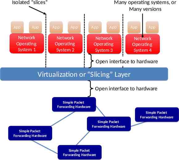
Isolated “slices” App App Network Operating System 1 Many operating systems, or Many versions App App Network Operating System 2 App App App Network Operating System 3 App Network Operating System 4 Open interface to hardware Virtualization or “Slicing” Layer Open interface to hardware Simple Packet Forwarding Hardware Simple Packet Forwarding Hardware Simple Packet Forwarding Hardware Simple Packet Forwarding Hardware Simple Packet Forwarding Hardware
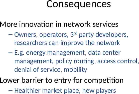
Consequences More innovation in network services – Owners, operators, 3rd party developers, researchers can improve the network – E.g. energy management, data center management, policy routing, access control, denial of service, mobility Lower barrier to entry for competition – Healthier market place, new players
Introduction Motivation Concept Open Flow Virtual Switch SOFTWARE DEFINED NETWORK
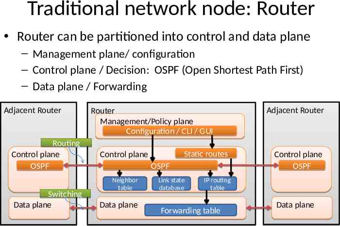
Traditional network node: Router Router can be partitioned into control and data plane – Management plane/ configuration – Control plane / Decision: OSPF (Open Shortest Path First) – Data plane / Forwarding Adjacent Router Routing Control plane OSPF Switching Data plane Router Management/Policy plane Configuration / CLI / GUI Static routes Control plane OSPF Neighbor table Data plane Link state database Adjacent Router Control plane OSPF IP routing table Forwarding table Data plane
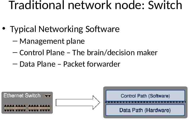
Traditional network node: Switch Typical Networking Software – Management plane – Control Plane – The brain/decision maker – Data Plane – Packet forwarder
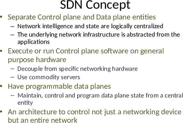
SDN Concept Separate Control plane and Data plane entities – Network intelligence and state are logically centralized – The underlying network infrastructure is abstracted from the applications Execute or run Control plane software on general purpose hardware – Decouple from specific networking hardware – Use commodity servers Have programmable data planes – Maintain, control and program data plane state from a central entity An architecture to control not just a networking device but an entire network
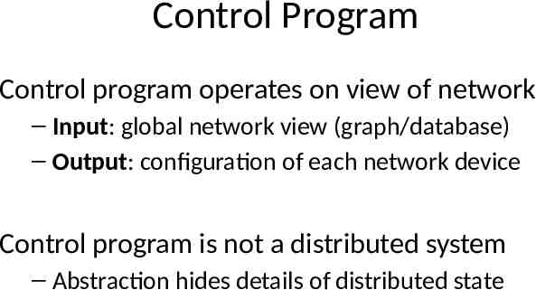
Control Program Control program operates on view of network – Input: global network view (graph/database) – Output: configuration of each network device Control program is not a distributed system – Abstraction hides details of distributed state
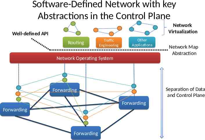
Software-Defined Network with key Abstractions in the Control Plane Network Virtualization Well-defined API Routing Traffic Engineering Other Applications Network Operating System Separation of Data and Control Plane Forwarding Forwarding Forwarding Forwarding Network Map Abstraction
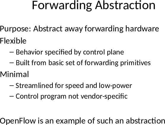
Forwarding Abstraction Purpose: Abstract away forwarding hardware Flexible – Behavior specified by control plane – Built from basic set of forwarding primitives Minimal – Streamlined for speed and low-power – Control program not vendor-specific OpenFlow is an example of such an abstraction
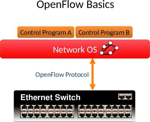
OpenFlow Basics Control Program A Control Program B Network OS OpenFlow Protocol Ethernet Switch Control Path OpenFlow Data Path (Hardware)
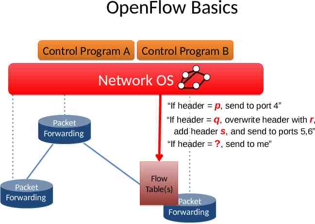
OpenFlow Basics Control Program A Control Program B Network OS “If header p, send to port 4” Packet Packet Forwarding Forwarding Packet Packet Forwarding Forwarding “If header q, overwrite header with r, add header s, and send to ports 5,6” “If header ?, send to me” Flow Table(s) Packet Packet Forwarding Forwarding
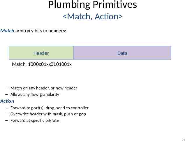
Plumbing Primitives Match, Action Match arbitrary bits in headers: Header Data Match: 1000x01xx0101001x – Match on any header, or new header – Allows any flow granularity Action – Forward to port(s), drop, send to controller – Overwrite header with mask, push or pop – Forward at specific bit-rate 21
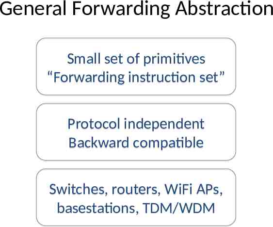
General Forwarding Abstraction Small set of primitives “Forwarding instruction set” Protocol independent Backward compatible Switches, routers, WiFi APs, basestations, TDM/WDM
Introduction Motivation Concept Open Flow Virtual Switch SOFTWARE DEFINED NETWORK
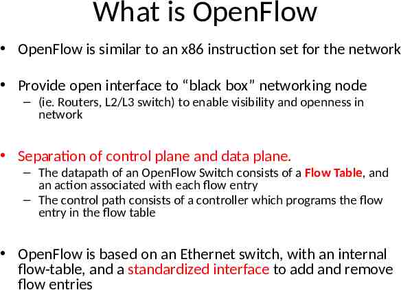
What is OpenFlow OpenFlow is similar to an x86 instruction set for the network Provide open interface to “black box” networking node – (ie. Routers, L2/L3 switch) to enable visibility and openness in network Separation of control plane and data plane. – The datapath of an OpenFlow Switch consists of a Flow Table, and an action associated with each flow entry – The control path consists of a controller which programs the flow entry in the flow table OpenFlow is based on an Ethernet switch, with an internal flow-table, and a standardized interface to add and remove flow entries
OpenFlow Consortium Goal http://OpenFlowSwitch.org – Evangelize OpenFlow to vendors – Free membership for all researchers – Whitepaper, OpenFlow Switch Specification, Reference Designs – Licensing: Free for research and commercial use
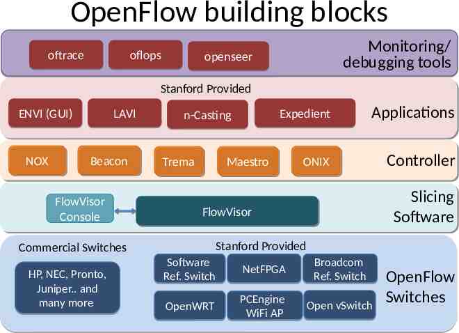
OpenFlow building blocks oftrace oflops Monitoring/ debugging tools openseer Stanford Provided ENVI (GUI) NOX NOX LAVI Beacon Beacon FlowVisor Console n-Casting Trema Trema Applications ONIX ONIX Controller Maestro Maestro Slicing Software FlowVisor FlowVisor Stanford Provided Commercial Switches HP, NEC, Pronto, Juniper. and many more Expedient Software Ref. Switch NetFPGA Broadcom Ref. Switch OpenWRT PCEngine WiFi AP Open vSwitch OpenFlow Switches 26
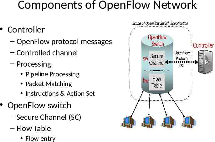
Components of OpenFlow Network Controller – OpenFlow protocol messages – Controlled channel – Processing Pipeline Processing Packet Matching Instructions & Action Set OpenFlow switch – Secure Channel (SC) – Flow Table Flow entry
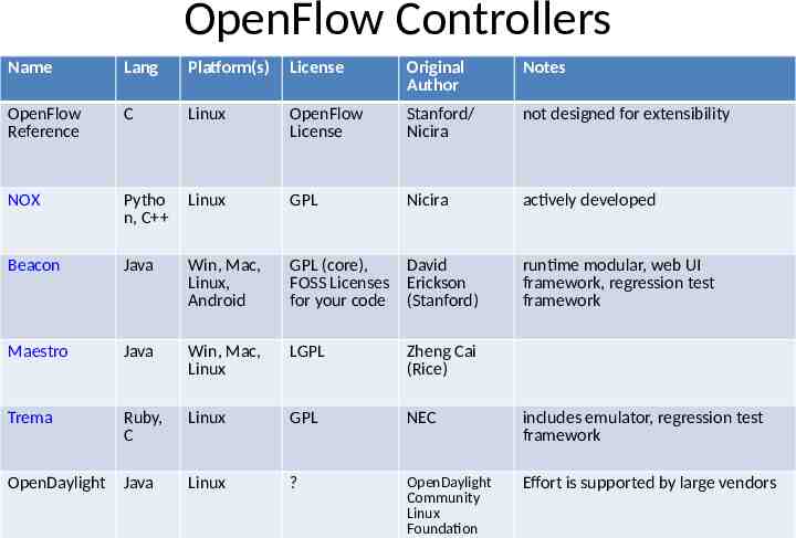
OpenFlow Controllers Name Lang Platform(s) License Original Author Notes OpenFlow Reference C Linux OpenFlow License Stanford/ Nicira not designed for extensibility NOX Pytho n, C Linux GPL Nicira actively developed Beacon Java Win, Mac, Linux, Android GPL (core), David FOSS Licenses Erickson for your code (Stanford) Maestro Java Win, Mac, Linux LGPL Zheng Cai (Rice) Trema Ruby, C Linux GPL NEC includes emulator, regression test framework OpenDaylight Java Linux ? OpenDaylight Community Linux Foundation Effort is supported by large vendors runtime modular, web UI framework, regression test framework 28
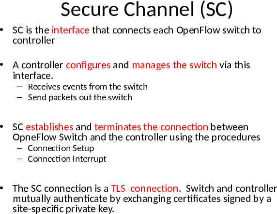
Secure Channel (SC) SC is the interface that connects each OpenFlow switch to controller A controller configures and manages the switch via this interface. – Receives events from the switch – Send packets out the switch SC establishes and terminates the connection between OpneFlow Switch and the controller using the procedures – Connection Setup – Connection Interrupt The SC connection is a TLS connection. Switch and controller mutually authenticate by exchanging certificates signed by a site-specific private key.
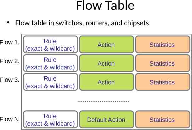
Flow Table Flow table in switches, routers, and chipsets Flow 1. Rule (exact & wildcard) Action Statistics Flow 2. Rule (exact & wildcard) Action Statistics Flow 3. Rule (exact & wildcard) Action Statistics Flow N. Rule (exact & wildcard) Default Action Statistics
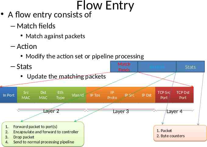
Flow Entry A flow entry consists of – Match fields Match against packets – Action Modify the action set or pipeline processing – Stats Match Fields Update the matching packets In Port Src MAC Dst MAC Eth Type Vlan Id Layer 2 1. 2. 3. 4. Forward packet to port(s) Encapsulate and forward to controller Drop packet Send to normal processing pipeline IP Tos IP Proto IP Src Layer 3 Action IP Dst Stats TCP Src Port TCP Dst Port Layer 4 1. Packet 2. Byte counters
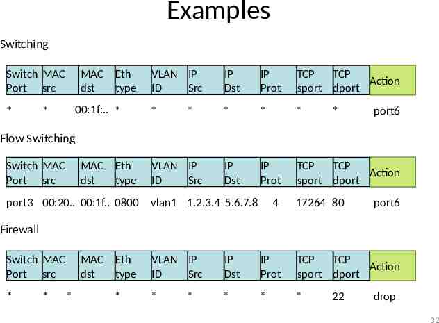
Examples Switching Switch MAC Port src * MAC Eth dst type 00:1f:. * * VLAN IP ID Src IP Dst IP Prot TCP TCP Action sport dport * * * * IP Dst IP Prot TCP TCP Action sport dport * * port6 Flow Switching Switch MAC Port src MAC Eth dst type port3 00:20. 00:1f. 0800 VLAN IP ID Src vlan1 1.2.3.4 5.6.7.8 4 17264 80 port6 Firewall Switch MAC Port src * * MAC Eth dst type * * VLAN IP ID Src IP Dst IP Prot TCP TCP Action sport dport * * * * * 22 drop 32
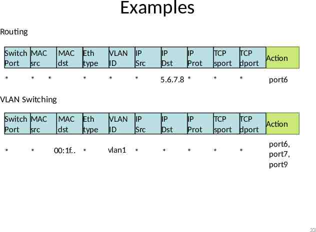
Examples Routing Switch MAC Port src * * MAC Eth dst type * * VLAN IP ID Src IP Dst * 5.6.7.8 * * IP Dst TCP TCP Action sport dport * IP Prot TCP TCP Action sport dport * port6 VLAN Switching Switch MAC Port src * * MAC Eth dst type 00:1f. * VLAN IP ID Src vlan1 * * IP Prot * * * port6, port7, port9 33
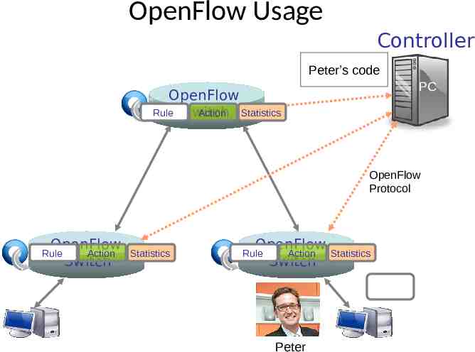
OpenFlow Usage Controller Peter’s code PC OpenFlow Rule Switch Action Statistics OpenFlow Protocol OpenFlow Action Switch Rule OpenFlowSwitch.org Statistics OpenFlow Action Switch Rule Peter Statistics
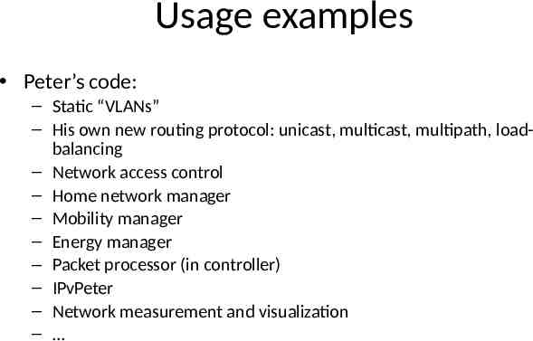
Usage examples Peter’s code: – Static “VLANs” – His own new routing protocol: unicast, multicast, multipath, loadbalancing – Network access control – Home network manager – Mobility manager – Energy manager – Packet processor (in controller) – IPvPeter – Network measurement and visualization –
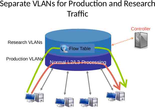
Separate VLANs for Production and Research Traffic Controller Research VLANs Flow Table Production VLANs Normal L2/L3 Processing
Dynamic Flow Aggregation on an OpenFlow Network Scope – Different Networks want different flow granularity (ISP, Backbone, ) – Switch resources are limited (flow entries, memory) – Network management is hard – Current Solutions : MPLS, IP aggregation
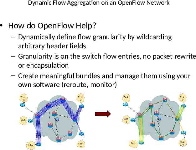
Dynamic Flow Aggregation on an OpenFlow Network How do OpenFlow Help? – Dynamically define flow granularity by wildcarding arbitrary header fields – Granularity is on the switch flow entries, no packet rewrite or encapsulation – Create meaningful bundles and manage them using your own software (reroute, monitor)
Virtualizing OpenFlow Network operators “Delegate” control of subsets of network hardware and/or traffic to other network operators or users Multiple controllers can talk to the same set of switches Imagine a hypervisor for network equipments Allow experiments to be run on the network in isolation of each other and production traffic
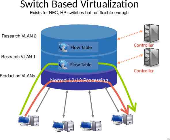
Switch Based Virtualization Exists for NEC, HP switches but not flexible enough Research VLAN 2 Flow Table Controller Research VLAN 1 Flow Table Controller Production VLANs Normal L2/L3 Processing 40
FlowVisor A network hypervisor developed by Stanford A software proxy between the forwarding and control planes of network devices
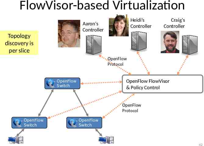
FlowVisor-based Virtualization Heidi’s Controller Aaron’s Controller Craig’s Controller Topology discovery is per slice OpenFlow OpenFlow Protocol Protocol OpenFlow Switch OpenFlow FlowVisor & Policy Control OpenFlow OpenFlow Protocol Protocol OpenFlow Switch OpenFlow Switch 42
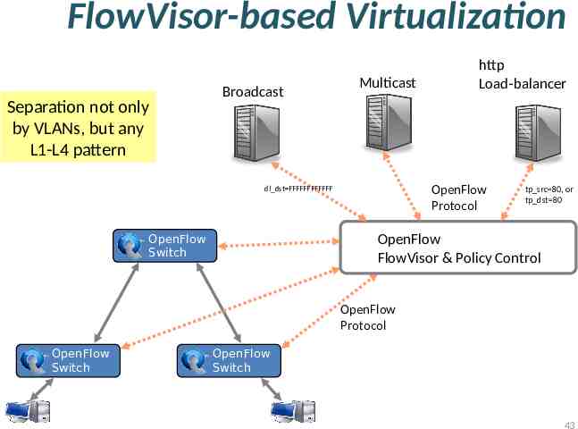
FlowVisor-based Virtualization Separation not only by VLANs, but any L1-L4 pattern Broadcast Multicast OpenFlow Protocol dl dst FFFFFFFFFFFF OpenFlow Switch http Load-balancer tp src 80, or tp dst 80 OpenFlow FlowVisor & Policy Control OpenFlow Protocol OpenFlow Switch OpenFlow Switch 43
FlowVisor Slicing Slices are defined using a slice definition policy – The policy language specifies the slice’s resource limits, flowspace, and controller’s location in terms of IP and TCP port-pair – FlowVisor enforces transparency and isolation between slices by inspecting, rewriting, and policing OpenFlow messages as they pass
FlowVisor Resource Limits FV assigns hardware resources to “Slices” – Topology Network Device or Openflow Instance (DPID) Physical Ports – Bandwidth Each slice can be assigned a per port queue with a fraction of the total bandwidth – CPU Employs Course Rate Limiting techniques to keep new flow events from one slice from overrunning the CPU – Forwarding Tables Each slice has a finite quota of forwarding rules per device
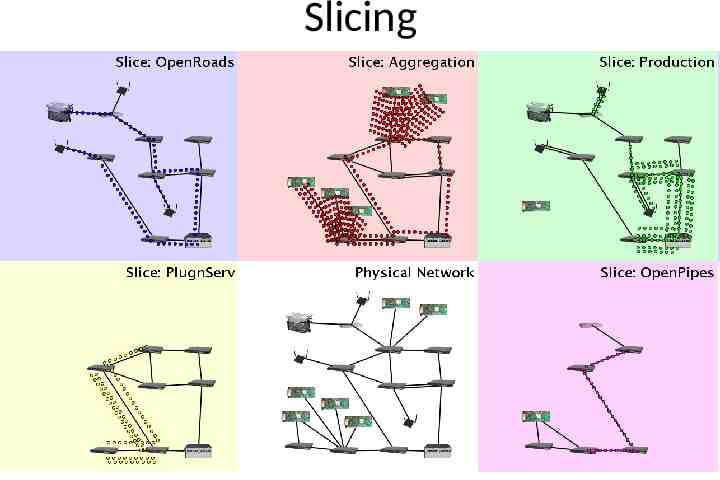
Slicing
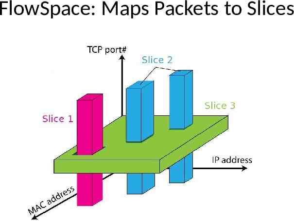
FlowVisor FlowSpace FlowSpace is defined by a collection of packet headers and assigned to “Slices” – Source/Destination MAC address – VLAN ID – Ethertype – IP protocol – Source/Destination IP address – ToS/DSCP – Source/Destination port number
FlowSpace: Maps Packets to Slices
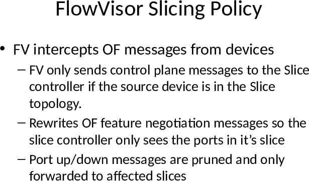
FlowVisor Slicing Policy FV intercepts OF messages from devices – FV only sends control plane messages to the Slice controller if the source device is in the Slice topology. – Rewrites OF feature negotiation messages so the slice controller only sees the ports in it’s slice – Port up/down messages are pruned and only forwarded to affected slices
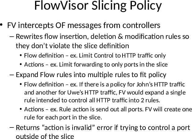
FlowVisor Slicing Policy FV intercepts OF messages from controllers – Rewrites flow insertion, deletion & modification rules so they don’t violate the slice definition Flow definition – ex. Limit Control to HTTP traffic only Actions – ex. Limit forwarding to only ports in the slice – Expand Flow rules into multiple rules to fit policy Flow definition – ex. If there is a policy for John’s HTTP traffic and another for Uwe’s HTTP traffic, FV would expand a single rule intended to control all HTTP traffic into 2 rules. Actions – ex. Rule action is send out all ports. FV will create one rule for each port in the slice. – Returns “action is invalid” error if trying to control a port outside of the slice
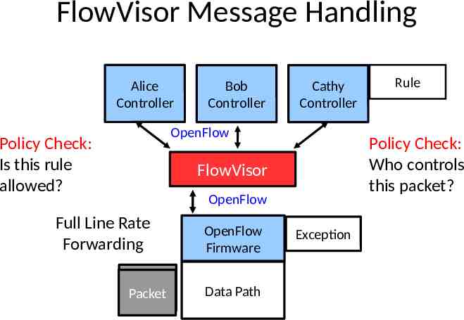
FlowVisor Message Handling Alice Controller Bob Controller Cathy Controller OpenFlow Policy Check: Is this rule allowed? Policy Check: Who controls this packet? FlowVisor OpenFlow Full Line Rate Forwarding Packet Packet OpenFlow Firmware Data Path Rule Exception
Introduction Motivation Concept Open Flow Virtual Switch SOFTWARE DEFINED NETWORK
INTRODUCTION Due to the cloud computing service, the number of virtual switches begins to expand dramatically – Management complexity, security issues and even performance degradation Software/hardware based virtual switches as well as integration of open-source hypervisor with virtual switch technology is exhibited 53
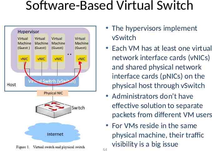
Software-Based Virtual Switch The hypervisors implement vSwitch Each VM has at least one virtual network interface cards (vNICs) and shared physical network interface cards (pNICs) on the physical host through vSwitch Administrators don’t have effective solution to separate packets from different VM users For VMs reside in the same physical machine, their traffic visibility is a big issue 54
Issues of Traditional vSwitch The traditional vSwitches lack of advanced networking features such as VLAN, port mirror, port channel, etc. Some hypervisor vSwitch vendors provide technologies to fix the above problems – OpenvSwitch may be superior in quality for the reasons 55
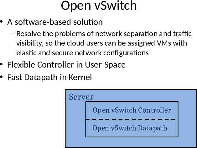
Open vSwitch A software-based solution – Resolve the problems of network separation and traffic visibility, so the cloud users can be assigned VMs with elastic and secure network configurations Flexible Controller in User-Space Fast Datapath in Kernel Server Open vSwitch Controller Open vSwitch Datapath
Open vSwitch Concepts Multiple ports to physical switches – A port may have one or more interfaces Bonding allows more than once interface per port Packets are forwarded by flow Visibility – NetFlow – sFlow – Mirroring (SPAN/RSPAN/ERSPAN) IEEE 802.1Q Support – Enable virtual LAN function – By attaching VLAN ID to Linux virtual interfaces, each user will have its own LAN environment separated from other users
Open vSwitch Concepts Fine-grained ACLs and QoS policies – L2- ‐L4 matching – Actions to forward, drop, modify, and queue – HTB and HFSC queuing disciplines Centralized control through OpenFlow Works on Linux-based hypervisors: – Xen – XenServer – KVM – VirtualBox
Open vSwitch Contributors(Partial)
Packets are Managed as Flows A flow may be identied by any combination of – Input port – VLAN ID (802.1Q) – Ethernet Source MAC address – Ethernet Destination MAC address – IP Source MAC address – IP Destination MAC address – TCP/UDP/. Source Port – TCP/UDP/. Destination Port
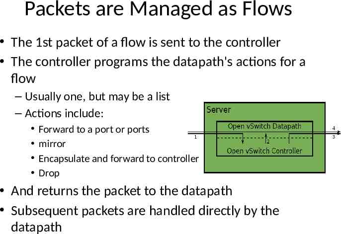
Packets are Managed as Flows The 1st packet of a flow is sent to the controller The controller programs the datapath's actions for a flow – Usually one, but may be a list – Actions include: Forward to a port or ports mirror Encapsulate and forward to controller Drop And returns the packet to the datapath Subsequent packets are handled directly by the datapath
Migration KVM and Xen provide Live Migration With bridging, IP address migration must occur with in the same L2 network Open vSwitch avoids this problem using GRE tunnels
Hardware-Based Virtual Switch Why hardware-based? – Software virtual switches consume CPU and memory usage – Possible inconsistence of network and server configurations may cause errors and is very hard to troubleshooting and maintenance Hardware-based virtual switch solution emerges for better resource utilization and configuration consistency 63
Virtual Ethernet Port Aggregator A standard led by HP, Extreme, IBM, Brocade, Juniper, etc. An emerging technology as part of IEEE 802.1Qbg Edge Virtual Bridge (EVB) standard The main goal of VEPA is to allow traffic of VMs to exit and re-enter the same server physical port to enable switching among VMs 64
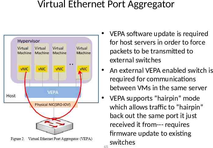
Virtual Ethernet Port Aggregator VEPA software update is required for host servers in order to force packets to be transmitted to external switches An external VEPA enabled switch is required for communications between VMs in the same server VEPA supports “hairpin” mode which allows traffic to “hairpin” back out the same port it just received it from--- requires firmware update to existing switches 65
Pros. and Cons. for VEPA Pros – Minor software/firmware update, network configuration maintained by external switches Cons – VEPA still consumes server resources in order to perform forwarding table lookup 66
References "OpenFlow: Enabling Innovation in Campus Networks“ N. McKeown, T. Andershnan, G. Parulkar, L. Peterson, J. Rexford, S. Shenker, and J. Turneron, H. Balakris ACM Computer Communication Review, Vol. 38, Issue 2, pp. 69-74 April 2008 OpenFlow Switch Specication V 1.1.0. Richard Wang, Dana Butnariu, and Jennifer Rexford OpenFlow-based server load balancing gone wild, Workshop on Hot Topics in Management of Internet, Cloud, and Enterprise 66 IP Infusion Proprietary and Confidential, released under Customer NDA , Roadmap items subject to change without notice 2011 IP Infusion Inc. gone wild, Workshop on Hot Topics in Management of Internet, Cloud, and Enterprise Networks and Services (Hot-ICE), Boston, MA, March 2011. Saurav Das, Guru Parulkar, Preeti Singh, Daniel Getachew, Lyndon Ong, Nick McKeown, Packet and Circuit Network Convergence with OpenFlow, Optical Fiber Conference (OFC/NFOEC'10), San Diego, March 2010 Nikhil Handigol, Srini Seetharaman, Mario Flajslik, Nick McKeown, Ramesh Johari, Plug-n-Serve: Load-Balancing Web Traffic using OpenFlow, ACM SIGCOMM Demo, Aug 2009. NOX: Towards an Operating System for Networks https://sites.google.com/site/routeflow/home http://www.openflow.org/ http://www.opennetsummit.org/ https://www.opennetworking.org/ http://conferences.sigcomm.org/sigcomm/2010/papers/sigcomm/p195.pdf http://searchnetworking.techtarget.com/
References Network Virtualization with Cloud Virtual Switch S. Horman, “An Introduction to Open vSwitch,” LinuxCon Japan, Yokohama, Jun. 2, 2011. J. Pettit, J. Gross “Open vSwitch Overview,” Linux Collaboration Summit, San Francisco, Apr. 7, 2011. J. Pettit, “Open vSwitch: A Whirlwind Tour,” Mar. 3, 2011. Access Layer Network Virtualization: VN-Tag and VEPA OpenFlow Tutorial
Network Virtualization
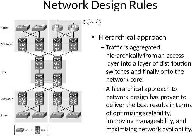
Network Design Rules Hierarchical approach – Traffic is aggregated hierarchically from an access layer into a layer of distribution switches and finally onto the network core. – A hierarchical approach to network design has proven to deliver the best results in terms of optimizing scalability, improving manageability, and maximizing network availability.
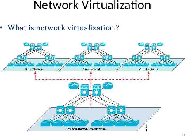
Network Virtualization What is network virtualization ? 71
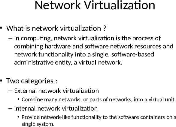
Network Virtualization What is network virtualization ? – In computing, network virtualization is the process of combining hardware and software network resources and network functionality into a single, software-based administrative entity, a virtual network. Two categories : – External network virtualization Combine many networks, or parts of networks, into a virtual unit. – Internal network virtualization Provide network-like functionality to the software containers on a single system.
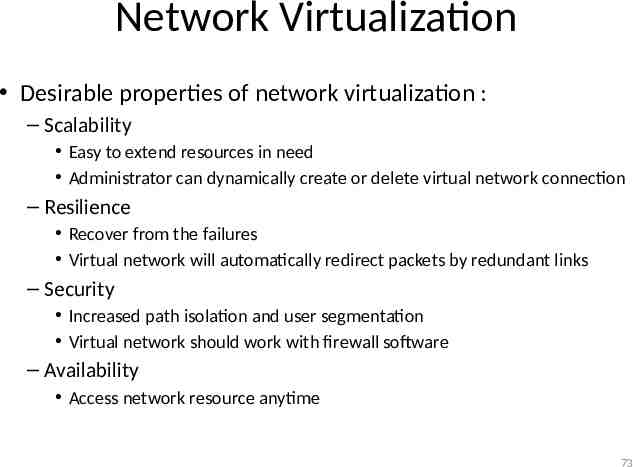
Network Virtualization Desirable properties of network virtualization : – Scalability Easy to extend resources in need Administrator can dynamically create or delete virtual network connection – Resilience Recover from the failures Virtual network will automatically redirect packets by redundant links – Security Increased path isolation and user segmentation Virtual network should work with firewall software – Availability Access network resource anytime 73
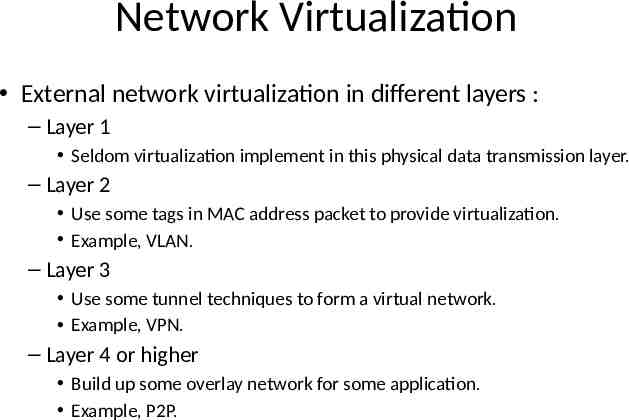
Network Virtualization External network virtualization in different layers : – Layer 1 Seldom virtualization implement in this physical data transmission layer. – Layer 2 Use some tags in MAC address packet to provide virtualization. Example, VLAN. – Layer 3 Use some tunnel techniques to form a virtual network. Example, VPN. – Layer 4 or higher Build up some overlay network for some application. Example, P2P.
Network Virtualization Internal network virtualization in different layers : – Layer 1 Hypervisor usually do not need to emulate the physical layer. – Layer 2 Implement virtual L2 network devices, such as switch, in hypervisor. Example, Linux TAP driver Linux bridge. – Layer 3 Implement virtual L3 network devices, such as router, in hypervisor. Example, Linux TUN driver Linux bridge iptables. – Layer 4 or higher Layer 4 or higher layers virtualization is usually implemented in guest OS. Applications should make their own choice.
Introduction External network virtualization Internal network virtualization NETWORK VIRTUALIZATION
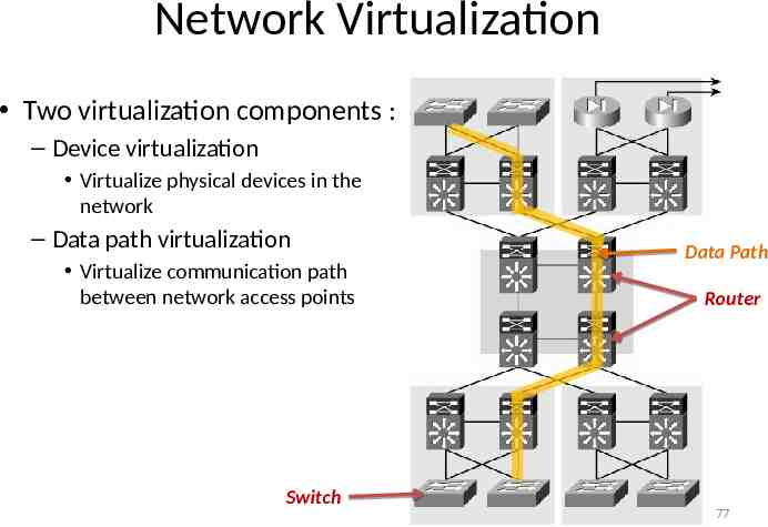
Network Virtualization Two virtualization components : – Device virtualization Virtualize physical devices in the network – Data path virtualization Virtualize communication path between network access points Switch Data Path Router 77
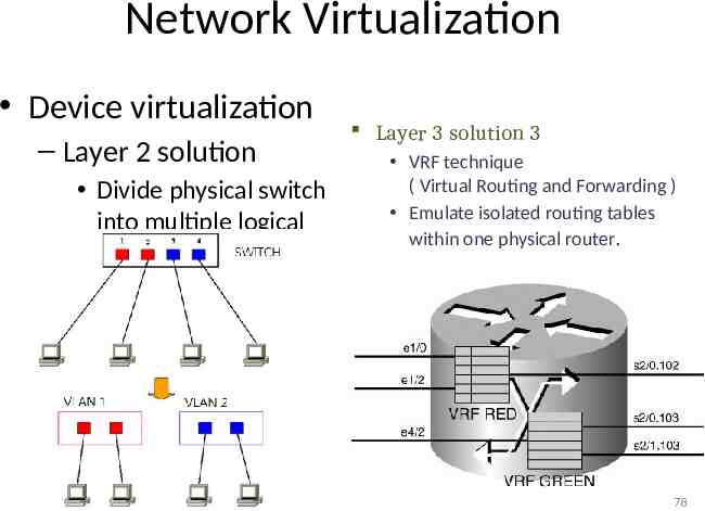
Network Virtualization Device virtualization – Layer 2 solution Divide physical switch into multiple logical switches. Layer 3 solution 3 VRF technique ( Virtual Routing and Forwarding ) Emulate isolated routing tables within one physical router. 78
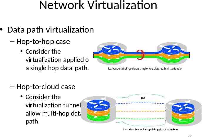
Network Virtualization Data path virtualization – Hop-to-hop case Consider the virtualization applied on a single hop data-path. – Hop-to-cloud case Consider the virtualization tunnels allow multi-hop datapath. 79
Network Virtualization Protocol approach – Protocols usually use for data-path virtualization. – Three implementations 802.1Q – implement hop to hop data-path virtualization MPLS ( Multiprotocol Label Switch ) – implement router and switch layer virtualization GRE (Generic Routing Encapsulation ) – implement virtualization among wide variety of networks with tunneling technique. 80
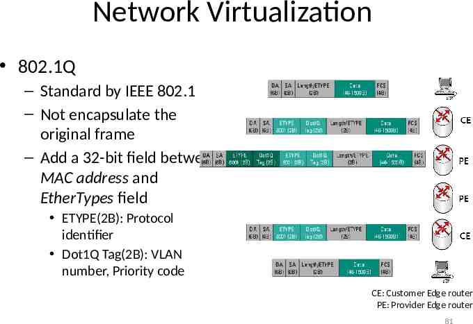
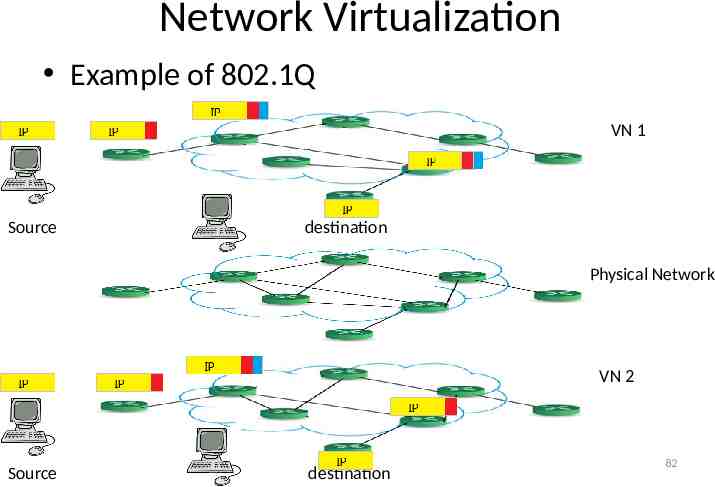
Network Virtualization 802.1Q – Standard by IEEE 802.1 – Not encapsulate the original frame – Add a 32-bit field between MAC address and EtherTypes field ETYPE(2B): Protocol identifier Dot1Q Tag(2B): VLAN number, Priority code CE: Customer Edge router PE: Provider Edge router 81
Network Virtualization Example of 802.1Q VN 1 Source destination Physical Network VN 2 Source destination 82
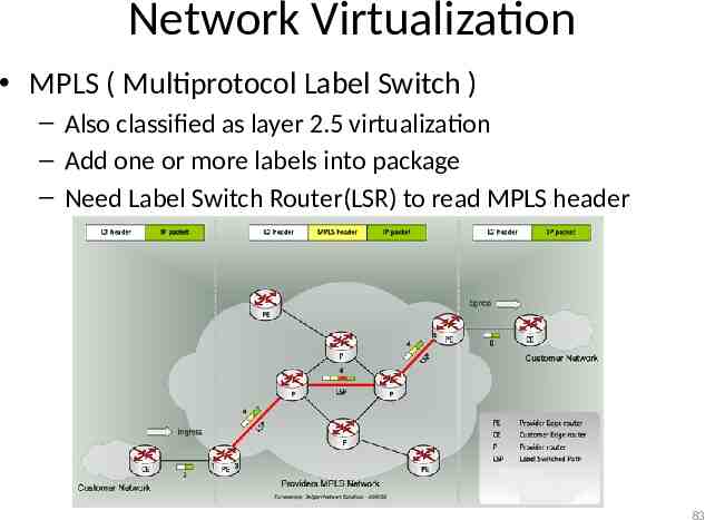
Network Virtualization MPLS ( Multiprotocol Label Switch ) – Also classified as layer 2.5 virtualization – Add one or more labels into package – Need Label Switch Router(LSR) to read MPLS header 83
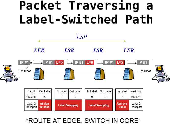
Packet Traversing a Label-Switched Path
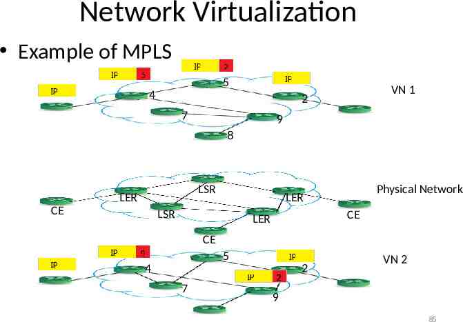
Network Virtualization Example of MPLS 5 4 VN 1 2 7 9 8 LSR LER CE Physical Network LER LSR CE LER CE 5 4 7 2 VN 2 9 85
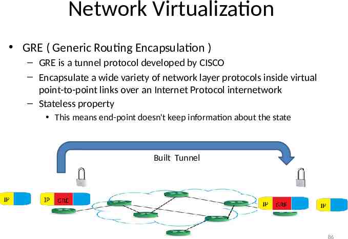
Network Virtualization GRE ( Generic Routing Encapsulation ) – GRE is a tunnel protocol developed by CISCO – Encapsulate a wide variety of network layer protocols inside virtual point-to-point links over an Internet Protocol internetwork – Stateless property This means end-point doesn't keep information about the state Built Tunnel 86
Introduction External network virtualization Internal network virtualization NETWORK VIRTUALIZATION
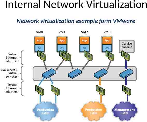
Internal Network Virtualization Internal network virtualization – A single system is configured with containers, such as the Xen domain, combined with hypervisor control programs or pseudointerfaces such as the VNIC, to create a “network in a box”. – This solution improves overall efficiency of a single system by isolating applications to separate containers and/or pseudo interfaces. – Virtual machine and virtual switch : The VMs are connected logically to each other so that they can send data to and receive data from each other. Each virtual network is serviced by a single virtual switch. A virtual network can be connected to a physical network by associating one or more network adapters (uplink adapters) with the virtual switch.
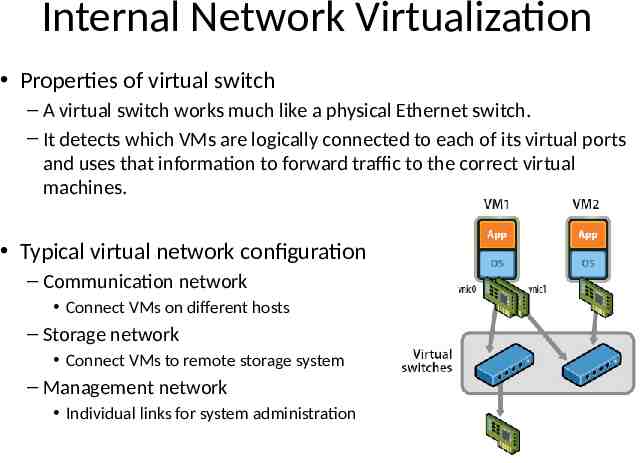
Internal Network Virtualization Properties of virtual switch – A virtual switch works much like a physical Ethernet switch. – It detects which VMs are logically connected to each of its virtual ports and uses that information to forward traffic to the correct virtual machines. Typical virtual network configuration – Communication network Connect VMs on different hosts – Storage network Connect VMs to remote storage system – Management network Individual links for system administration
Internal Network Virtualization Network virtualization example form VMware
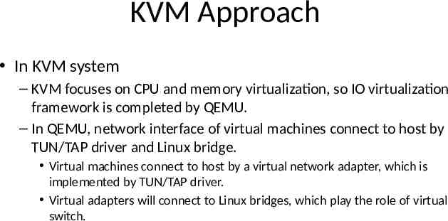
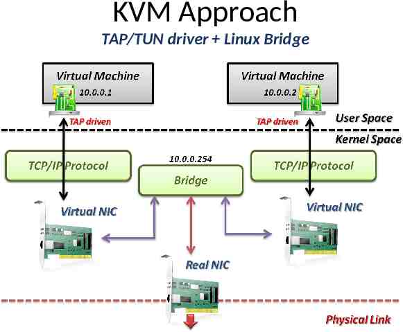
KVM Approach In KVM system – KVM focuses on CPU and memory virtualization, so IO virtualization framework is completed by QEMU. – In QEMU, network interface of virtual machines connect to host by TUN/TAP driver and Linux bridge. Virtual machines connect to host by a virtual network adapter, which is implemented by TUN/TAP driver. Virtual adapters will connect to Linux bridges, which play the role of virtual switch.
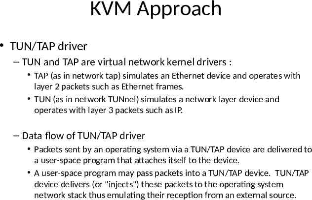
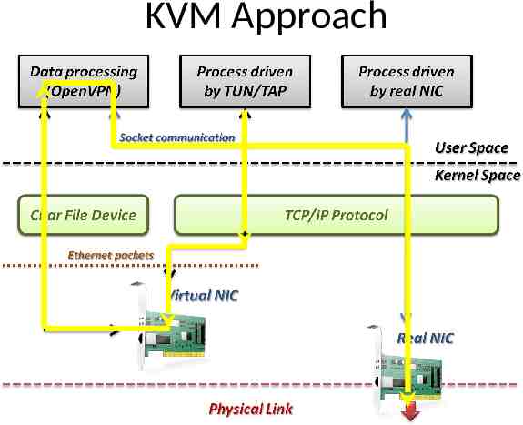
KVM Approach TUN/TAP driver – TUN and TAP are virtual network kernel drivers : TAP (as in network tap) simulates an Ethernet device and operates with layer 2 packets such as Ethernet frames. TUN (as in network TUNnel) simulates a network layer device and operates with layer 3 packets such as IP. – Data flow of TUN/TAP driver Packets sent by an operating system via a TUN/TAP device are delivered to a user-space program that attaches itself to the device. A user-space program may pass packets into a TUN/TAP device. TUN/TAP device delivers (or "injects") these packets to the operating system network stack thus emulating their reception from an external source.
KVM Approach
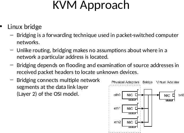
KVM Approach Linux bridge – Bridging is a forwarding technique used in packet-switched computer networks. – Unlike routing, bridging makes no assumptions about where in a network a particular address is located. – Bridging depends on flooding and examination of source addresses in received packet headers to locate unknown devices. – Bridging connects multiple network segments at the data link layer (Layer 2) of the OSI model.
KVM Approach TAP/TUN driver Linux Bridge
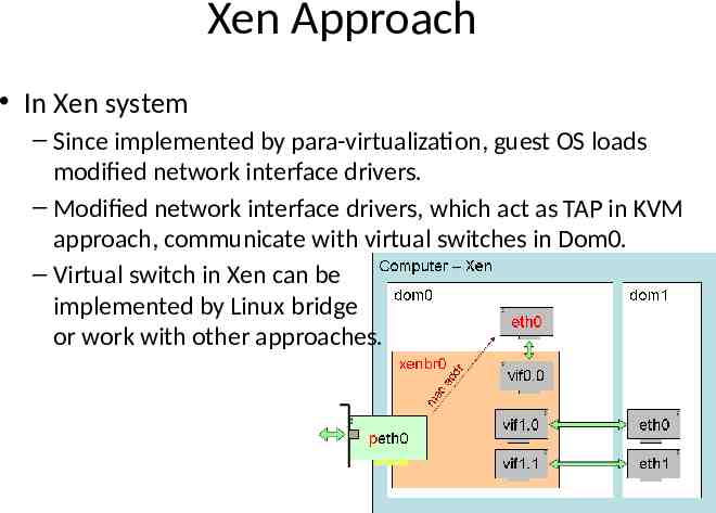
Xen Approach In Xen system – Since implemented by para-virtualization, guest OS loads modified network interface drivers. – Modified network interface drivers, which act as TAP in KVM approach, communicate with virtual switches in Dom0. – Virtual switch in Xen can be implemented by Linux bridge or work with other approaches.
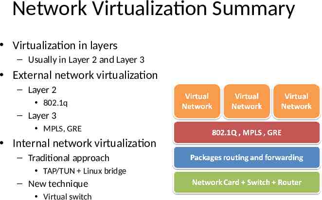
Network Virtualization Summary Virtualization in layers – Usually in Layer 2 and Layer 3 External network virtualization – Layer 2 802.1q – Layer 3 MPLS, GRE Internal network virtualization – Traditional approach TAP/TUN Linux bridge – New technique Virtual switch
Reference Books : – Kumar Reddy & Victor Moreno, Network Virtualization, Cisco Press 2006 Web resources : – Linux Bridge http://www.ibm.com/developerworks/cn/linux/l-tuntap/index.html – Xen networking http://wiki.xensource.com/xenwiki/XenNetworking – VMware Virtual Networking Concepts http://www.vmware.com/files/pdf/virtual networking concepts.pdf – TUN/TAP wiki http://en.wikipedia.org/wiki/TUN/TAP – Network Virtualization wiki http://en.wikipedia.org/wiki/Network virtualization Papers : – A. Menon, A. Cox, and W. Zwaenepoel. Optimizing Network Virtualization in Xen. Proc. USENIX Annual Technical Conference (USENIX 2006), pages 15–28, 2006.