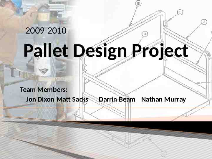
2009-2010 Pallet Design Project Team Members: Jon Dixon Matt Sacks

20 Slides3.92 MB
2009-2010 Pallet Design Project Team Members: Jon Dixon Matt Sacks Darrin Beam Nathan Murray
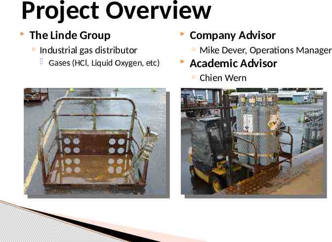
Project Overview The Linde Group Industrial gas distributor Gases (HCl, Liquid Oxygen, etc) Company Advisor Mike Dever, Operations Manager Academic Advisor Chien Wern
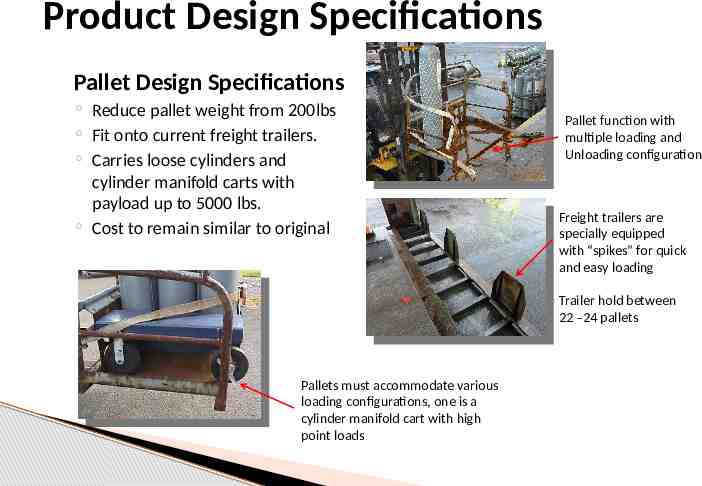
Product Design Specifications Pallet Design Specifications Reduce pallet weight from 200lbs Fit onto current freight trailers. Carries loose cylinders and cylinder manifold carts with payload up to 5000 lbs. Cost to remain similar to original Pallet function with multiple loading and Unloading configuration Freight trailers are specially equipped with “spikes” for quick and easy loading Trailer hold between 22 –24 pallets Pallets must accommodate various loading configurations, one is a cylinder manifold cart with high point loads
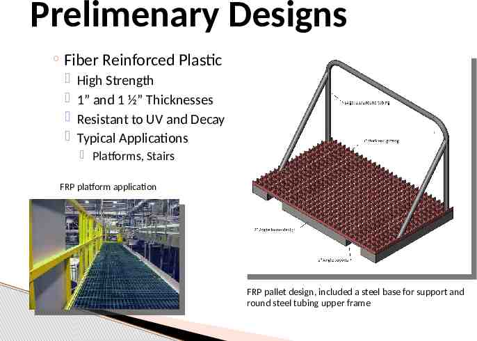
Prelimenary Designs Fiber Reinforced Plastic High Strength 1” and 1 ½” Thicknesses Resistant to UV and Decay Typical Applications Platforms, Stairs FRP platform application FRP pallet design, included a steel base for support and round steel tubing upper frame
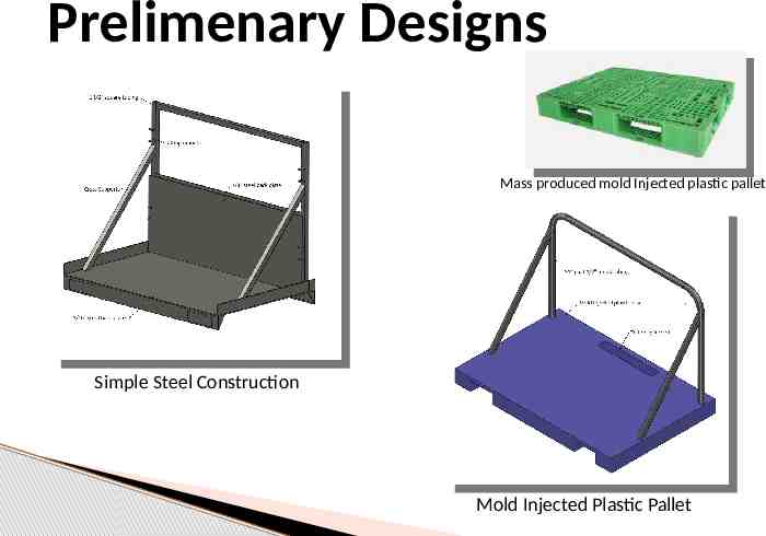
Prelimenary Designs Mass produced mold Injected plastic pallet Simple Steel Construction Mold Injected Plastic Pallet
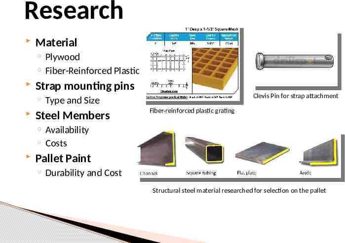
Research Material Plywood Fiber-Reinforced Plastic Strap mounting pins Clevis Pin for strap attachment Type and Size Steel Members Fiber-reinforced plastic grating Availability Costs Pallet Paint Durability and Cost Structural steel material researched for selection on the pallet
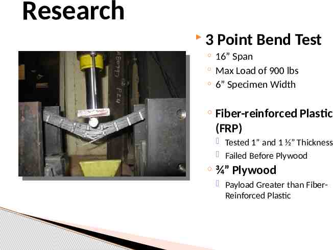
Research 3 Point Bend Test 16” Span Max Load of 900 lbs 6” Specimen Width Fiber-reinforced Plastic (FRP) Tested 1” and 1 ½” Thickness Failed Before Plywood ¾” Plywood Payload Greater than FiberReinforced Plastic
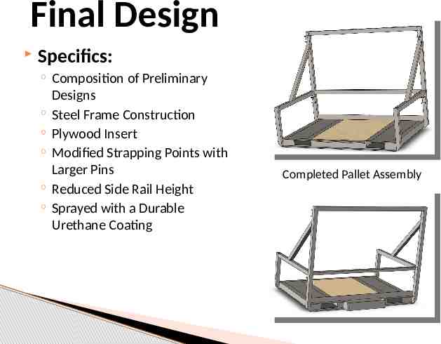
Final Design Specifics: Composition of Preliminary Designs Steel Frame Construction Plywood Insert Modified Strapping Points with Larger Pins Reduced Side Rail Height Sprayed with a Durable Urethane Coating Completed Pallet Assembly
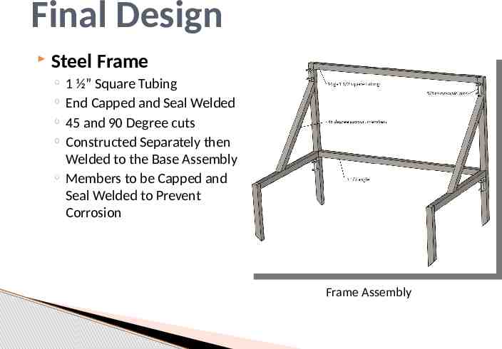
Final Design Steel Frame 1 ½” Square Tubing End Capped and Seal Welded 45 and 90 Degree cuts Constructed Separately then Welded to the Base Assembly Members to be Capped and Seal Welded to Prevent Corrosion Frame Assembly
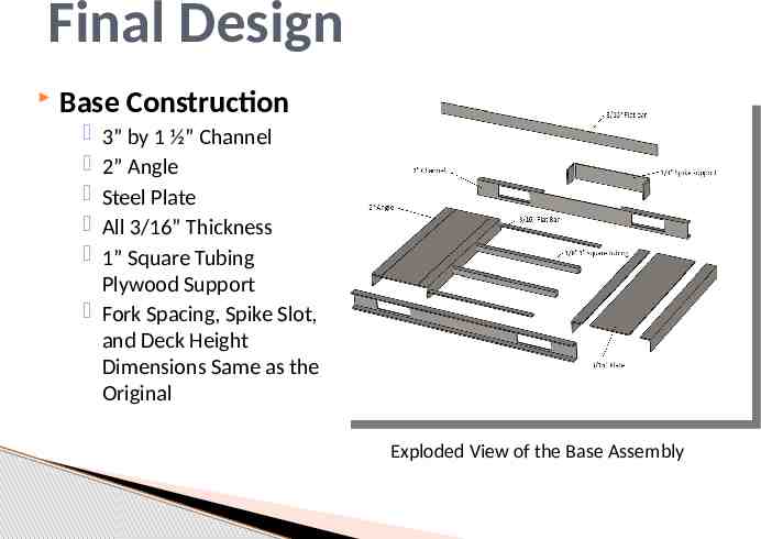
Final Design Base Construction 3” by 1 ½” Channel 2” Angle Steel Plate All 3/16” Thickness 1” Square Tubing Plywood Support Fork Spacing, Spike Slot, and Deck Height Dimensions Same as the Original Exploded View of the Base Assembly
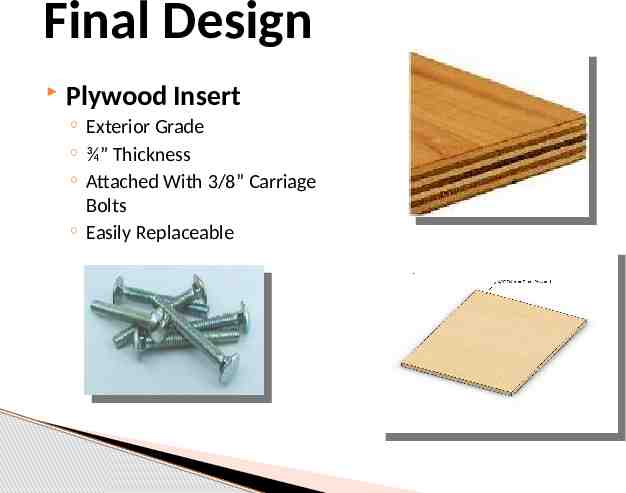
Final Design Plywood Insert Exterior Grade ¾” Thickness Attached With 3/8” Carriage Bolts Easily Replaceable
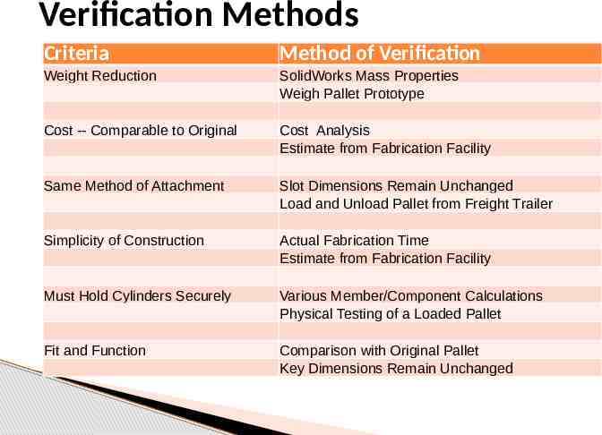
Verification Methods Criteria Method of Verification Weight Reduction SolidWorks Mass Properties Weigh Pallet Prototype Cost -- Comparable to Original Cost Analysis Estimate from Fabrication Facility Same Method of Attachment Slot Dimensions Remain Unchanged Load and Unload Pallet from Freight Trailer Simplicity of Construction Actual Fabrication Time Estimate from Fabrication Facility Must Hold Cylinders Securely Various Member/Component Calculations Physical Testing of a Loaded Pallet Fit and Function Comparison with Original Pallet Key Dimensions Remain Unchanged
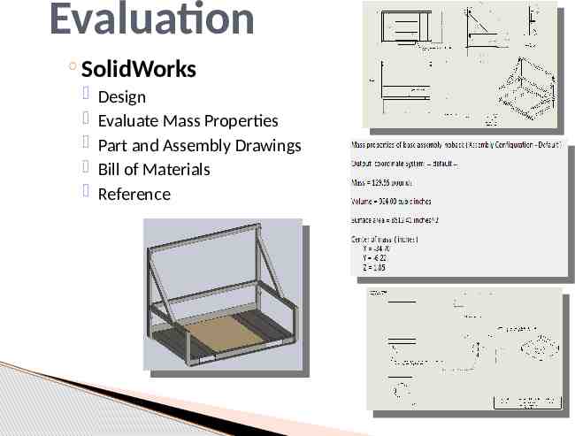
Evaluation SolidWorks Design Evaluate Mass Properties Part and Assembly Drawings Bill of Materials Reference
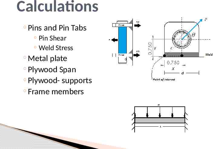
Calculations Pins and Pin Tabs Pin Shear Weld Stress Metal plate Plywood Span Plywood- supports Frame members
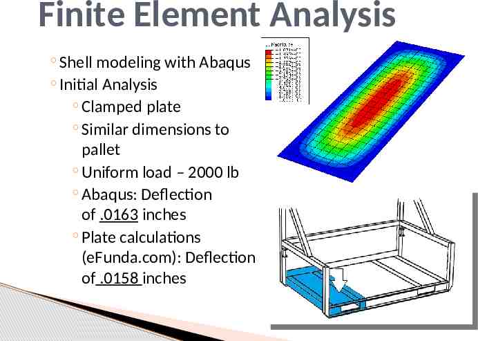
Finite Element Analysis Shell modeling with Abaqus Initial Analysis Clamped plate Similar dimensions to pallet Uniform load – 2000 lb Abaqus: Deflection of .0163 inches Plate calculations (eFunda.com): Deflection of .0158 inches
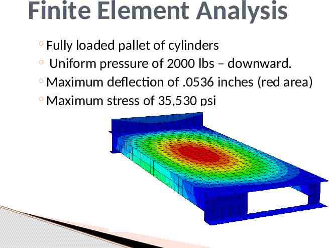
Finite Element Analysis Fully loaded pallet of cylinders Uniform pressure of 2000 lbs – downward. Maximum deflection of .0536 inches (red area) Maximum stress of 35,530 psi
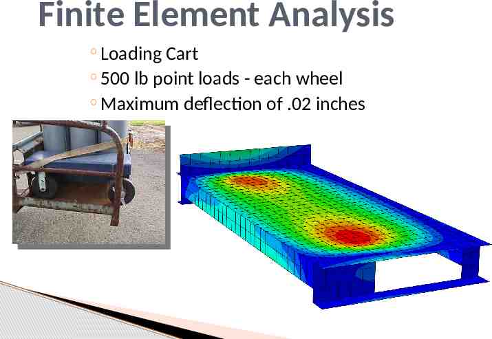
Finite Element Analysis Loading Cart 500 lb point loads - each wheel Maximum deflection of .02 inches
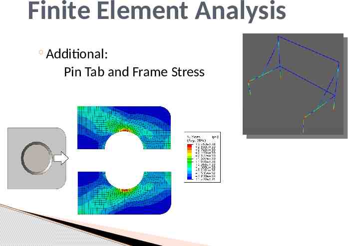
Finite Element Analysis Additional: Pin Tab and Frame Stress
Conclusion Objective Cost Weight Unexpected Deck height restriction Greater communication and understanding with customer
Questions?