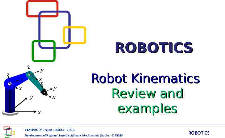
ROBOTICS z z z y y x z x y x y x Robot Kinematics Review and examples
46 Slides1.34 MB
ROBOTICS z z z y y x z x y x y x Robot Kinematics Review and examples TEMPUS IV Project: 158644 – JPCR Development of Regional Interdisciplinary Mechatronic Studies - DRIMS ROBOTICS
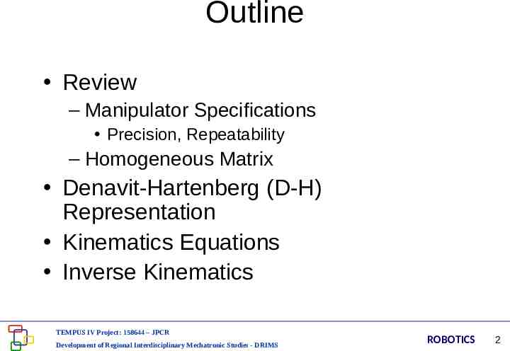
Outline Review – Manipulator Specifications Precision, Repeatability – Homogeneous Matrix Denavit-Hartenberg (D-H) Representation Kinematics Equations Inverse Kinematics TEMPUS IV Project: 158644 – JPCR Development of Regional Interdisciplinary Mechatronic Studies - DRIMS ROBOTICS 2
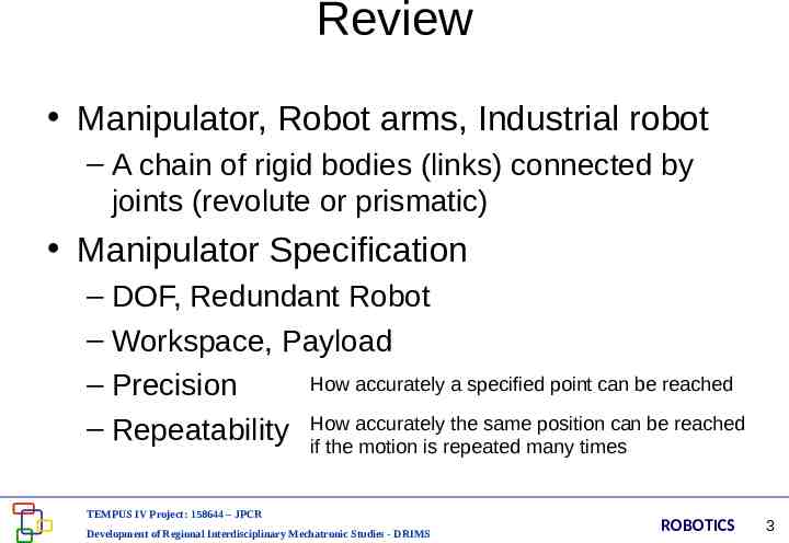
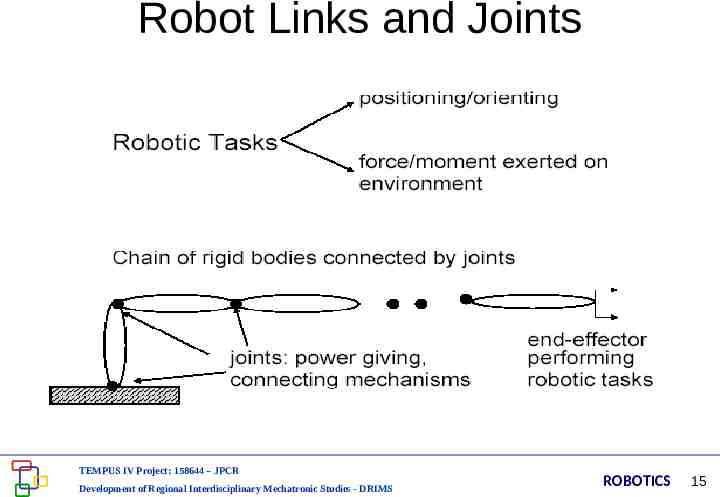
Review Manipulator, Robot arms, Industrial robot – A chain of rigid bodies (links) connected by joints (revolute or prismatic) Manipulator Specification – DOF, Redundant Robot – Workspace, Payload How accurately a specified point can be reached – Precision accurately the same position can be reached – Repeatability How if the motion is repeated many times TEMPUS IV Project: 158644 – JPCR Development of Regional Interdisciplinary Mechatronic Studies - DRIMS ROBOTICS 3
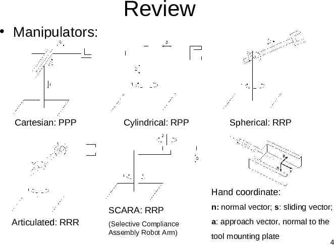
Review Manipulators: Cartesian: PPP Cylindrical: RPP Spherical: RRP Hand coordinate: Articulated: RRR SCARA: RRP n: normal vector; s: sliding vector; (Selective Compliance Assembly Robot Arm) a: approach vector, normal to the tool mounting plate 4
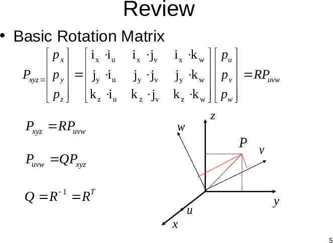
Review Basic Rotation Matrix p x i x i u Pxyz p y jy i u p z k z i u Pxyz RPuvw i x jv jy jv k z jv i x k w pu jy k w pv RPuvw k z k w pw z w P v Puvw QPxyz Q R 1 R T u y x 5
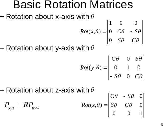
Basic Rotation Matrices – Rotation about x-axis with 1 0 Rot ( x, ) 0 C 0 S 0 S C – Rotation about y-axis with C Rot ( y, ) 0 S – Rotation about z-axis with Pxyz RPuvw C Rot ( z , ) S 0 0 S 1 0 0 C S C 0 0 0 1 6
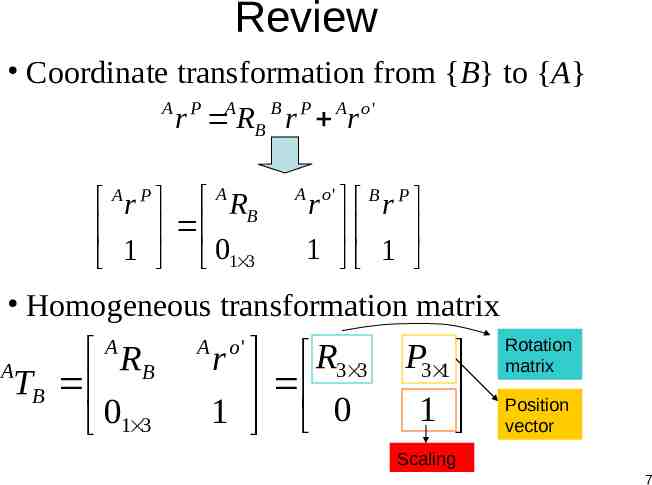
Review Coordinate transformation from {B} to {A} A P r ARB B r P Ar o ' A r P A RB 1 01 3 A o' B P r r 1 1 Homogeneous transformation matrix A RB TB 01 3 A A o' r R3 3 1 0 P3 1 1 Rotation matrix Position vector Scaling 7
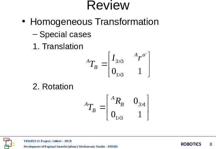
Review Homogeneous Transformation – Special cases 1. Translation I 3 3 A TB 01 3 A o' A RB A TB 01 3 03 1 1 r 1 2. Rotation TEMPUS IV Project: 158644 – JPCR Development of Regional Interdisciplinary Mechatronic Studies - DRIMS ROBOTICS 8
Review Composite Homogeneous Transformation Matrix Rules: – Transformation (rotation/translation) w.r.t. (X,Y,Z) (OLD FRAME), using pre-multiplication – Transformation (rotation/translation) w.r.t. (U,V,W) (NEW FRAME), using postmultiplication TEMPUS IV Project: 158644 – JPCR Development of Regional Interdisciplinary Mechatronic Studies - DRIMS ROBOTICS 9
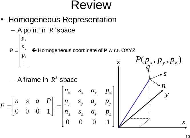
Review Homogeneous Representation – A point in R 3 space px p P y Homogeneous coordinate of P w.r.t. OXYZ pz P( p x , z 1 a – A frame in R space 3 n s a P F 0 0 0 1 nx n y nz 0 sx sy sz 0 ax ay az 0 px p y pz 1 p y , pz ) s n y x 10
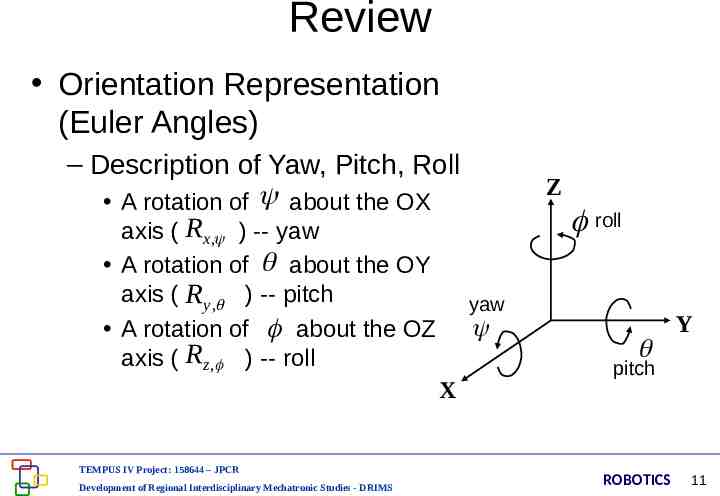
Review Orientation Representation (Euler Angles) – Description of Yaw, Pitch, Roll A rotation of about the OX axis ( Rx , ) -- yaw A rotation of about the OY axis ( R y , ) -- pitch yaw A rotation of about the OZ axis ( Rz , ) -- roll X TEMPUS IV Project: 158644 – JPCR Development of Regional Interdisciplinary Mechatronic Studies - DRIMS Z roll Y pitch ROBOTICS 11
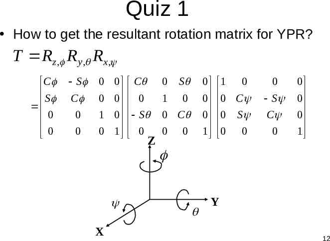
Quiz 1 How to get the resultant rotation matrix for YPR? T Rz , R y , Rx , C S 0 0 S C 0 0 0 0 0 0 1 0 0 1 C 0 S 0 Z 0 S 1 0 0 0 0 1 0 C 0 0 1 0 0 C 0 S 0 0 0 S C 0 0 0 0 1 X Y 12
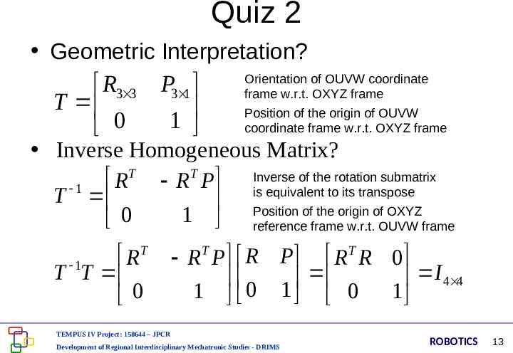
Quiz 2 Geometric Interpretation? R3 3 T 0 P3 1 1 Orientation of OUVW coordinate frame w.r.t. OXYZ frame Position of the origin of OUVW coordinate frame w.r.t. OXYZ frame Inverse Homogeneous Matrix? T T Inverse of the rotation submatrix R R P 1 is equivalent to its transpose T Position of the origin of OXYZ 1 reference frame w.r.t. OUVW frame 0 T R T 1T 0 R T P R P R T R 0 I 4 4 1 0 1 0 1 TEMPUS IV Project: 158644 – JPCR Development of Regional Interdisciplinary Mechatronic Studies - DRIMS ROBOTICS 13
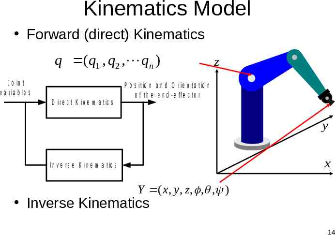
Kinematics Model Forward (direct) Kinematics q (q1 , q2 , qn ) J o in t v a r ia b le s D ir e c t K in e m a t ic s z P o s it io n a n d O r ie n t a t io n o f th e e n d -e ffe c to r y x I n v e r s e K in e m a t ic s Y ( x, y, z , , , ) Inverse Kinematics 14
Robot Links and Joints TEMPUS IV Project: 158644 – JPCR Development of Regional Interdisciplinary Mechatronic Studies - DRIMS ROBOTICS 15
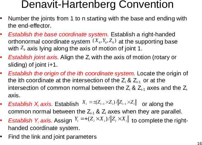
Denavit-Hartenberg Convention Number the joints from 1 to n starting with the base and ending with the end-effector. Establish the base coordinate system. Establish a right-handed orthonormal coordinate system ( X 0 , Y0 , Z 0 ) at the supporting base with Z 0 axis lying along the axis of motion of joint 1. Establish joint axis. Align the Zi with the axis of motion (rotary or sliding) of joint i 1. Establish the origin of the ith coordinate system. Locate the origin of the ith coordinate at the intersection of the Zi & Zi-1 or at the intersection of common normal between the Zi & Zi-1 axes and the Zi axis. Establish Xi axis. Establish X i ( Z i 1 Z i ) / Z i 1 Z i or along the common normal between the Zi-1 & Zi axes when they are parallel. Establish Yi axis. Assign Yi ( Z i X i ) / Z i X i to complete the righthanded coordinate system. Find the link and joint parameters 16
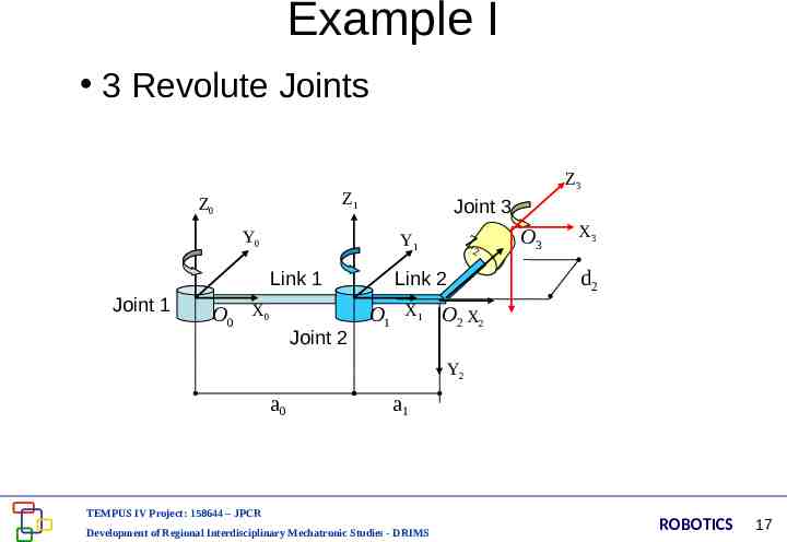
Example I 3 Revolute Joints Z1 Z0 Y0 Joint 3 Y1 Link 1 Joint 1 Z3 O0 X0 Joint 2 Z 2 O3 X3 d2 Link 2 O1 X1 O2 X2 Y2 a0 a1 TEMPUS IV Project: 158644 – JPCR Development of Regional Interdisciplinary Mechatronic Studies - DRIMS ROBOTICS 17
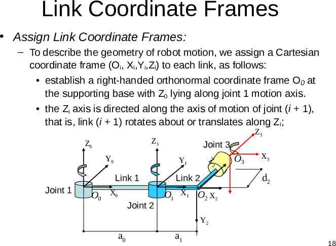
Link Coordinate Frames Assign Link Coordinate Frames: – To describe the geometry of robot motion, we assign a Cartesian coordinate frame (Oi, Xi,Yi,Zi) to each link, as follows: establish a right-handed orthonormal coordinate frame O0 at the supporting base with Z0 lying along joint 1 motion axis. the Zi axis is directed along the axis of motion of joint (i 1), that is, link (i 1) rotates about or translates along Zi; Z1 Z0 Y0 Joint 3 Y1 Link 1 Joint 1 Z3 O0 X0 Joint 2 Z 2 O3 X3 d2 Link 2 O1 X1 O2 X2 Y2 a0 a1 18
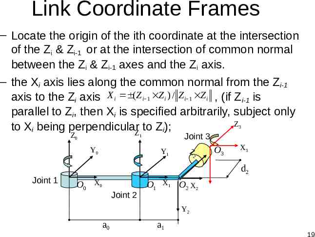
Link Coordinate Frames – Locate the origin of the ith coordinate at the intersection of the Zi & Zi-1 or at the intersection of common normal between the Zi & Zi-1 axes and the Zi axis. – the Xi axis lies along the common normal from the Zi-1 axis to the Zi axis X i ( Z i 1 Z i ) / Z i 1 Z i , (if Z i-1 is parallel to Zi, then Xi is specified arbitrarily, subject only Z to Xi being perpendicularZ to Zi); 3 Z0 Y0 Joint 1 Joint 3 1 Y1 Z 2 O3 X3 d2 O0 X0 Joint 2 O1 X1 O2 X2 Y2 a0 a1 19
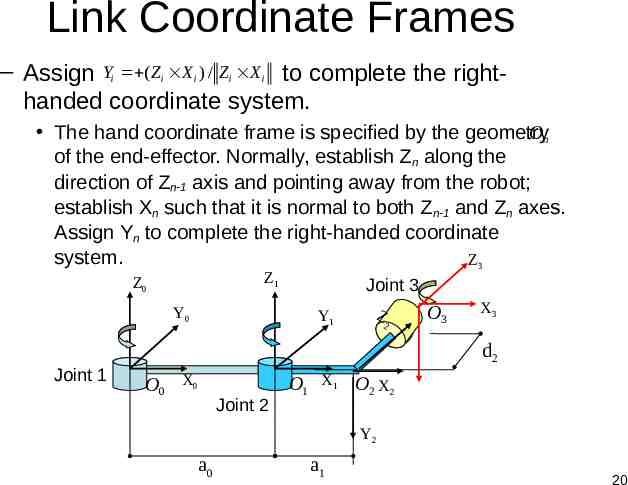
Link Coordinate Frames – Assign Yi ( Z i X i ) / Z i X i to complete the righthanded coordinate system. The hand coordinate frame is specified by the geometry On of the end-effector. Normally, establish Zn along the direction of Zn-1 axis and pointing away from the robot; establish Xn such that it is normal to both Zn-1 and Zn axes. Assign Yn to complete the right-handed coordinate system. Z3 Z1 Z0 Y0 Joint 1 Joint 3 Y1 Z 2 O3 X3 d2 O0 X0 Joint 2 O1 X1 O2 X2 Y2 a0 a1 20
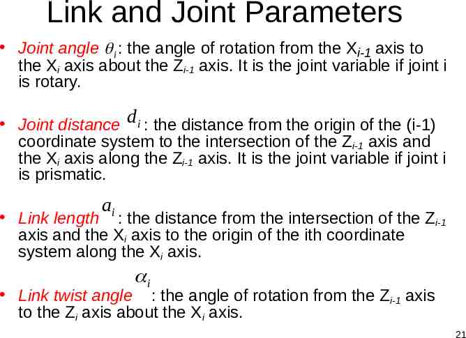
Link and Joint Parameters Joint angle i : the angle of rotation from the Xi-1 axis to the Xi axis about the Zi-1 axis. It is the joint variable if joint i is rotary. Joint distance d i : the distance from the origin of the (i-1) coordinate system to the intersection of the Zi-1 axis and the Xi axis along the Zi-1 axis. It is the joint variable if joint i is prismatic. ai Link length : the distance from the intersection of the Zi-1 axis and the Xi axis to the origin of the ith coordinate system along the Xi axis. i Link twist angle : the angle of rotation from the Zi-1 axis to the Zi axis about the Xi axis. 21
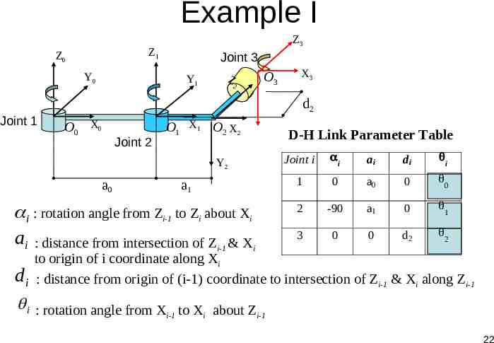
Example I Z1 Z0 Y0 Joint 1 Z3 Joint 3 Y1 Z 2 O3 d2 O0 X0 Joint 2 O1 X1 O2 X2 Y2 a0 a1 i : rotation angle from Zi-1 to Zi about Xi ai : distance from intersection of Zi-1 & Xi di X3 D-H Link Parameter Table Joint i i ai di i 1 0 a0 0 0 2 -90 a1 0 1 3 0 0 d2 2 to origin of i coordinate along Xi : distance from origin of (i-1) coordinate to intersection of Zi-1 & Xi along Zi-1 i : rotation angle from X to X about Z i-1 i i-1 22
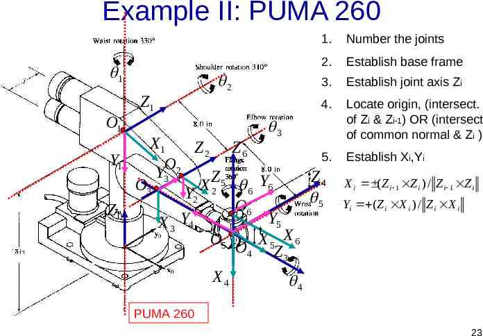
Example II: PUMA 260 1 O1 Z1 2 3 1. Number the joints 2. Establish base frame 3. Establish joint axis Zi 4. Locate origin, (intersect. of Zi & Zi-1) OR (intersect of common normal & Zi ) X1 Z2 Z6 5. Y1 O2 Y3 Z Z4 O3 X 2 5 6 Y6 Y2 5 O Z0 6 Y Y5 X3 4 t O5 X5 X6 O4 Z 3 X4 Establish Xi,Yi X i ( Z i 1 Z i ) / Z i 1 Z i Yi ( Z i X i ) / Z i X i 4 PUMA 260 23
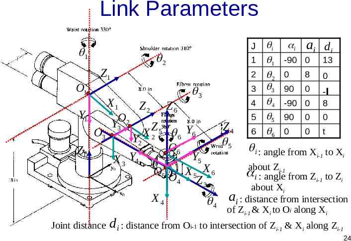
Link Parameters J 1 O1 Z1 2 1 2 3 3 X1 Z2 Z6 Y1 O Y3 2 Z Z4 O3 X 2 5 6 Y6 Y2 5 O Z0 6 Y Y5 X3 4 O5 X5 X6 O4 Z 3 X4 Joint distance 4 4 5 6 i 1 2 3 4 5 6 i ai d i -90 0 13 0 8 0 90 0 -90 0 -l 8 90 0 0 0 0 t i : angle from X to X i-1 i Zi-1 about i : angle from Zi-1 to Zi about Xi ai : distance from intersection of Zi-1 & Xi to Oi along Xi d i : distance from Oi-1 to intersection of Zi-1 & Xi along Zi-1 24
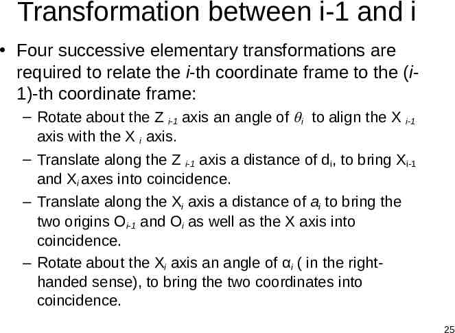
Transformation between i-1 and i Four successive elementary transformations are required to relate the i-th coordinate frame to the (i1)-th coordinate frame: – Rotate about the Z i-1 axis an angle of i to align the X i-1 axis with the X i axis. – Translate along the Z i-1 axis a distance of di, to bring Xi-1 and Xi axes into coincidence. – Translate along the Xi axis a distance of ai to bring the two origins Oi-1 and Oi as well as the X axis into coincidence. – Rotate about the Xi axis an angle of αi ( in the righthanded sense), to bring the two coordinates into coincidence. 25
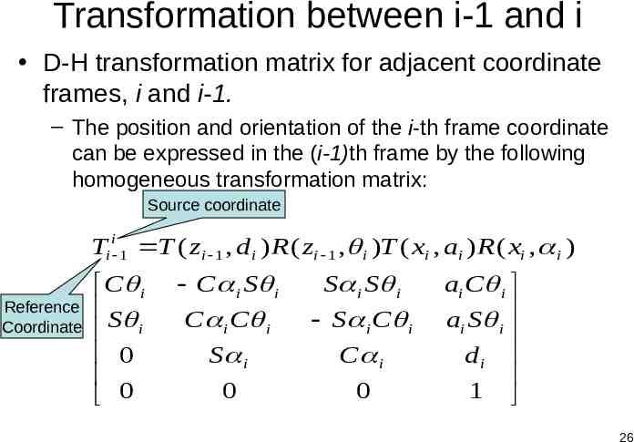
Transformation between i-1 and i D-H transformation matrix for adjacent coordinate frames, i and i-1. – The position and orientation of the i-th frame coordinate can be expressed in the (i-1)th frame by the following homogeneous transformation matrix: Source coordinate Ti i 1 T ( zi 1 , d i ) R ( zi 1 , i )T ( xi , ai ) R ( xi , i ) Reference Coordinate C i S i 0 0 C i S i C i C i S i S i S i S i C i C i 0 0 ai C i ai S i di 1 26
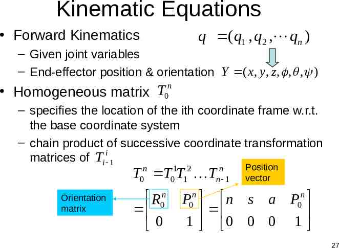
Kinematic Equations Forward Kinematics q (q1 , q2 , qn ) – Given joint variables – End-effector position & orientation Y ( x, y, z , , , ) Homogeneous matrix T0n – specifies the location of the ith coordinate frame w.r.t. the base coordinate system – chain product of successive coordinate transformation i matrices of Ti 1 n 0 1 2 0 1 n n 1 T T T T Orientation matrix R0n 0 Position vector P0n n s a P0n 1 0 0 0 1 27
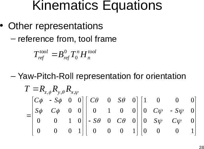
Kinematics Equations Other representations – reference from, tool frame 0 Treftool Bref T0n H ntool – Yaw-Pitch-Roll representation for orientation T Rz , R y , Rx , C S 0 0 S C 0 0 0 0 0 0 1 0 0 1 C 0 S 0 0 S 1 0 0 C 0 0 0 0 0 1 1 0 0 C 0 S 0 0 0 S C 0 0 0 0 1 28
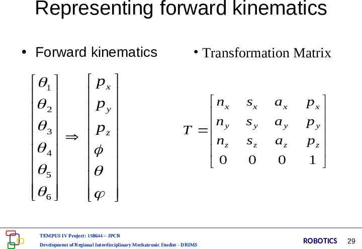
Representing forward kinematics Forward kinematics px 1 p y 2 pz 3 4 5 6 Transformation Matrix nx n T y nz 0 TEMPUS IV Project: 158644 – JPCR Development of Regional Interdisciplinary Mechatronic Studies - DRIMS sx sy sz 0 ax ay az 0 px p y pz 1 ROBOTICS 29
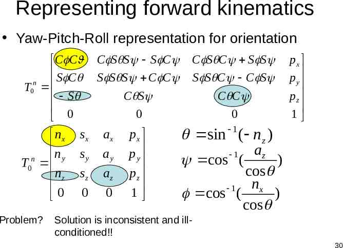
Representing forward kinematics Yaw-Pitch-Roll representation for orientation C C S C T0n S 0 nx n T0n y nz 0 Problem? C S S S C S S S C C C S 0 sx ax sy ay sz 0 az 0 px p y pz 1 C S C S S S S C C S C C 0 px p y pz 1 sin 1 ( nz ) az cos ( ) cos nx 1 cos ( ) cos 1 Solution is inconsistent and illconditioned!! 30
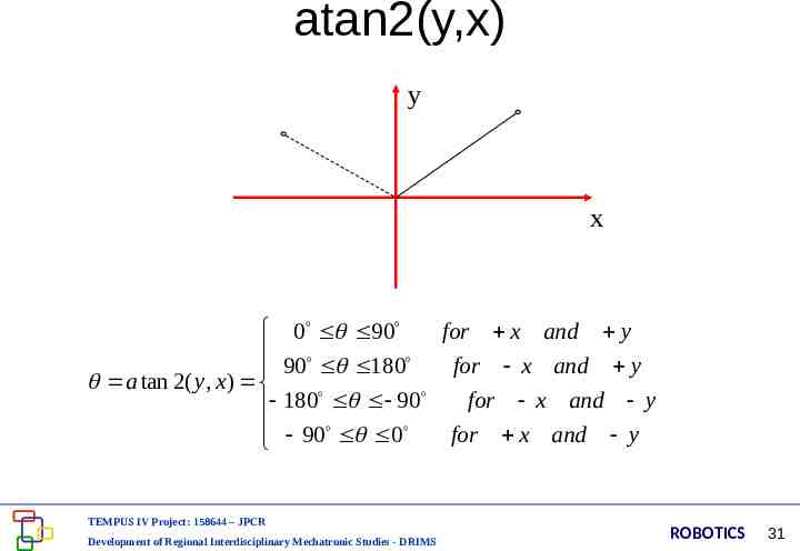
atan2(y,x) y x 0 90 for x and y for x and y 90 180 a tan 2( y, x) 180 90 for x and y 90 0 for x and y TEMPUS IV Project: 158644 – JPCR Development of Regional Interdisciplinary Mechatronic Studies - DRIMS ROBOTICS 31
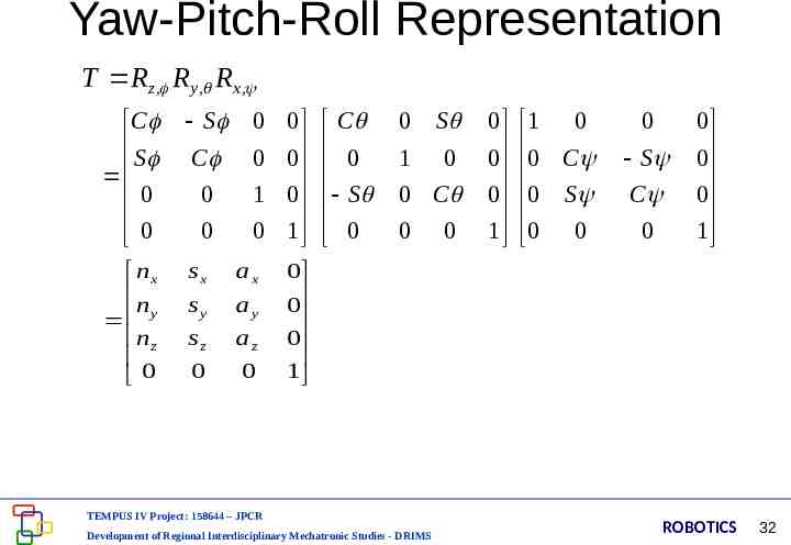
Yaw-Pitch-Roll Representation T Rz , R y , Rx , C S 0 0 S nx n y nz 0 sx ax sy ay sz az 0 0 C 0 0 0 0 0 0 1 0 0 1 C 0 S 0 0 S 1 0 0 C 0 0 0 0 0 1 1 0 0 C 0 S 0 0 0 S C 0 0 0 0 1 0 0 0 1 TEMPUS IV Project: 158644 – JPCR Development of Regional Interdisciplinary Mechatronic Studies - DRIMS ROBOTICS 32
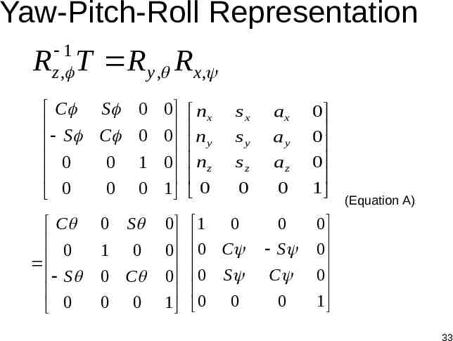
Yaw-Pitch-Roll Representation 1 z , R T R y , Rx , C S 0 0 C 0 S 0 S C 0 0 0 1 0 0 1 0 0 0 0 1 nx n y nz 0 S 0 0 0 0 1 0 C 0 0 sx sy sz ax ay az 0 0 1 0 0 C 0 S 0 0 0 S C 0 0 0 0 1 (Equation A) 0 0 0 1 33
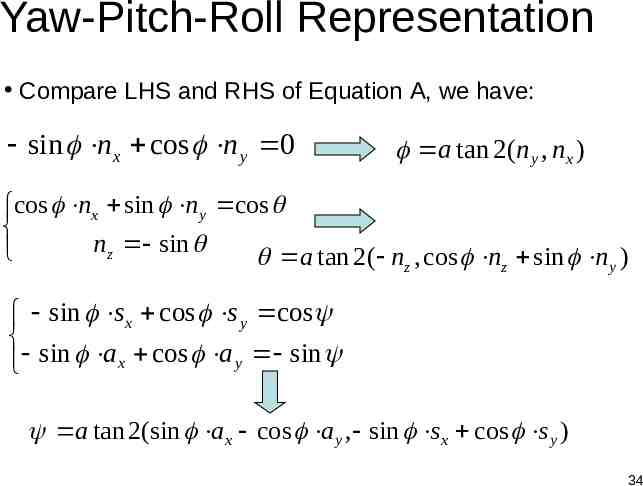
Yaw-Pitch-Roll Representation Compare LHS and RHS of Equation A, we have: sin nx cos n y 0 a tan 2(n y , nx ) cos nx sin n y cos nz sin a tan 2( nz , cos nz sin n y ) sin s x cos s y cos sin a x cos a y sin a tan 2(sin a x cos a y , sin s x cos s y ) 34
Kinematic Model Steps to derive kinematics model: – Assign D-H coordinates frames – Find link parameters – Transformation matrices of adjacent joints – Calculate Kinematics Matrix – When necessary, Euler angle representation TEMPUS IV Project: 158644 – JPCR Development of Regional Interdisciplinary Mechatronic Studies - DRIMS ROBOTICS 35
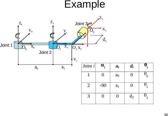
Example Z1 Z0 Y0 Joint 1 Z3 Joint 3 Y1 Z 2 O3 X3 d2 O0 X0 Joint 2 O1 X1 O2 X2 Y2 a0 a1 Joint i i ai di i 1 0 a0 0 0 2 -90 a1 0 1 3 0 0 d2 2 36
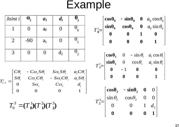
Example Joint i i ai di i 1 0 a0 0 0 2 -90 a1 0 1 3 0 0 d2 2 i i 1 T C i S i 0 0 C i S i C i C i S i 0 S i S i S i C i C i 0 T03 (T 01)(T 21)(T 23) ai C i ai S i di 1 cosθ 0 1 sinθ 0 T 0 0 0 cosθ1 2 sinθ1 T 1 0 0 cosθ 2 3 sin 2 T 2 0 0 sinθ 0 0 a0 cos 0 0 a0 sin 0 1 0 0 1 cosθ 0 0 0 0 sin 1 0 1 cos 1 0 0 0 sinθ 2 cos 2 0 0 a1 cos 1 a1 sin 1 0 1 0 0 0 0 1 d2 0 1 37
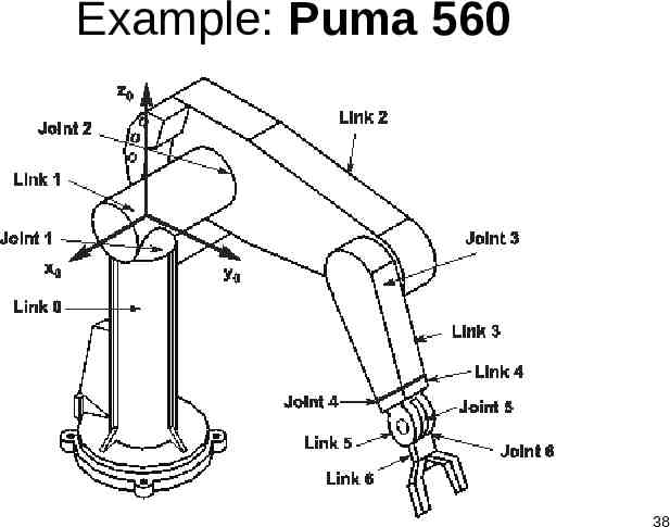
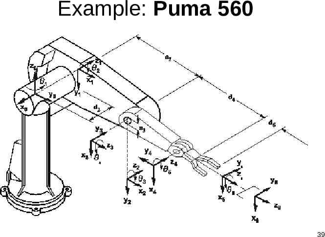
Example: Puma 560 38
Example: Puma 560 39
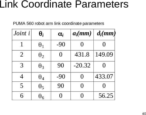
Link Coordinate Parameters PUMA 560 robot arm link coordinate parameters Joint i i i ai(mm) di(mm) 1 1 -90 2 2 0 431.8 149.09 3 3 90 -20.32 0 4 5 4 5 -90 90 0 0 433.07 0 6 6 0 0 56.25 0 0 40
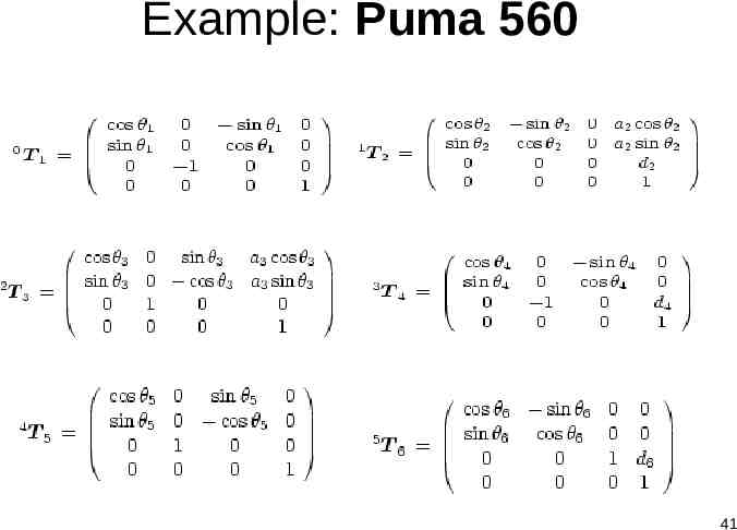
Example: Puma 560 41
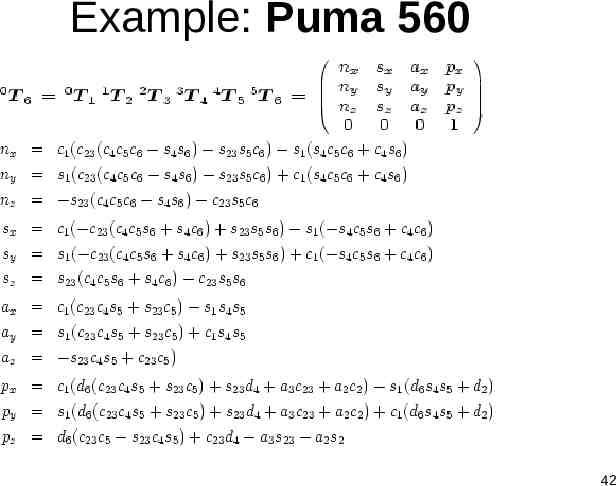
Example: Puma 560 42
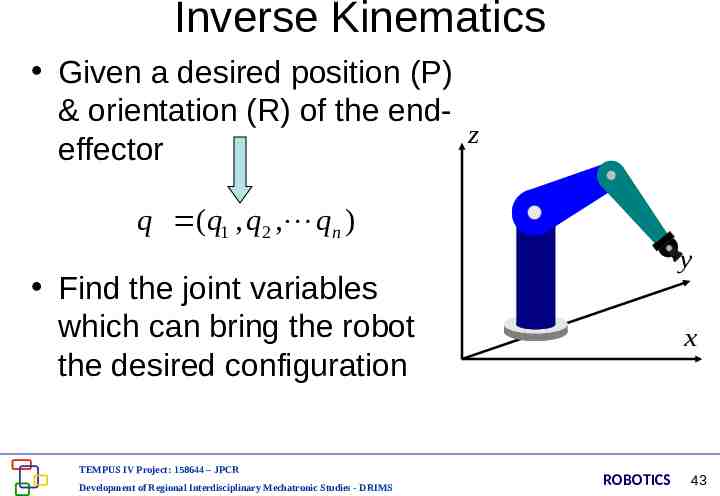
Inverse Kinematics Given a desired position (P) & orientation (R) of the endz effector q (q1 , q2 , qn ) y Find the joint variables which can bring the robot the desired configuration TEMPUS IV Project: 158644 – JPCR Development of Regional Interdisciplinary Mechatronic Studies - DRIMS x ROBOTICS 43
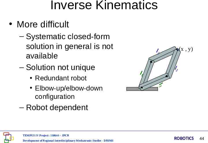
Inverse Kinematics More difficult – Systematic closed-form solution in general is not available – Solution not unique l2 l1 l1 Redundant robot Elbow-up/elbow-down configuration (x , y) l2 – Robot dependent TEMPUS IV Project: 158644 – JPCR Development of Regional Interdisciplinary Mechatronic Studies - DRIMS ROBOTICS 44
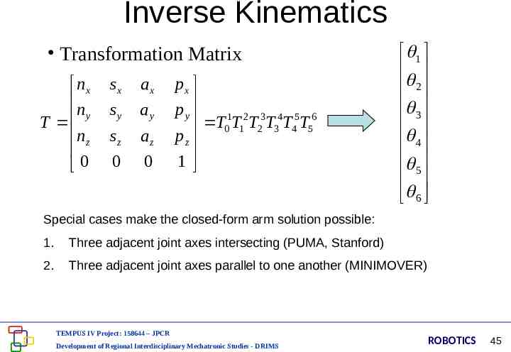
Inverse Kinematics Transformation Matrix nx n T y nz 0 sx ax sy ay sz az 0 0 px p y T01T12T23T34T45T56 pz 1 1 2 3 4 5 6 Special cases make the closed-form arm solution possible: 1. Three adjacent joint axes intersecting (PUMA, Stanford) 2. Three adjacent joint axes parallel to one another (MINIMOVER) TEMPUS IV Project: 158644 – JPCR Development of Regional Interdisciplinary Mechatronic Studies - DRIMS ROBOTICS 45
Literature: J.M. Selig: Introductory Robotics, Prentice Hall, 1992: - Chapter 4, Kinematics, pp.34-43, - Chapter 5, Inverse Kinematics, pp.44-58 TEMPUS IV Project: 158644 – JPCR Development of Regional Interdisciplinary Mechatronic Studies - DRIMS ROBOTICS 46