PHILOSOPHY OF LIMIT STATE DESIGN AND CLASSIFICATION OF SECTIONS Dr.


96 Slides834.00 KB
PHILOSOPHY OF LIMIT STATE DESIGN AND CLASSIFICATION OF SECTIONS Dr. M. R. Shiyekar Sinhgad College of Engineering, Pune
What is Limit State? Acceptable limit for the safety and serviceability requirements before failure occurs is called a Limit state
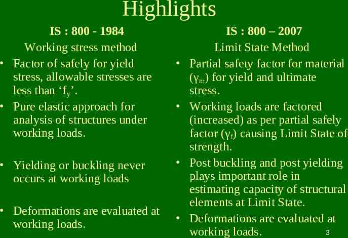
Highlights IS : 800 - 1984 Working stress method Factor of safely for yield stress, allowable stresses are less than ‘fy’. Pure elastic approach for analysis of structures under working loads. Yielding or buckling never occurs at working loads Deformations are evaluated at working loads. IS : 800 – 2007 Limit State Method Partial safety factor for material (γm) for yield and ultimate stress. Working loads are factored (increased) as per partial safely factor (γf) causing Limit State of strength. Post buckling and post yielding plays important role in estimating capacity of structural elements at Limit State. Deformations are evaluated at 3 working loads.
Classification of cross sections Structural elements in axial compression, bending compression tend to buckle prior yielding. To avoid this, elements of cross section such as width of flange, depth of web of I and channel section, width of legs of angle section, width of flange and leg of Tee section, width and height of Box section need to be proportioned in relation with thickness of element of section. 4
Classification of cross sections A table of classification shows three distinct varieties of cross section such as plastic, compact and semi compact section. Section in which width to thickness ratio exceeds the limits of semi compact section is known as slender section. These sections are to be avoided. Slender section if at all used needs to ignore excess area to arrive at effective cross section as semi compact section. If two elements of cross section fall under two different classifications then section is classified into most unfavourable classification. 5
Elements of cross section 6
Elements of cross section 7
8
9
Classification of section 10
Classification of section CONTD 11
Table showing various γf factors for Limit States 12
Table showing Partial safety factors for materials γm 13
THE END 14
DESIGN OF FLEXURAL MEMBER AND BENDING WITH HIGH SHEAR Dr. M. R. Shiyekar Sinhgad College of Engineering, Pune 15
16
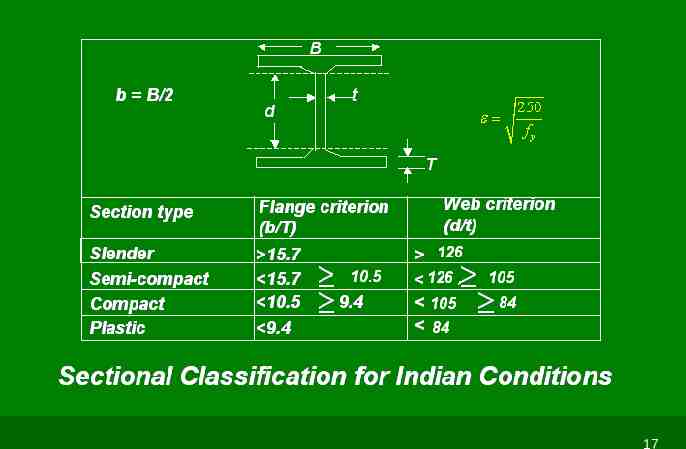
17
Flexural members Laterally supported beam Elastic Analysis Me 0.66 fy.Ze Plastic Analysis fy Md b Zp mo When factored design shear 0.6Vd and d 67 tw 18
Conditions to Qualify as a Laterally Restrained Beam It should not laterally buckle None of its element should buckle until a desired limit state is achieved Limit state of serviceability must be satisfied Member should behave in accordance with the expected performance of the system 19
Lateral Stability of Beams 20
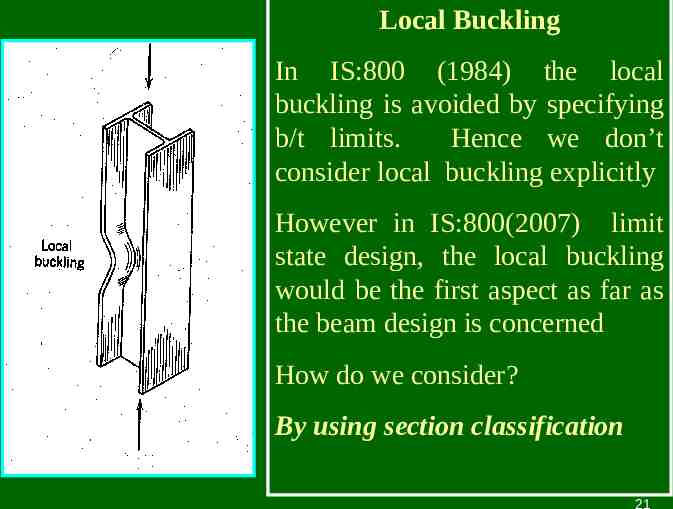
Local Buckling In IS:800 (1984) the local buckling is avoided by specifying b/t limits. Hence we don’t consider local buckling explicitly However in IS:800(2007) limit state design, the local buckling would be the first aspect as far as the beam design is concerned How do we consider? By using section classification 21
Limit states for LR beams Limit state of flexure Limit state of shear Limit state of bearing Limit state of serviceability 22
f Stress fy 1 Plastic range Elastic range 2 3 4 Idealised stress strain curve strain Idealized elasto- plastic stress stain curve for the purpose of design 23
W 1 2 3 4 Plastic Hinge Simply supported beam and its deflection at various stages 24
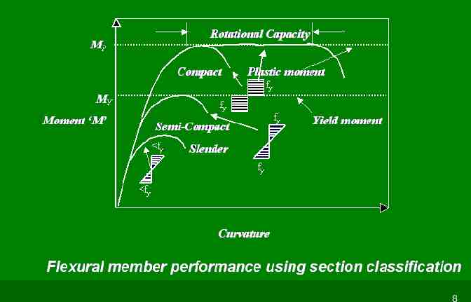
Moment ‘M’ MP MY Plastic moment Effect of strain hardening may occur after large rotation Yield moment Curvature Moment curvature characteristics of the simply supported beam 25
Some typical shape factor 2.0 1.27 1.5 1.7 1.14 26
EQUATIONS FOR SHEAR CAPACITY y fy 3 0.577 f y Vp f ytwd w / 3 Vp Vd mo 27
Shear yielding near support Web buckling Web crippling 28
Pwb ( b1 n1 ) t f c d/2 b1 n1 450 d/2 L 0.7 d E ry ry ry t3 t A 12t 2 3 Iy LE 2 3 d 0.7 d 2.5 ry t t Effective width for web buckling 29
30
Pcrip ( b1 n2 ) t f yw b1 n2 Effective width of web bearing 1:2.5 slope Root radius Web Crippling in beams 31
Design of Laterally Supported Beam Limit State Method – As per IS: 800 - 2007. Example No : 1 Design a suitable I beam for a simply supported span of 5 m. and carrying a dead load of 20 kN/m and imposed load of 40 kN/m. Take fy 250 MPa Design load calculations : Factored load γLD x 20 γLL x 40 Using partial safety factors for D.L γLD 1.50 and for L.L γLL 1.5 (Cl. 5.3.3 Table 4, Page 29) 32
Total factored load 1.50 x 20 1.5 x 40 90 kN/m Factored Bending Moment M 90 x 5 x 5 / 8 281.25 kN.m Zp required for value of fy 250 MPa and γmo 1.10 (Table 5, Page 30) Zp (281.25 x 1000 x 1000 x 1.1) / 250 1237500 mm3 1237.50cm3 Using shape factor 1.14, Ze 1237.50/1.14 1085.52 cm3 Options ISWB 400 @ 66.7 kg/m or ISLB 450 @ 65.3 kg/m Try ISLB 450 Ze 1223.8 cm3 1085.52 33
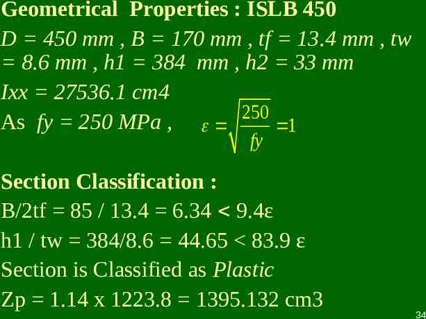
Geometrical Properties : ISLB 450 D 450 mm , B 170 mm , tf 13.4 mm , tw 8.6 mm , h1 384 mm , h2 33 mm Ixx 27536.1 cm4 As fy 250 MPa , 250 1 fy Section Classification : B/2tf 85 / 13.4 6.34 9.4ε h1 / tw 384/8.6 44.65 83.9 ε Section is Classified as Plastic Zp 1.14 x 1223.8 1395.132 cm3 34
Design Bending Strength: Md b Z p fy 1.0 x1395.132 x1000 x 250 Md 317.075 kN .m mo 1.10 281.25 kN.m βb 1.0 for plastic section (Cl. 8.2.1.2, Page 53) Check for Serviceability – Deflection Load factor γLD and γLL 1.00 both , (Cl. 5.6.1, Page 31) Design load 20 40 60 kN/m 35
5 x60 x(5000) 4 8.866 mm 5 4 384 x 2 x10 x 27536.1 x10 Limiting deflection Span/360 (Table. 5.3, Page 52) 5000/360 13.889 mm .OK Hence Use ISLB 450 36
Working Stress Method IS : 800 - 1984 Max Bending Moment 60 x 5 x 5/8 187.5 kN.m Max Shear Force 60 x 5/2 150 kN 187.5 x10⁶ 3 Zreq 1136.3 cm 165 Select ISLB 450 Zxx 1223.8 Moment Capacity 201.927 kN.m Check for Shear 150 x1000 qav 38.76 MPa 100 MPa 450 x8.6 37
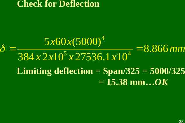
Check for Deflection 4 5 x60 x(5000) 8.866 mm 5 4 384 x 2 x10 x 27536.1 x10 Limiting deflection Span/325 5000/325 15.38 mm OK 38
Comparison of ISLB 450 Section Working Stress Method Limit State Method Moment 201.927 kN.m Capacity 187.5 KNm 317.075 KNm 281.25 KNm Shear 387 KN 150 KN Capacity 507.497KN 225 KN Section ISLB 450@ 65.3 Designed Kg/m ISLB 450 @ 65.3 kg/m The Section designed as per LSM is having more reserve capacity for both BM and SF as compared to WSM 39
Design of Beam with High Shear LSM Example No. 2 Factored Load 100 KN/m A B C 5m 5m 40
Plastic Analysis Degree of Redundancy r 1 No. of plastic hinges required to transform structure into mechanism r 1 2 Failure of any span is failure of continuous beam. Failure mechanism of AB & BC is identical due to symmetry & this is similar to failure mechanism of propped cantilever beam with udl. wp 11.656 Mp / l2 Mp wp.l2 / 11.656 100 x 25 / 11.656 214.48 KNm. 41
As both spans fail simultaneously actual no of plastic hings are three – two hinges each at 0.414 l from A & C & third at B. as n 3 2 required Collapse is over complete Zp 214.48 x 106 x 1.10 / 250 mm3 943.72 cm3 Ze 943.72 / 1.14 827. 82 cm3 Select ISLB 400 Zxx 965.3 cm3 Md 1.0 x 1.14 x 965.3 x 250 / 1.10 250.1 KNm 214.48 42
Reaction at A Considering free body of AB Mp 214.48 KNm Mp RA x 5 100 x 5 x 5/2 RA 207.1 KN RB1 500 – 207.1 292.9 KN Due to symmetry in loading Maximum shear is at B 292.9 KN V 43
Vd 0.577 x 400 x 8 x 250 / 1.1 419.636 KN Where 400 x 8 D.tw of ISLB 400 As V/Vd 292.9 / 419.636 0.697 0.6 As per C1.9.2.2 Page No. 70 Effect of shear is to be considered for reduction in moment capacity Mdv Md – β(Md – Mfd) β (2V/Vd – 1)2 0.156 Mfd Plastic moment capacity of flanges only 165 x 12.5 (400 – 12.5) x 250 / 1.1 181.64 KNm Mdv 250.1 – 0.156 (250.1 – 181.64) 239.42 KNm As Mdv 239.42 Mp 214.48 ------- Ok Select ISLB 400 @ 56.9 kg / m 44
Laterally supported beam Design of Beams with High Shear by WSM Factored load in LSM is 100 KN/m Working load in WSM 100 / 1.5 66.67 KN/m 66.67 KN/m A 5m B 5m C 45
Reactions RB 5/8 x 66.67 x 10 416.66 kN , RA RC 125.0 kN Maximum Bending Moment At continuous support 125.0 x 5 – 66.67 x 5 x 5/2 -208.33 kN.m Design Shear 208.33 kN Design Moment 208.33 kN.m As per IS:800 – 1984, 6bc 0.66fy 0.66 x 250 165 MPa Z required (208.33 x 10⁶) / 165 1262.62 cm3 Try ISMB 450 @ 72.4 kg/m. Zxx 1350 cm2 1262.62 Cheak for shear tw 9.4 mm qav (208.33 x 1000) / (450 x 9.4) 49.25 N/mm2 0.4fy i.e. 100 N/mm2 46
Comparison of WSM vs LSM Working Stress Method Limit State Method Moment Capacity 222.75 KNm 208.33 KNm 239.42 KNm 214.48 Shear Capacity 423 KN 208.33 KN 419.636 KN 292.90 KN Section Designed ISMB 450 @ 72.4 kg/m ISLB 400 @ 56.9 kg/m Design of beam by LSM is more economical 47
THE END 48
DESIGN OF GANTRY GIRDER Dr. M. R. Shiyekar Sinhgad College of Engineering, Pune 49
FEATURES Design of Gantry Girder is a classic example of laterally unsupported beam. It is subjected to in addition to vertical loads horizontal loads along and perpendicular to its axis. Loads are dynamic which produces vibration. Compression flange requires critical attention. 50
IS:800-2007 PROVISIONS Partial safety factor for both dead load and crane load is 1.5 (Table 4, p. no. 29). Partial safety factor for serviceability for both dead load and crane load is 1.0 (Table 4, p. no. 29). Deflection limitations (Table 6, p. no. 31). Vertical loads i) Manually operated Span/500 ii) Electric operated. Span/750 up to 50t iii) Electric operated Span/1000 over 50t 51
OTHER CONSIDERATIONS Diaphragm must be provided to connect compression flange to roof column of industrial building to ensure restraint against lateral torsional buckling. Span is considered to be simply supported to avoid bumpy effect. 52
53
54
TYPICAL GANTRY GIRDER DETAILS 55
FORCES AND MOTIONS 56
VARIOUS TYPES OF SUPPORTS 57
58
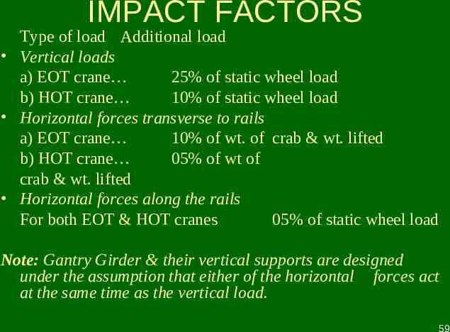
IMPACT FACTORS Type of load Additional load Vertical loads a) EOT crane 25% of static wheel load b) HOT crane 10% of static wheel load Horizontal forces transverse to rails a) EOT crane 10% of wt. of crab & wt. lifted b) HOT crane 05% of wt of crab & wt. lifted Horizontal forces along the rails For both EOT & HOT cranes 05% of static wheel load Note: Gantry Girder & their vertical supports are designed under the assumption that either of the horizontal forces act at the same time as the vertical load. 59
GANTRY GIRDER DESIGN Data a) Wt. of crane girder/truss b) Crane capacity c) Wt. of crab motor d) Span of crane girder/truss e) Min hook approach f) c/c distance betn grantry columns g) Wt. of rail 180kN 200kN 50kN 16m 1.2m 6m 0.25kN/m 60
Maximum vertical static wheel load RA/2 160.625 kN 61
Wheel load with impact 1.25 X 160.625 200.775 kN Factored load 1.5 X 200.775 301.16 kN Absolute max bending moment in Gantry Girder This will occur under any wheel load when distance betn that load and C.G. of load system is equidistant from the centre of the Gantry Girder span. 62
Absolute max bending moment 508.21 kNm Md Design moment for laterally unsupported beam βb . Zp . fbd (Clause 8.2.2, p. no. 54) Where βb 1.0 for plastic section (assumed) Zp plastic modulus of section fbd design bending compressive stress 63
Assuming fbd 200 Mpa Zp required (508.21 X 10⁶) / (1.0 X 200) 2.54 X 106 mm3 Using I and channel section and assuming 80% of Zp is contributed by I section Zp by I section 2.032 X 106 mm3 using shape factor of I section 1.14 Ze required 2032 / 1.14 1766.95 cm3 select ISWB 500 @ 0.94 kN/m Ze provided 2091.6 1766.95 cm3 . OK 64
Width of the flange of ISWB 500 250 mm Select channel section having clear web depth more than 250 mm. Select ISLC 350 @ 0.38 kN/m having h1 291.9 mm 250 mm . OK Total dead load intensity 0.94 0.38 0.25 1.57 kN/m Factored dead load intensity 1.5 X 1.57 2.355 kN/m Bending moment @ E 9.93 kNm Total bending moment due to DL CL 518.14 kNm 65
SELECTED CROSS SECTION 66
Refer Annexure E (p. no. 128) Elastic lateral torsional buckling moment Elastic critical moment of a section symmetrical about minor axis yy is given by E-1.2 of Annexure E (p. no. 128) in which various factors and geometrical values of Gantry Girder section are involved. 67
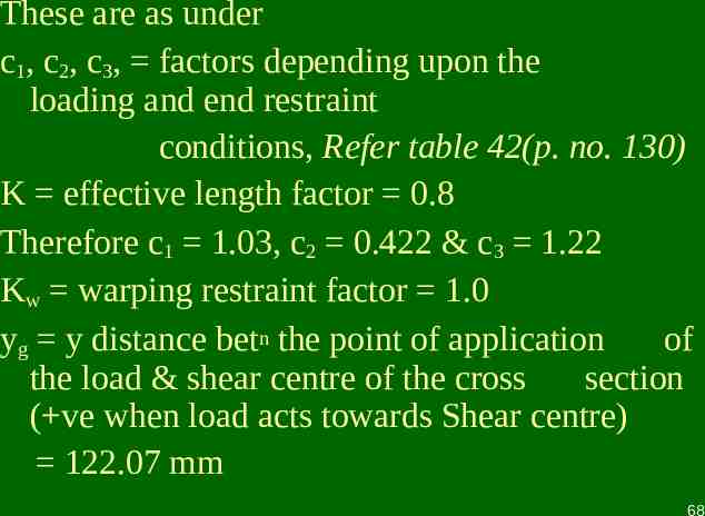
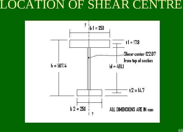
These are as under c1, c2, c3, factors depending upon the loading and end restraint conditions, Refer table 42(p. no. 130) K effective length factor 0.8 Therefore c1 1.03, c2 0.422 & c3 1.22 Kw warping restraint factor 1.0 yg y distance betn the point of application of the load & shear centre of the cross section ( ve when load acts towards Shear centre) 122.07 mm 68
LOCATION OF SHEAR CENTRE 69
yj for lipped flanges of channel section which depends on ratio of βf Where βf Ifc / (Ifc Ift). 0.7 yj 94.055 Iyy Iyy of ISWB 500 Ixx of ISLC 350 2987.8 9312.6 12300.4 X 104 mm4 LLT K . L 0.8 X 6000 4800 mm Iw warping constant (1- βf) βf . Iy . (hy)2 6.23 X 10 12 mm6 70
It Torsion constant bt3/3 10.86 X 10⁵ G 0.77 X 10⁵ 2 EIy k 2 I w GI t ( LLT ) 2 2 0.5 Mcr c1 {[( ) ( c y c y ) ] (c2 y g c3 y j )} 2 g 3 j 2 2 ( LLT ) k w IY EI y 2950 kNm To find Zp of Gantry Girder section we need to find equal area axis of the section. This axis is at a depth of 48.74 mm from the top of the section. Taking moments of areas about equal area axis. A . y Zp 29.334 X 105 mm3 71
Refering clause 8.2.2 for laterally unsupported beam (p. no. 54) LT b Z p f y / M cr 0.4984 αLT 0.21 for rolled section 0.655 2 LT LT 0.5[1 LT ( LT 0.2) ] 0.925 Therefore fbd χLT . fy / γm0 2 2 LTN/mm2LT LT 0.925 X 250 / LT 1.1 210.22 MdZ βb . Zp . fbd 616.66 kNm Md 508.21 kNm 1/( [ ]) OK 72
Horizontal Action Total horizontal force perpendicular to span of Gantry Girder 10 % (crane capacity wt. of crab and motor) 10% (200 50) 25 kN. As wheels are having double flanges Horizontal force / wheel 25/4 6.25 kN Therefore maxm horizontal BM in proportion to vertical bending moment My (6.25 /301.16) X 508.21 10.546 kNm 73
This is resisted by ISLC 350 with top flange of ISWB 500 Zpy1y1 100 X 12.5 X 337.52 (1/4) 7.4 X 3252 (1/4) X 14.7 X 2502 8.47 X 105 mm3 74
Plastic moment capacity about y1y1 axis Mdy βb . fy . Zp / γmo 192.5 kNm Check for biaxial moment Reffering clause 9.3.1.1 (p. no. 70) (Mz/Mdz) (My/Mdy) (518.14 / 614.57) (10.54 / 192.5) 0.897 1.0 . OK Hence select section for the gantry Girder as ISWB 500 and ISLC 350 over it. 75
THE END 76
DESIGN OF BEAM COLUMN Dr. M. R. Shiyekar Sinhgad College of Engineering, Pune 77
DESIGN OF BEAM COLUMN Combined action of bending and axial force (tension or compression) occurs in following situations. Any member in a portal frame. Beam transferring reaction load to column. Effect of lateral load on a column due to wind, earthquake Effect of eccentric load by crane loading due to bracket connection to column. In case of principal rafter, purlins not placed exactly over joint of roof truss. 78
IS : 800 – 2007 CODAL PROVISIONS Minimum eccentricity of load transferred by beam to column is specified by clause 7.3.3 (p. no. 46) Section-9, Member subjected to combined forces. clause 9.3 for combined axial force and bending moment (p. no. 70) recommends check for section a) By material failure clause 9.3.1 b) By overall buckling failure clause 9.3.2 79
DESIGN OF BEAM COLUMN DATA A column in a building 4m in height bottom end fixed, top end hinged. reaction load due to beam is 500 kN at an eccentricity of 100 mm from major axis of section. DESIGN Column is subjected to axial compression of 5 X 10⁵ N with bending moment of 50 X 106 Nmm. Taking design compressive stress for axial loading as 80 Mpa. 80
Ae reqd 500 X 103 / 80 6250 mm2 To account for additional stresses developed due to bending compression. Try ISHB 300 @ 0.58 kN/m Ag 7485 sq.mm, rxx 129.5 mm, ryy 54.1 mm fy 250 Mpa Classification of section b/tf 125 / 10.6 11.79 10.5 (limit for compact section) Flange is semicompact h1/tw 249.8 / 7.6 32.86 84 Web is plastic Therefore overall section is semicompact. 81
a) Section strength as governed by material failure (clause 9.3.1) Axial stress N/Ae 500 X 103 / 7485 66.80 N/mm2 Bending stress Mz/Ze 50 X 106 / 836.3 X 10³ 59.78 N/mm2 As the section is semicompact use clause 9.3.1.3 (p. no. 71) Due to bending moment at top, horizontal shear developed ‘V’ is 18.75 kN 18750 N Shear strength of section Vd ((fy / 3) . h . tw) / 1.10 299 kN 82
As V/Vd 18750 / 299 X 103 0.062 0.6 Reduction in moment capacity need not be done. As per clause 9.3.1.3 (p. no. 71) Total longitudinal compressive stress fx 66.80 59.78 126.58 fy/γmo 227.27 OK Alternately N 500 kN Nd Ag . fy / γmo 7485 X 250 / 1.1 1701.136 kN Mz 50 X 106 Nmm 50 kNm Mdz Ze . fy / γmo 836.3 X 103 X 250 /1.10 190.068 kN Hence, (500 / 1701.136) (50 / 190.068) 0.557 1 . OK 83
b) Member strength as governed by buckling failure clause 9.3.2 (p. no. 71) In the absence of My, equations are reduced to P Mz k LT 1 Pdy M dz Cmz M z P kz 1 Pdz M dz Where, P 500 X 103 N Mz 50 X 106 Nmm 84
Mdz βb . Zp . fbd βb Ze / Zp as section is semicompact Therefore Mdz Ze fbd fbd χLT fy / γmo χLT bending stress reduction factor to account torsional buckling. 1 LT 1 2 2 0.5 LT [ LT LT ] 2 LT LT 0.5[1 LT ( LT 0.2) ] 85
αLT 0.21 for rolled section LT fy f cr ,b fcr,b depends on following factors kL / ryy 0.8 X 4000 / 54.1 59.15 h / tf 300/10.6 28.30 Using table 14, (p. no. 57) fcr,b 691.71 N/mm2 LT 250 691.71 0.060 0.4 86
As per clause 8.2.2 (p. no. 54) Resistance to lateral buckling need not be checked and member may be treated as laterally supported. Mdz Ze . fy / γmo 190 kNm Evaluation of Pdy buckling load @ yy axis Referring table 10 (p. no. 44) h/bf 300/250 1.2 buckling @ yy axis is by class ‘c’ tf 10.6 mm 100mm buckling @ zz axis is by class ‘b’ 87
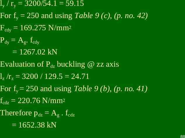
ly / ry 3200/54.1 59.15 For fy 250 and using Table 9 (c), (p. no. 42) Fcdy 169.275 N/mm2 Pdy Ag. fcdy 1267.02 kN Evaluation of Pdz buckling @ zz axis lz /rz 3200 / 129.5 24.71 For fy 250 and using Table 9 (b), (p. no. 41) fcdz 220.76 N/mm2 Therefore pdz Ag . fcdz 1652.38 kN 88
Kz 1 (λz – 0.2)nz Where, z fy f cr , z lz /rz 24.71, h/tf 300 / 10.6 28.30 From table 14 (p. no. 57) fcr,z 4040 N/mm2 Ratio of actual applied load to axial strength, nz 500 / 1625.38 0.30 ny 500 / 1267.02 0.39 λz 250/4040 0.246 89
Kz 1 (λz – 0.2) nz 1.0138 1 0.8 nz 1.24 . OK ψ ratio of minimum to maximum BM ψ -25 / 50 -1 / 2 Cmz 0.6 0.4 X (ψ) 0.4 K LT 1 0.1 LT n y CmLT 0.25 0.844 90
P Mz K LT 0.612 Pdy M dz 1 . OK P Cmz M z Kz 0.406 Pdz M dz 1 . OK Hence select ISHB 300 @ 0.58 kN/m as a section for eccentrically loaded column. 91
Design of Beam Column Working Stress Method IS : 800 - 1984 Checking section ISHB 300 @ 0.58 kN/m A 7485 sq mm σac,cal P/A 66.80 N/mm2 slenderness ratio L / ryy 59.15 for fy 250 Mpa, σac 121.15N/mm2 from table 5.1 (p. no. 39) 92
β ratio of smaller to larger moment 0.5 Therefore, Cmx 0.6 – 0.4 X 0.5 0.4 0.4 OK σbcx,cal. 50000 / 836.3 59.78 N/mm2 fcc elastic critical stress in compression π2E / λ2 563.6 N/mm2 σbcx Permissible bending stress in compression. As column is laterally unsupported following ratios are evaluated. D/T 28.30, L / ryy 59.15 As T / L 10.6 / 7.6 2 for fy 250 using table 6.1 B (p. no. 58) σbcx 150 N/mm2 93
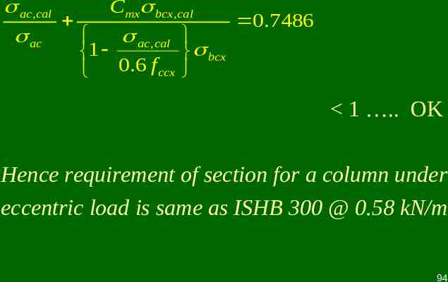
ac ,cal Cmx bcx ,cal 0.7486 ac ,cal ac 1 bcx 0.6 f ccx 1 . OK Hence requirement of section for a column under eccentric load is same as ISHB 300 @ 0.58 kN/m 94
Beam Column 1) 2) 3) 4) LSM Interaction betn axial & uniaxial bending is considered taking buckling due to axial loading about both axes of c/s Cmx 0.4 Combined interaction is considered for buckling @ both axes of cross section. Interaction values are @ yy axis 0.612 @ zz axis 0.406 1) 2) 3) 4) WSM Interaction is countered only by taking buckling due to axial load @ weaker axis with bending @ major axis. Cmx 0.4 Combined interaction is considered for buckling @ yy axis only. Interaction value is @ yy axis 0.7486 Thus reserve strength in a section by LSM is more than WSM. 95
THE END 96