Grounding and Bonding 101… Mark Kleine – N5HZR – BICSI trained


37 Slides3.81 MB
Grounding and Bonding 101 Mark Kleine – N5HZR – BICSI trained instructor [email protected]
Very Important You will learn 2 things today Grounded Electrode A conducting object through which a direct connection to earth is established. Bonding Jumper A reliable conductor to ensure the required electrical conductivity between metal parts required to be electrically connected.
Be very careful Mistakes in grounding and bonding can be life threatening. To you, or anyone near your electrical system. This information is provided to provide background information regarding this topic. If you’re unfamiliar with grounding systems, please seek professional assistance. Your mileage my vary. Add 6.95 for Postage and Handling. Please allow 6-8 weeks for delivery.
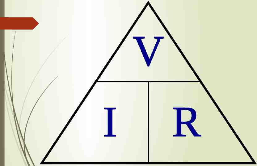
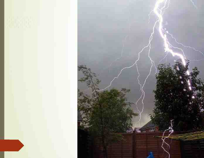
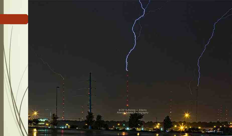
Why are we concerned about grounding? Grounding limits the voltage upon the circuit that might otherwise occur through exposure to lightning or other voltages higher than that for which the circuit is designed. Grounding limits the maximum voltage to ground under normal operating conditions. Grounding provides automatic opening procedure of the circuit if an accidental or fault ground occurs on one of its ungrounded conductors.
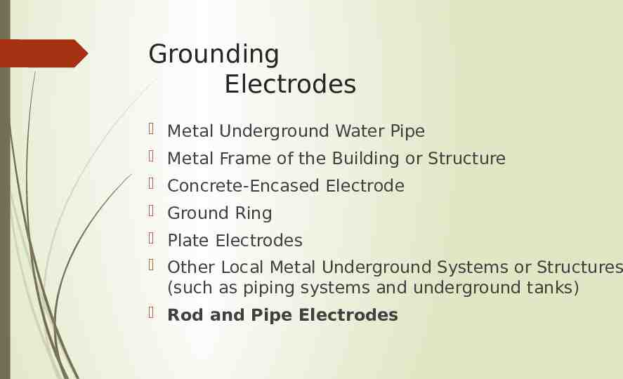
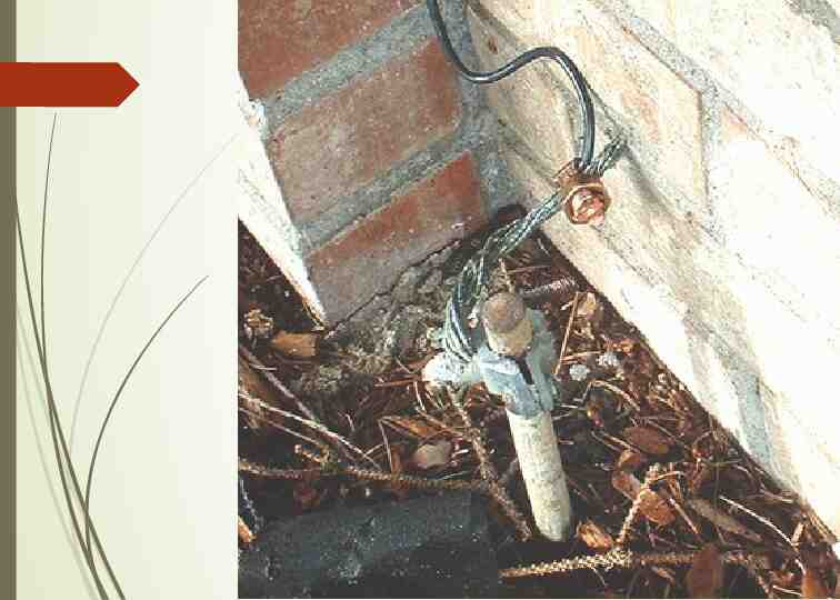
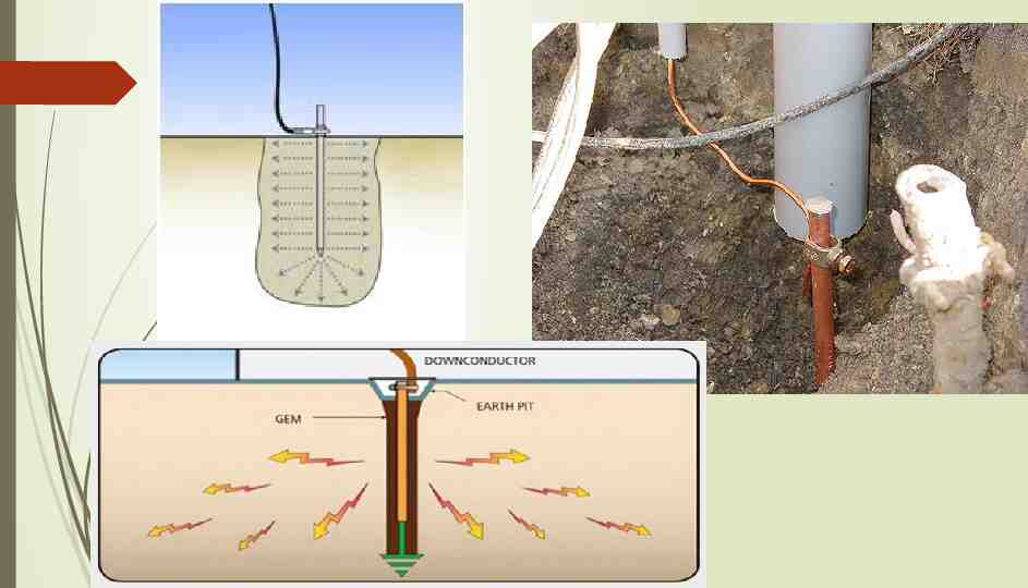
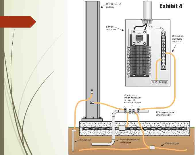
Grounding Electrodes Metal Underground Water Pipe Metal Frame of the Building or Structure Concrete-Encased Electrode Ground Ring Plate Electrodes Other Local Metal Underground Systems or Structures (such as piping systems and underground tanks) Rod and Pipe Electrodes
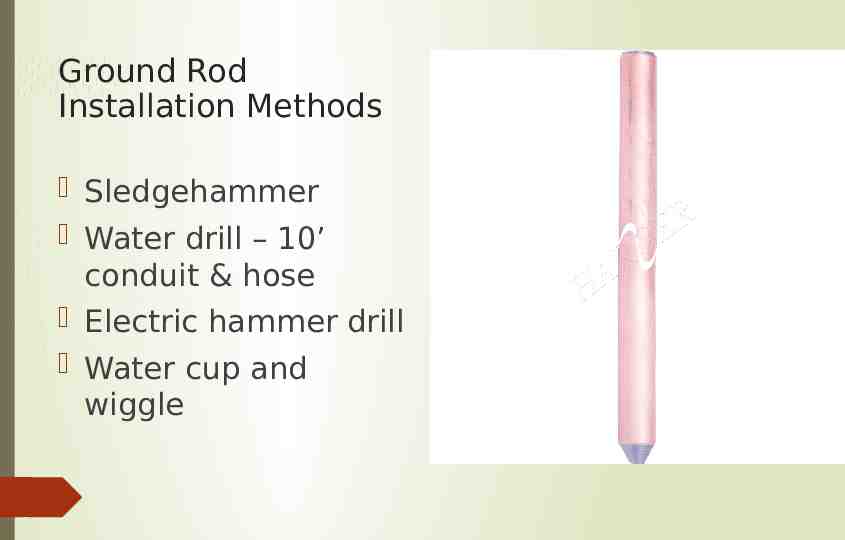
Ground Rod Installation Methods Sledgehammer Water drill – 10’ conduit & hose Electric hammer drill Water cup and wiggle
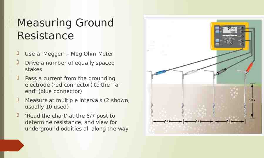
Measuring Ground Resistance Use a ‘Megger’ – Meg Ohm Meter Drive a number of equally spaced stakes Pass a current from the grounding electrode (red connector) to the ‘far end’ (blue connector) Measure at multiple intervals (2 shown, usually 10 used) ‘Read the chart’ at the 6/7 post to determine resistance, and view for underground oddities all along the way
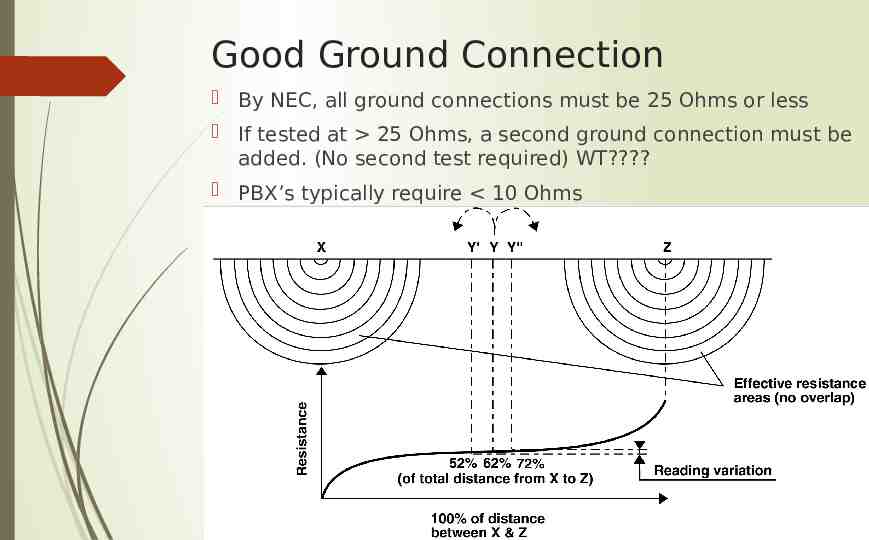
Good Ground Connection By NEC, all ground connections must be 25 Ohms or less If tested at 25 Ohms, a second ground connection must be added. (No second test required) WT? PBX’s typically require 10 Ohms
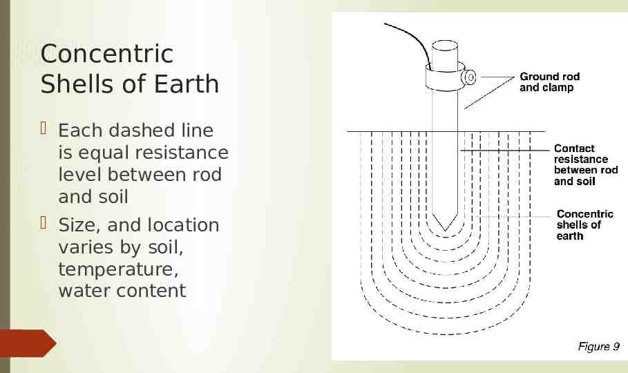
Concentric Shells of Earth Each dashed line is equal resistance level between rod and soil Size, and location varies by soil, temperature, water content
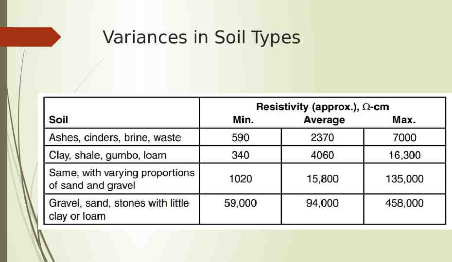
Variances in Soil Types
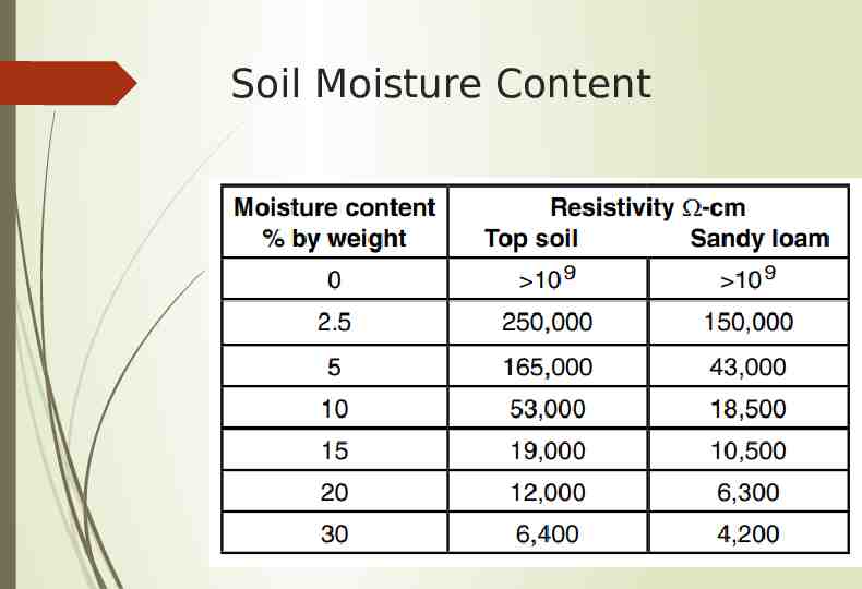
Soil Moisture Content
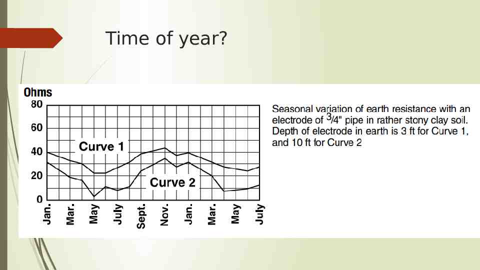
Time of year?
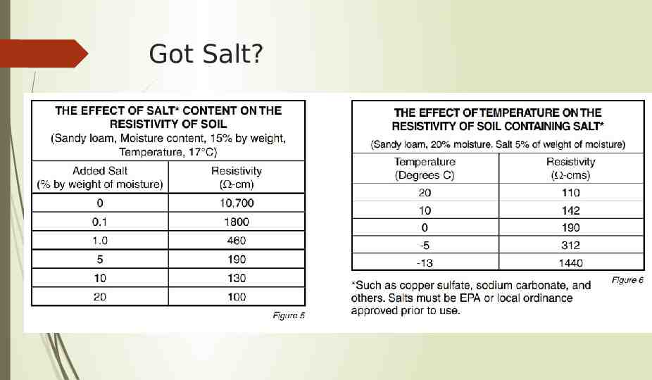
Got Salt?
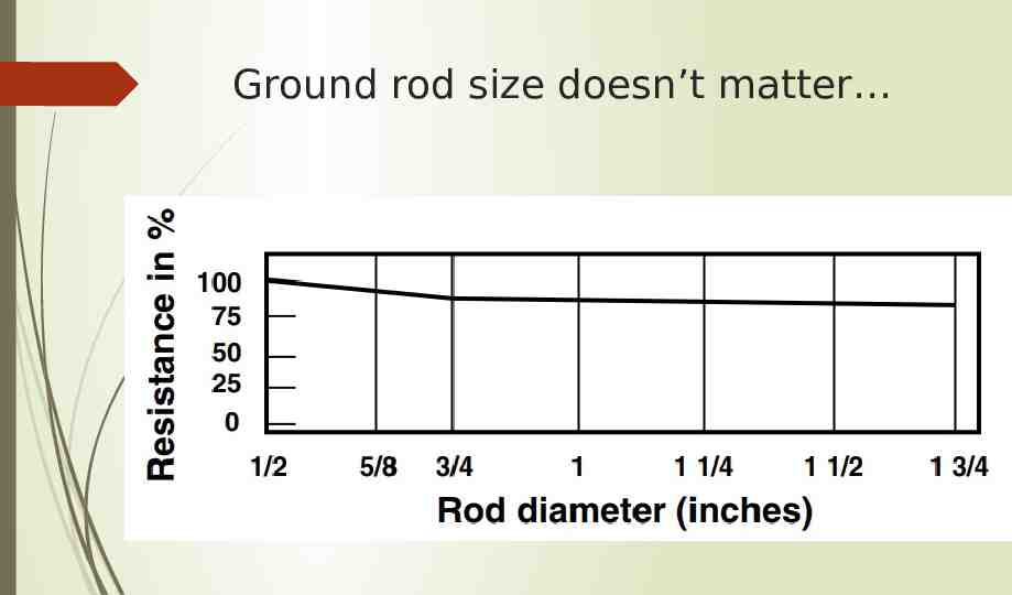
Ground rod size doesn’t matter
Bonding Conductors By code – 12/10/6 AWG Minimum Sized to carry maximum load Green insulation, or ‘Marked as green’ Clean connection Underground connections must be irreversible (crimping, or exothermic) Annual inspection to inspect and tighten entire grounding system
Inside your Electric Circuit breaker box
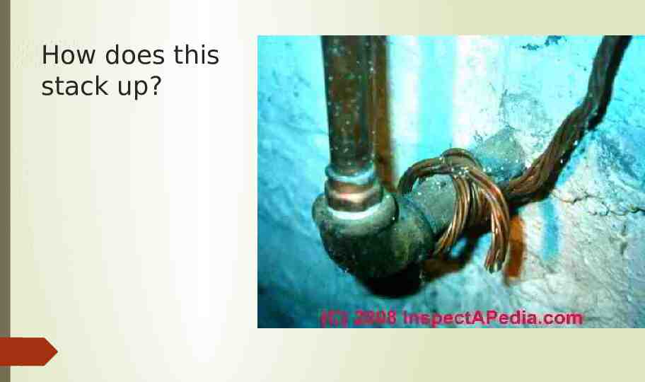
How does this stack up?
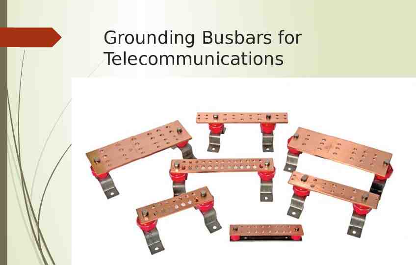
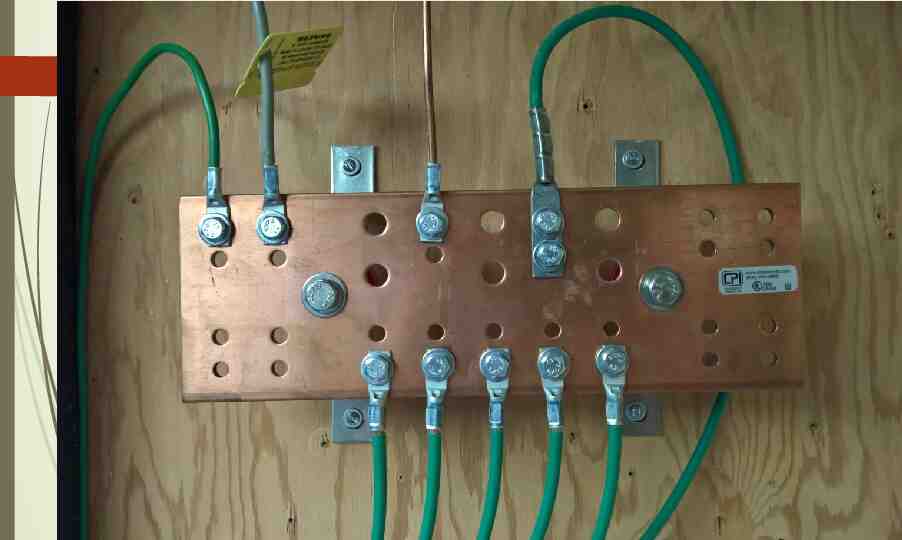
Grounding Busbars for Telecommunications
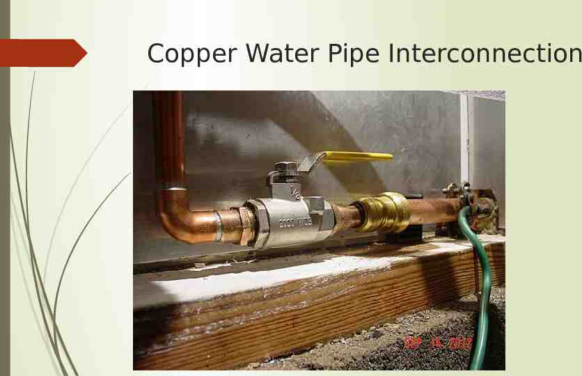
Copper Water Pipe Interconnection
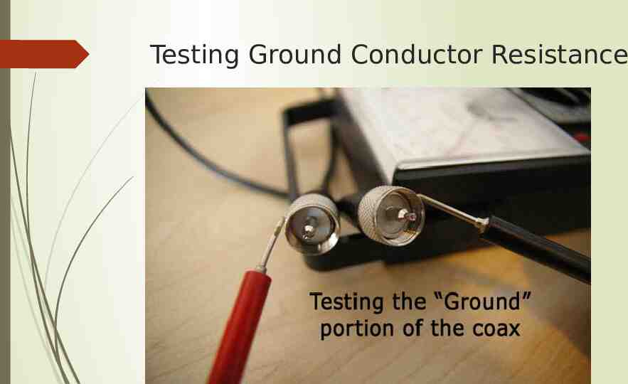
Testing Ground Conductor Resistance
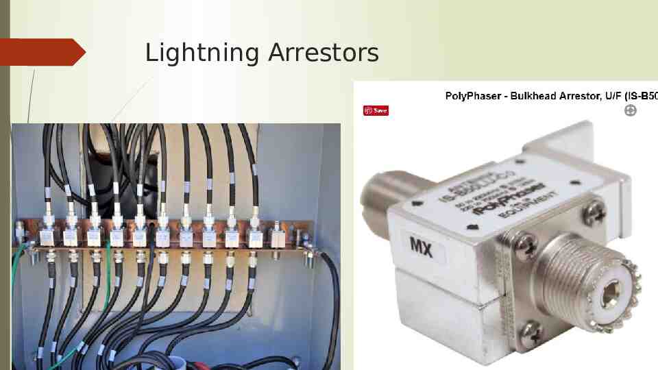
Lightning Arrestors
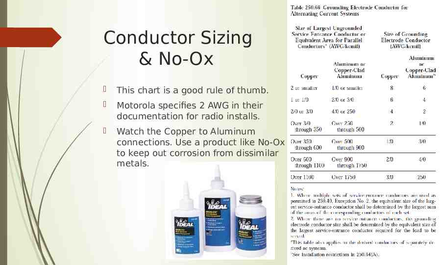
Conductor Sizing & No-Ox This chart is a good rule of thumb. Motorola specifies 2 AWG in their documentation for radio installs. Watch the Copper to Aluminum connections. Use a product like No-Ox to keep out corrosion from dissimilar metals.
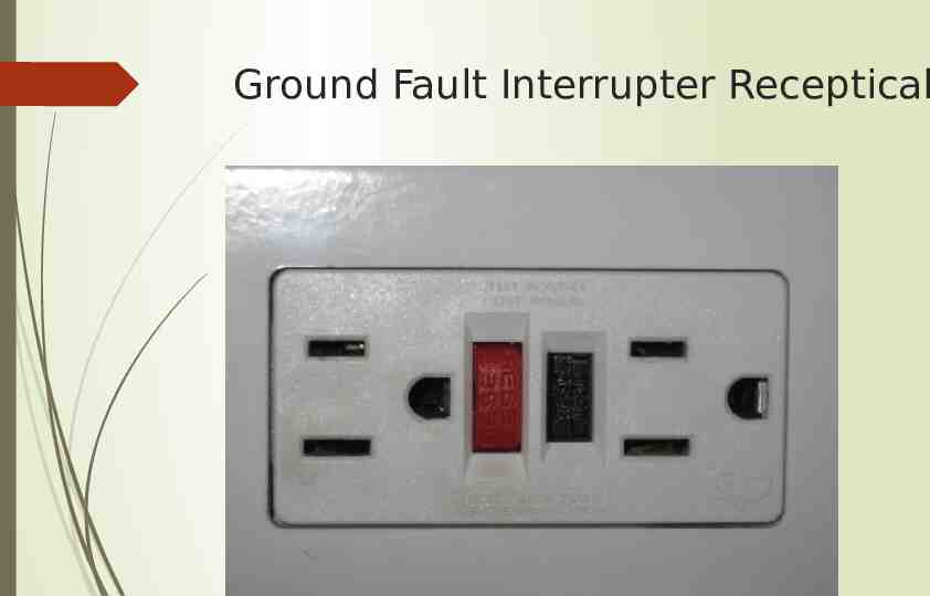
Ground Fault Interrupter Receptical
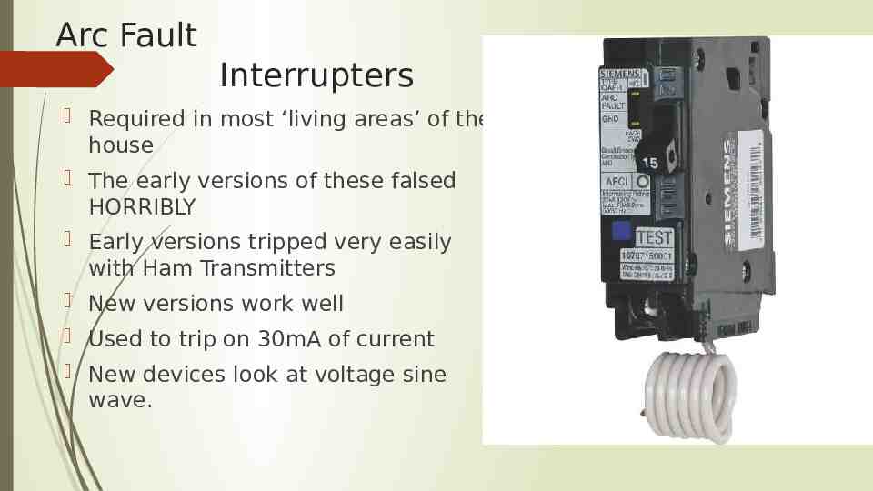
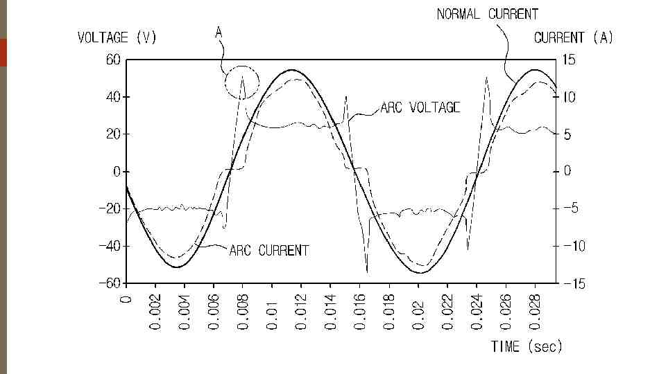
Arc Fault Interrupters Required in most ‘living areas’ of the house The early versions of these falsed HORRIBLY Early versions tripped very easily with Ham Transmitters New versions work well Used to trip on 30mA of current New devices look at voltage sine wave.
What Two Things Did you Learn Today?
For More Info National Electric Code NFP-70 NEC Article 250 – Grounding Requirements BISCI 607B – Telecommunications Harger – http://www.harger.com DxEngineering – http://www.dxengineering.com This Presentation, the Motorola Guide, and the Polyphaser document are located at http://w5nor.org/events (at the bottom, in the 2018 – February segment