Introduction to Electricity


48 Slides3.19 MB
Introduction to Electricity
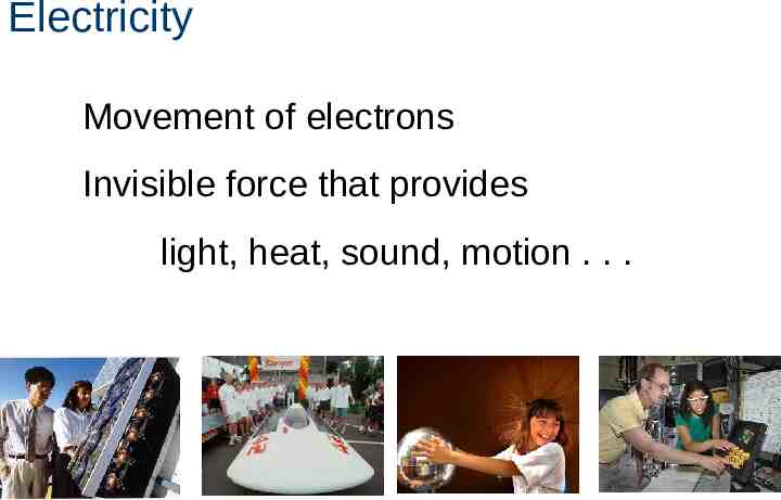
Electricity Movement of electrons Invisible force that provides light, heat, sound, motion . . .
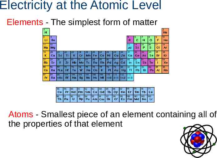
Electricity at the Atomic Level Elements - The simplest form of matter Atoms - Smallest piece of an element containing all of the properties of that element
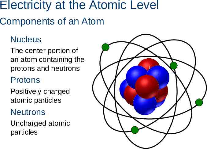
Electricity at the Atomic Level Components of an Atom Nucleus The center portion of an atom containing the protons and neutrons Protons Positively charged atomic particles Neutrons Uncharged atomic particles
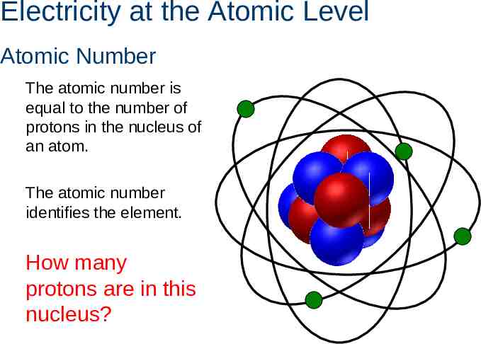
Electricity at the Atomic Level Atomic Number The atomic number is equal to the number of protons in the nucleus of an atom. The atomic number identifies the element. How many protons are in this nucleus?
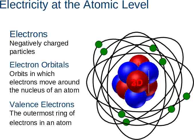
Electricity at the Atomic Level Electrons Negatively charged particles Electron Orbitals Orbits in which electrons move around the nucleus of an atom Valence Electrons The outermost ring of electrons in an atom 2D 3D
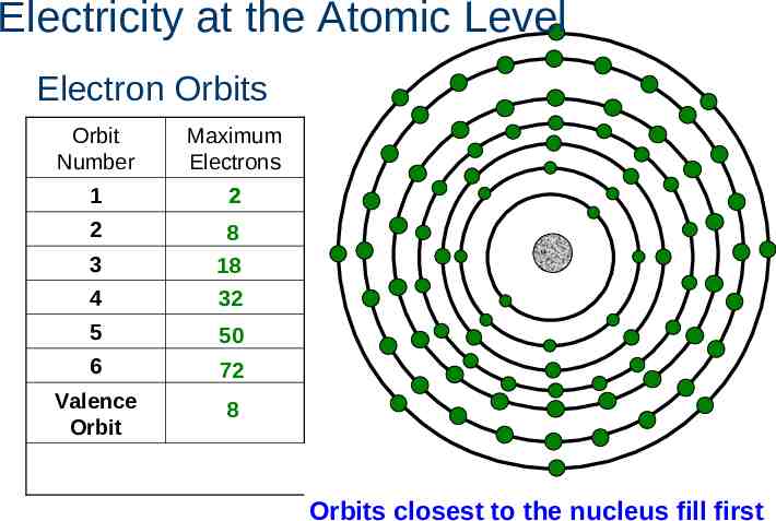
Electricity at the Atomic Level Electron Orbits Orbit Number Maximum Electrons 1 2 2 4 8 18 32 5 50 6 72 Valence Orbit 8 3 Orbits closest to the nucleus fill first
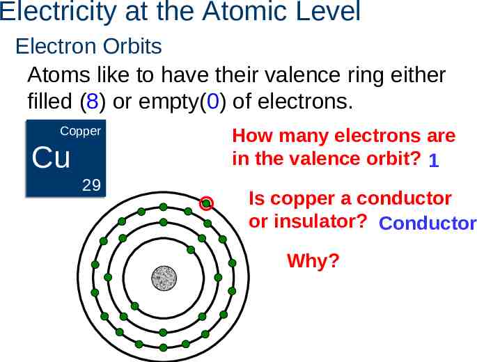
Electricity at the Atomic Level Electron Orbits Atoms like to have their valence ring either filled (8) or empty(0) of electrons. Copper Copper Cu 29 How many electrons are in the valence orbit? 1 Is copper a conductor or insulator? Conductor Why?
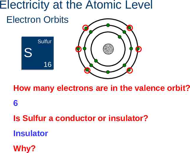
Electricity at the Atomic Level Electron Orbits Sulfur Sulfur S 16 How many electrons are in the valence orbit? 6 Is Sulfur a conductor or insulator? Insulator Why?
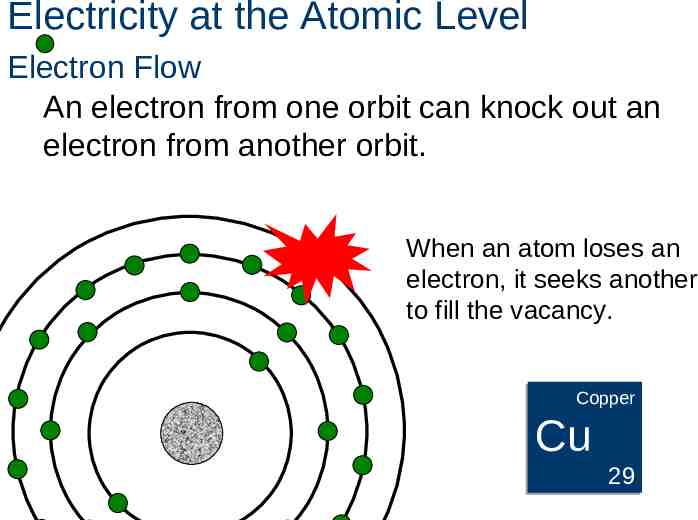
Electricity at the Atomic Level Electron Flow An electron from one orbit can knock out an electron from another orbit. When an atom loses an electron, it seeks another to fill the vacancy. Copper Copper Cu 29
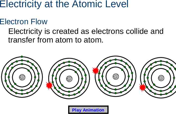
Electricity at the Atomic Level Electron Flow Electricity is created as electrons collide and transfer from atom to atom. Play Animation
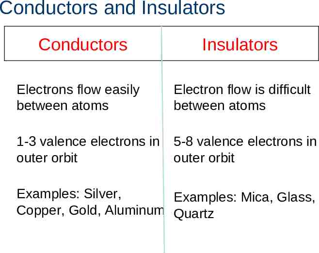
Conductors and Insulators Conductors Insulators Electrons flow easily between atoms Electron flow is difficult between atoms 1-3 valence electrons in outer orbit 5-8 valence electrons in outer orbit Examples: Silver, Examples: Mica, Glass, Copper, Gold, Aluminum Quartz
Conductors and Insulators Identify conductors and insulators Conductors Insulators
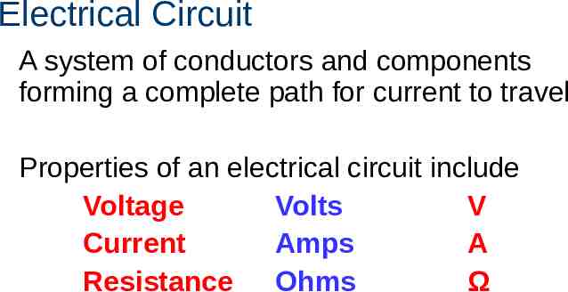
Electrical Circuit A system of conductors and components forming a complete path for current to travel Properties of an electrical circuit include Voltage Volts V Current Amps A Resistance Ohms Ω
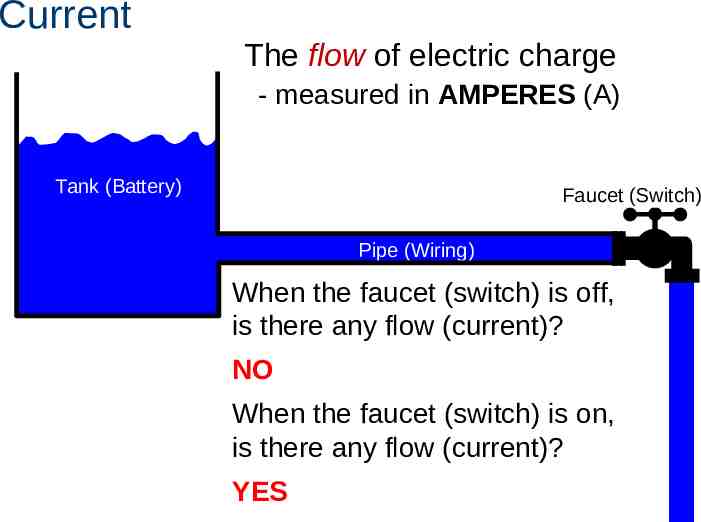
Current The flow of electric charge - measured in AMPERES (A) Tank (Battery) Faucet (Switch) Pipe (Wiring) When the faucet (switch) is off, is there any flow (current)? NO When the faucet (switch) is on, is there any flow (current)? YES
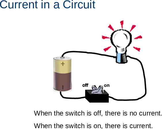
Current in a Circuit off on When the switch is off, there is no current. When the switch is on, there is current.
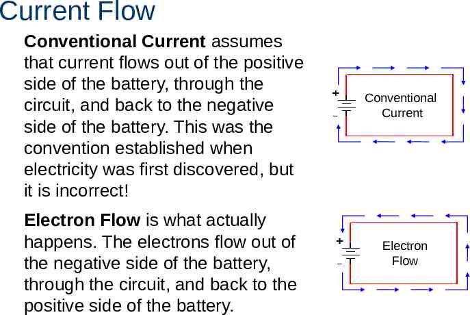
Current Flow Conventional Current assumes that current flows out of the positive side of the battery, through the circuit, and back to the negative side of the battery. This was the convention established when electricity was first discovered, but it is incorrect! Electron Flow is what actually happens. The electrons flow out of the negative side of the battery, through the circuit, and back to the positive side of the battery. Conventional Current Electron Flow
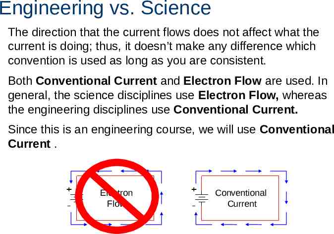
Engineering vs. Science The direction that the current flows does not affect what the current is doing; thus, it doesn’t make any difference which convention is used as long as you are consistent. Both Conventional Current and Electron Flow are used. In general, the science disciplines use Electron Flow, whereas the engineering disciplines use Conventional Current. Since this is an engineering course, we will use Conventional Current . Electron Flow Conventional Current
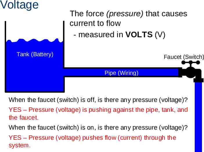
Voltage The force (pressure) that causes current to flow - measured in VOLTS (V) Tank (Battery) Faucet (Switch) Pipe (Wiring) When the faucet (switch) is off, is there any pressure (voltage)? YES – Pressure (voltage) is pushing against the pipe, tank, and the faucet. When the faucet (switch) is on, is there any pressure (voltage)? YES – Pressure (voltage) pushes flow (current) through the system.
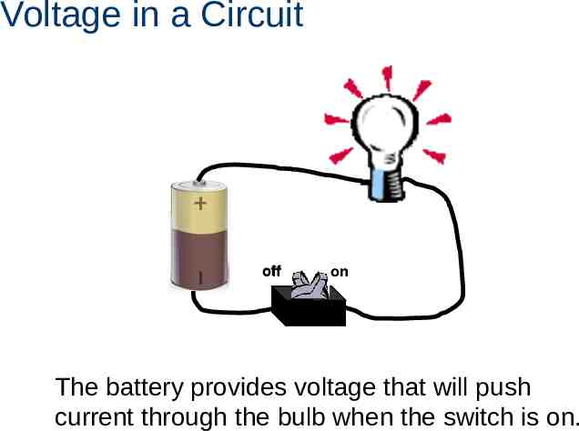
Voltage in a Circuit off on The battery provides voltage that will push current through the bulb when the switch is on.
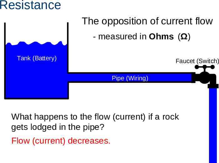
Resistance The opposition of current flow - measured in Ohms (Ω) Tank (Battery) Faucet (Switch) Pipe (Wiring) What happens to the flow (current) if a rock gets lodged in the pipe? Flow (current) decreases.
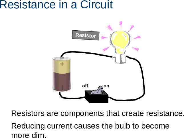
Resistance in a Circuit Resistor off on Resistors are components that create resistance. Reducing current causes the bulb to become more dim.
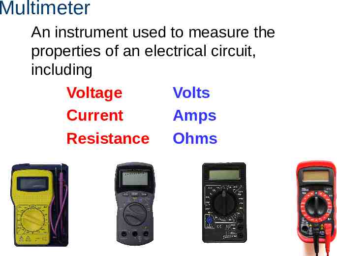
Multimeter An instrument used to measure the properties of an electrical circuit, including Voltage Volts Current Amps Resistance Ohms
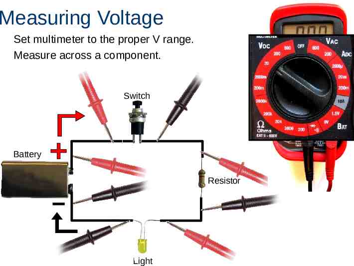
Measuring Voltage Set multimeter to the proper V range. Measure across a component. Switch Battery Resistor Light
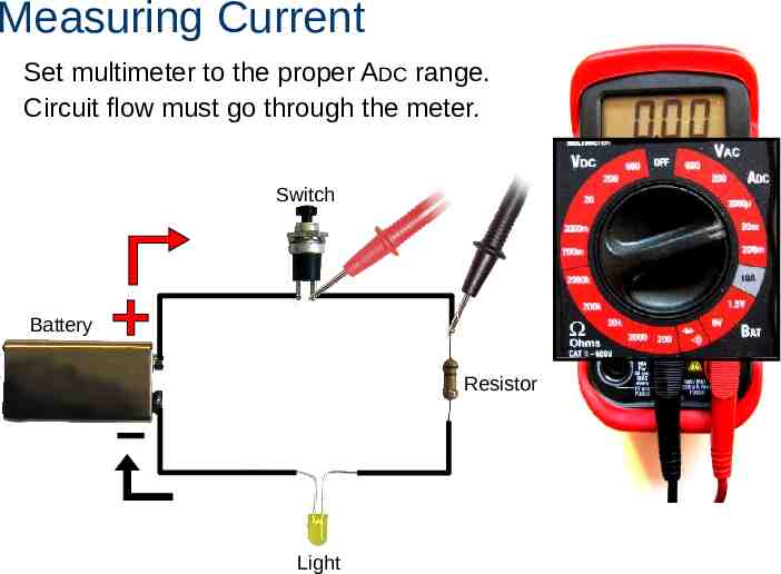
Measuring Current Set multimeter to the proper ADC range. Circuit flow must go through the meter. Switch Battery Resistor Light
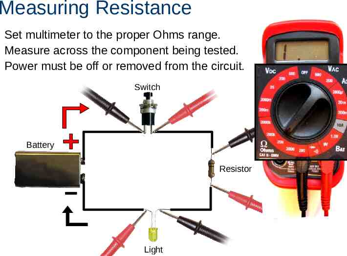
Measuring Resistance Set multimeter to the proper Ohms range. Measure across the component being tested. Power must be off or removed from the circuit. Switch Battery Resistor Light
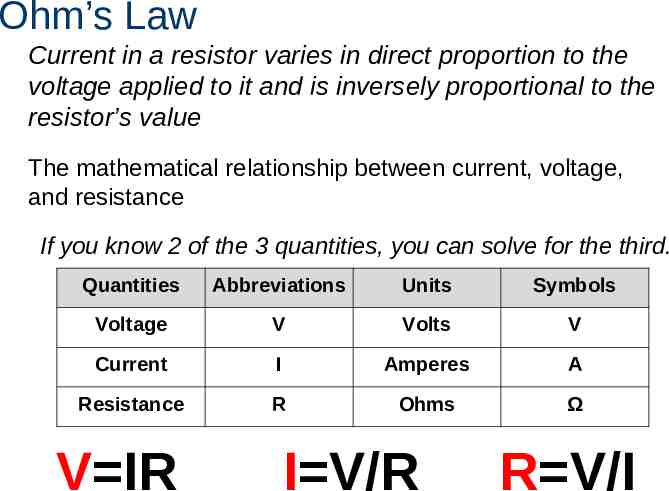
Ohm’s Law Current in a resistor varies in direct proportion to the voltage applied to it and is inversely proportional to the resistor’s value The mathematical relationship between current, voltage, and resistance If you know 2 of the 3 quantities, you can solve for the third. Quantities Abbreviations Units Symbols Voltage V Volts V Current I Amperes A Resistance R Ohms Ω V IR I V/R R V/I
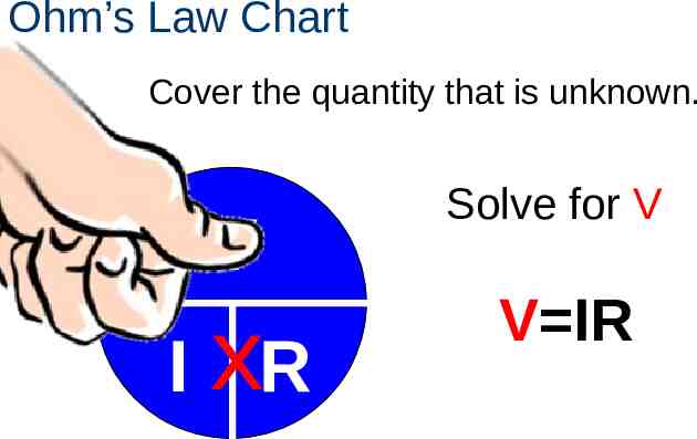
Ohm’s Law Chart Cover the quantity that is unknown. V I xR Solve for V V IR
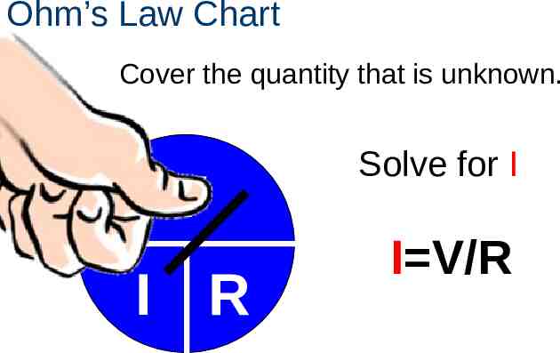
Ohm’s Law Chart Cover the quantity that is unknown. V I R Solve for I I V/R
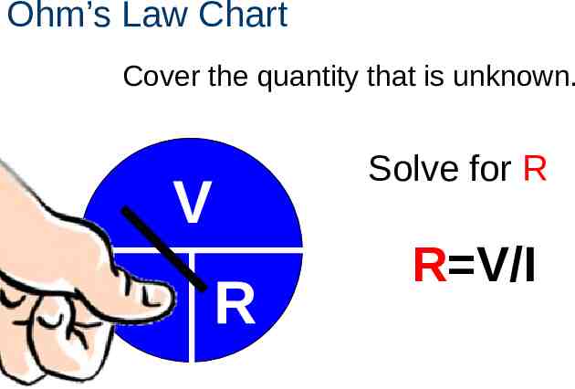
Ohm’s Law Chart Cover the quantity that is unknown. V I R Solve for R R V/I
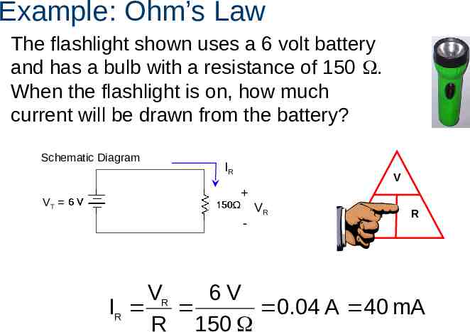
Example: Ohm’s Law The flashlight shown uses a 6 volt battery and has a bulb with a resistance of 150 . When the flashlight is on, how much current will be drawn from the battery? Schematic Diagram VT IR V - VR I R VR 6V IR 0.04 A 40 mA R 150
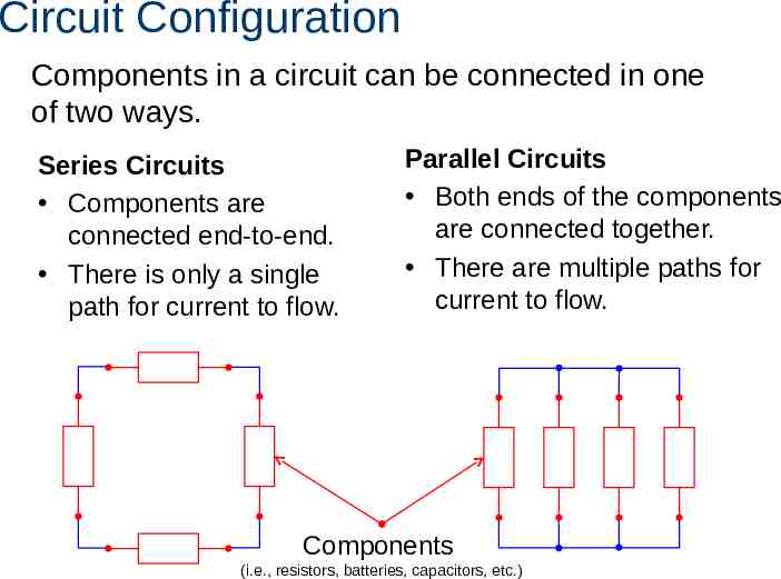
Circuit Configuration Components in a circuit can be connected in one of two ways. Series Circuits Components are connected end-to-end. There is only a single path for current to flow. Parallel Circuits Both ends of the components are connected together. There are multiple paths for current to flow. Components (i.e., resistors, batteries, capacitors, etc.)
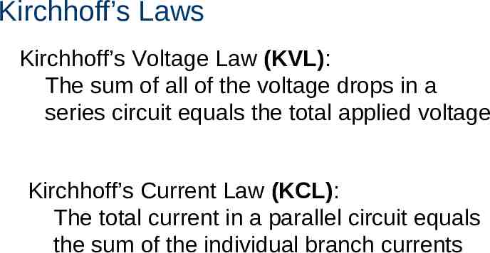
Kirchhoff’s Laws Kirchhoff’s Voltage Law (KVL): The sum of all of the voltage drops in a series circuit equals the total applied voltage Kirchhoff’s Current Law (KCL): The total current in a parallel circuit equals the sum of the individual branch currents
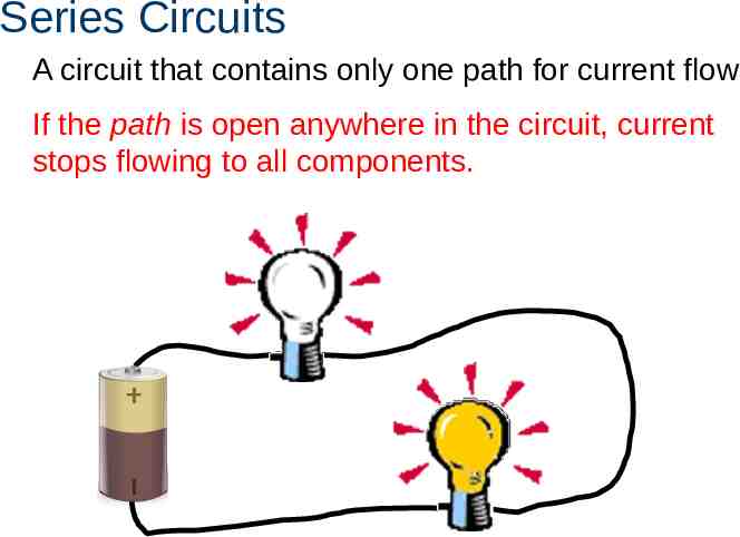
Series Circuits A circuit that contains only one path for current flow If the path is open anywhere in the circuit, current stops flowing to all components.
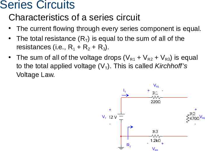
Series Circuits Characteristics of a series circuit The current flowing through every series component is equal. The total resistance (RT) is equal to the sum of all of the resistances (i.e., R1 R2 R3). The sum of all of the voltage drops (V R1 VR2 VR3) is equal to the total applied voltage (VT). This is called Kirchhoff’s Voltage Law. VR1 IT - VR2 VT - - RT - VR3
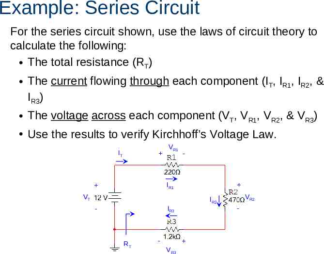
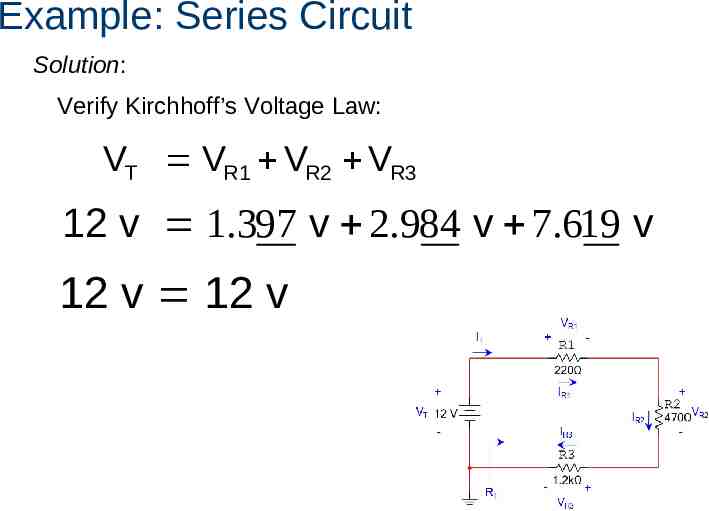
Example: Series Circuit For the series circuit shown, use the laws of circuit theory to calculate the following: The total resistance (RT) The current flowing through each component (IT, IR1, IR2, & IR3) The voltage across each component (VT, VR1, VR2, & VR3) Use the results to verify Kirchhoff’s Voltage Law. IT VR1 - IR1 VT VR2 IR2 - - IR3 RT - VR3
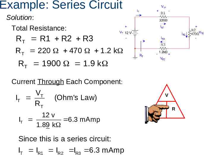
Example: Series Circuit Solution: Total Resistance: RT R1 R2 R3 RT 220 470 1.2 k RT 1900 1.9 k Current Through Each Component: IT IT VT RT V (Ohm's Law) 12 v 6.3 mAmp 1.89 k Since this is a series circuit: IT IR1 IR2 IR3 6.3 mAmp I R
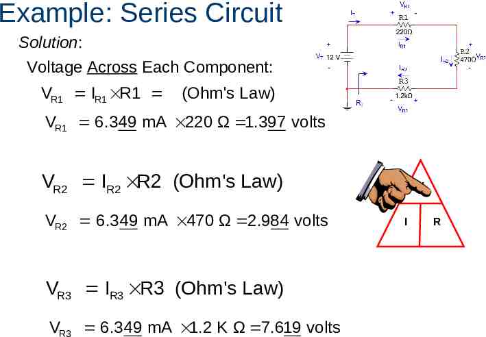
Example: Series Circuit Solution: Voltage Across Each Component: VR1 IR1 R1 (Ohm's Law) VR1 6.349 mA 220 Ω 1.397 volts VR2 IR2 R2 (Ohm's Law) VR2 6.349 mA 470 Ω 2.984 volts VR3 IR3 R3 (Ohm's Law) VR3 6.349 mA 1.2 K Ω 7.619 volts V I R
Example: Series Circuit Solution: Verify Kirchhoff’s Voltage Law: VT VR1 VR2 VR3 12 v 1.397 v 2.984 v 7.619 v 12 v 12 v
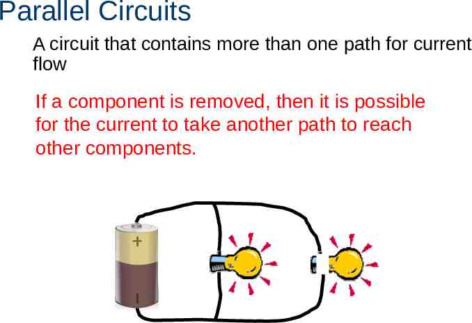
Parallel Circuits A circuit that contains more than one path for current flow If a component is removed, then it is possible for the current to take another path to reach other components.
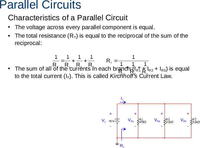
Parallel Circuits Characteristics of a Parallel Circuit The voltage across every parallel component is equal. The total resistance (RT) is equal to the reciprocal of the sum of the reciprocal: 1 1 1 1 R T R1 R 2 R 3 1 1 1 1 The sum of all of the currents in each branch R1 R(I2 R1 R 3IR2 IR3) is equal RT to the total current (IT). This is called Kirchhoff’s Current Law. IT VR1 VT VR2 - - RT VR3 - -
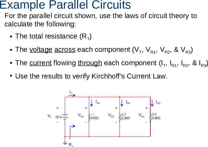
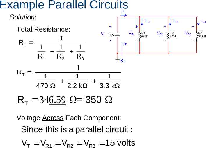
Example Parallel Circuits For the parallel circuit shown, use the laws of circuit theory to calculate the following: The total resistance (RT) The voltage across each component (VT, VR1, VR2, & VR3) The current flowing through each component (IT, IR1, IR2, & IR3) Use the results to verify Kirchhoff’s Current Law. IT IR1 IR2 VR1 VT VR2 - - IR3 VR3 - - 42 RT
Example Parallel Circuits Solution: Total Resistance: 1 RT 1 1 1 R1 R2 R3 1 RT 1 1 1 470 2.2 k 3.3 k RT 346.59 350 Voltage Across Each Component: Since this is a parallel circuit : VT VR1 VR2 VR3 15 volts
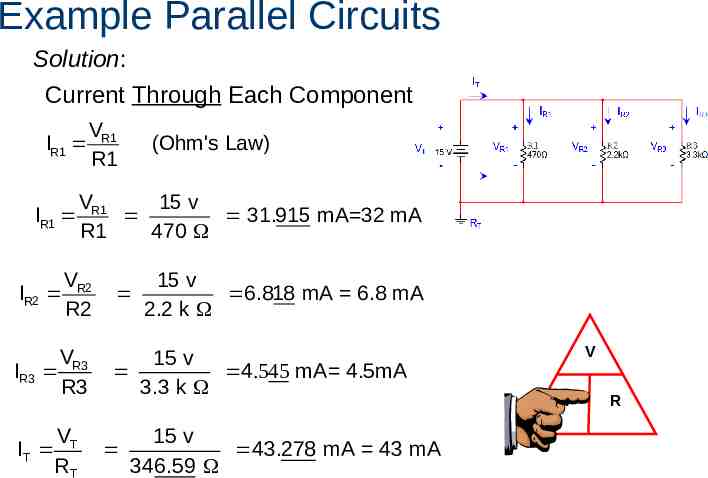
Example Parallel Circuits Solution: Current Through Each Component: IR1 IR1 VR1 R1 (Ohm's Law) VR1 15 v 31.915 mA 32 mA R1 470 IR2 VR2 R2 15 v 6.818 mA 6.8 mA 2.2 k IR3 V R3 R3 15 v 4.545 mA 4.5mA 3.3 k IT VT RT 15 v 43.278 mA 43 mA 346.59 V I R
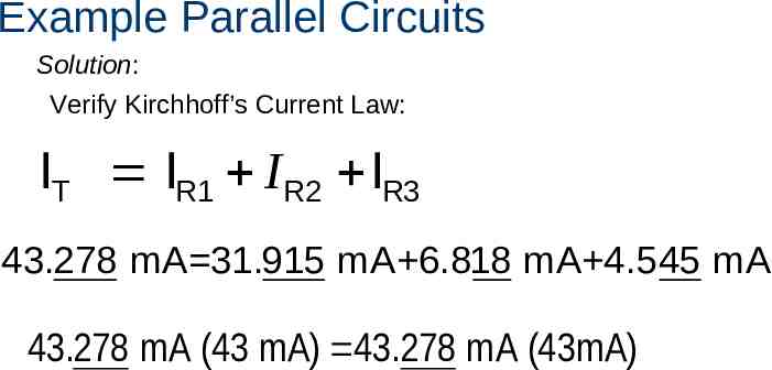
Example Parallel Circuits Solution: Verify Kirchhoff’s Current Law: IT IR1 IR2 IR3 43.278 mA 31.915 mA 6.818 mA 4.545 mA 43.278 mA (43 mA) 43.278 mA (43mA)
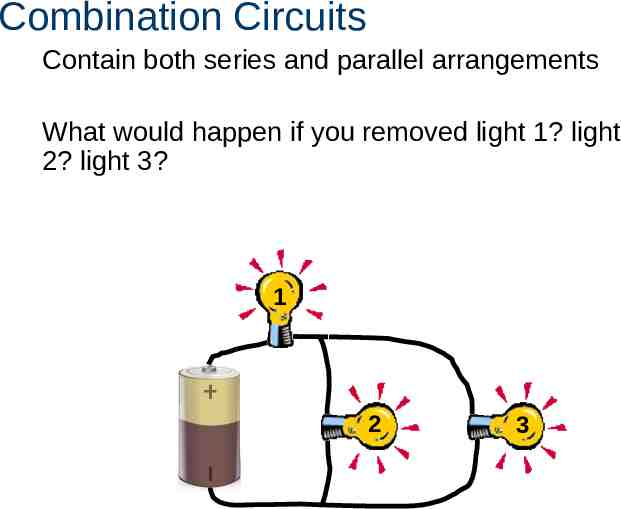
Combination Circuits Contain both series and parallel arrangements What would happen if you removed light 1? light 2? light 3? 1 2 3
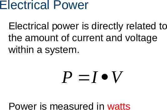
Electrical Power Electrical power is directly related to the amount of current and voltage within a system. P I V Power is measured in watts
Image Resources Microsoft, Inc. (2008). Clip Art. Retrieved November 20, 2008, from http://office.microsoft.com/en-us/clipart/default.aspx