MANUFACTURING TECHNOLOGY UNIT – III THEORY OF METAL CUTTING


79 Slides2.54 MB
MANUFACTURING TECHNOLOGY UNIT – III THEORY OF METAL CUTTING
Manufacturing Technology Broad classification of Engineering Manufacturing Processes. It is extremely difficult to tell the exact number of various manufacturing processes existing and are being practiced presently because very large number of processes have been developed till now and the number is still increasing exponentially with the growing demands and rapid progress in science and technology. However, all such manufacturing processes can be broadly classified in four major groups as follows Shaping or forming Manufacturing a solid product of definite size and shape from a given material taken in three possible states: in liquid or semi-liquid state – e.g., casting, injection moulding etc. in solid state – e.g., forging rolling, extrusion, drawing etc. in powder form – e.g., powder metallurgical process.
Manufacturing Technology Joining process Welding, brazing, soldering etc. Removal or Cutting process Machining (Traditional or Non-traditional), Grinding etc. Regenerative manufacturing Process Production of solid products in layer by layer from raw materials in different form: liquid – e.g., stereo lithography powder – e.g., selective sintering sheet – e.g., LOM (laminated object manufacturing) wire – e.g., FDM. (Fused Deposition Modeling) Out of the fore said groups, Regenerative Manufacturing is the latest one which is generally accomplished very rapidly and quite accurately using CAD and CAM for Rapid Prototyping and Tooling.
Manufacturing Technology Material Removal Processes – Metal Cutting Process A family of shaping operations, the common feature of which is removal of material from a starting work part so the remaining part has the desired geometry Traditional Process (Machining) – Material removal by a sharp cutting tool, e.g., turning, milling, drilling Nontraditional processes - Various energy forms other than sharp cutting tool to remove material. e.g., Laser and Electron Beam machining Abrasive processes – Material removal by hard, abrasive particles, e.g., grinding
Manufacturing Technology Why Machining is Important Variety of work materials can be machined Most frequently used to cut metals Variety of part shapes and special geometric features possible, such as: Screw threads Accurate round holes Very straight edges and surfaces Good dimensional accuracy and surface finish
Manufacturing Technology Disadvantages with Machining Wasteful of material Chips generated in machining are wasted material, at least in the unit operation Time consuming A machining operation generally takes more time to shape a given part than alternative shaping processes, such as casting, powder metallurgy, or forming
Manufacturing Technology Machining in Manufacturing Sequence Generally performed after other manufacturing processes, such as casting, forging, and bar drawing Other processes create the general shape of the starting work part Machining provides the final shape, dimensions, finish, and special geometric details that other processes cannot create
Manufacturing Technology Machining Operations Most important machining operations Turning Drilling Milling Other machining operations Shaping and planing Broaching Sawing
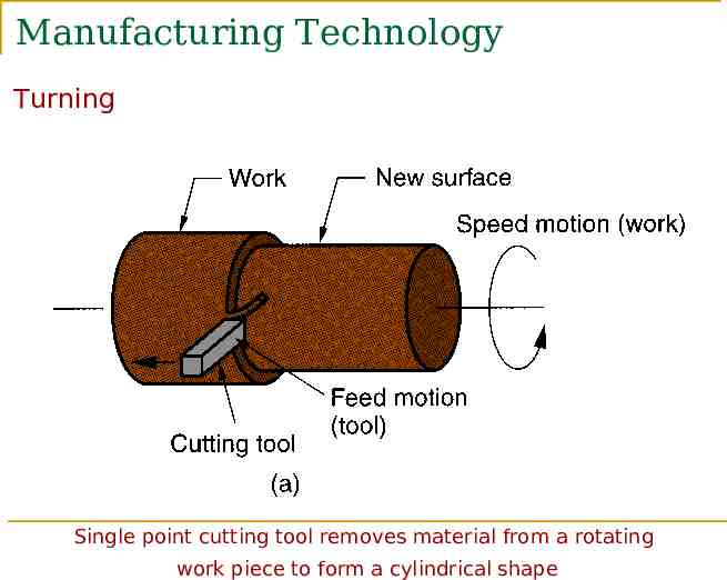
Manufacturing Technology Turning Single point cutting tool removes material from a rotating work piece to form a cylindrical shape
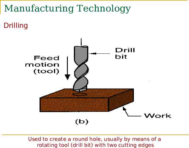
Manufacturing Technology Drilling Used to create a round hole, usually by means of a rotating tool (drill bit) with two cutting edges
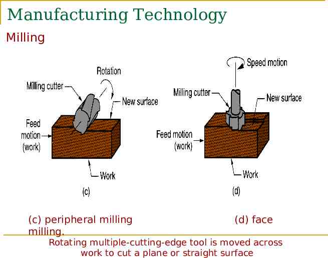
Manufacturing Technology Milling (c) peripheral milling milling. (d) face Rotating multiple-cutting-edge tool is moved across work to cut a plane or straight surface
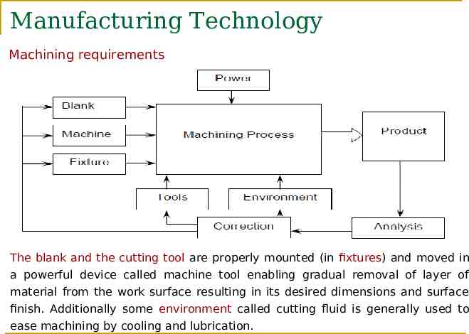
Manufacturing Technology Machining requirements The blank and the cutting tool are properly mounted (in fixtures) and moved in a powerful device called machine tool enabling gradual removal of layer of material from the work surface resulting in its desired dimensions and surface finish. Additionally some environment called cutting fluid is generally used to ease machining by cooling and lubrication.
Manufacturing Technology Machine Tool - Definition A machine tool is a non-portable power operated and reasonably valued device or system of devices in which energy is expended to produce jobs of desired size, shape and surface finish by removing excess material from the preformed blanks in the form of chips with the help of cutting tools moved past the work surface's. Basic functions of Machine Tools Machine Tools basically produce geometrical surfaces like flat, cylindrical or any contour on the preformed blanks by machining work with the help of cutting tools.
Manufacturing Technology The physical functions of a Machine Tool in machining are Firmly holding the blank and the tool Transmit motions to the tool and the blank Provide power to the tool-work pair for the machining action. Control of the machining parameters, (speed, feed and depth of cut).
Manufacturing Technology Classification of cutting tools Single-Point Cutting Edge Tools One dominant cutting edge Point is usually rounded to form a nose radius Turning uses single point tools Multiple Point Cutting Edge Tools More than one cutting edge Motion relative to work achieved by rotating Drilling and milling use rotating multiple cutting edge tools
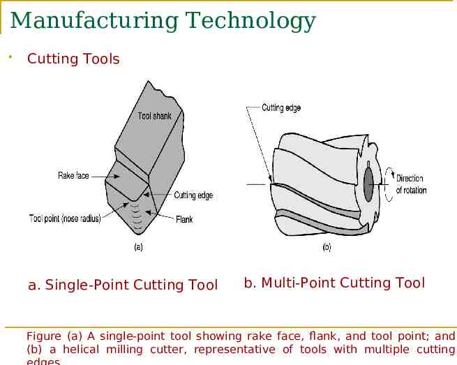
Manufacturing Technology Cutting Tools a. Single-Point Cutting Tool b. Multi-Point Cutting Tool Figure (a) A single‑point tool showing rake face, flank, and tool point; and (b) a helical milling cutter, representative of tools with multiple cutting
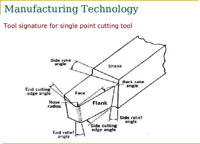
Manufacturing Technology Tool signature for single point cutting tool Flank
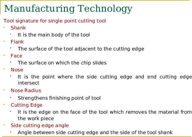
Manufacturing Technology Tool signature for single point cutting tool Shank It is the main body of the tool Flank The surface of the tool adjacent to the cutting edge Face The surface on which the chip slides Nose It is the point where the side cutting edge and end cutting edge intersect Nose Radius Strengthens finishing point of tool Cutting Edge It is the edge on the face of the tool which removes the material from the work piece Side cutting edge angle Angle between side cutting edge and the side of the tool shank
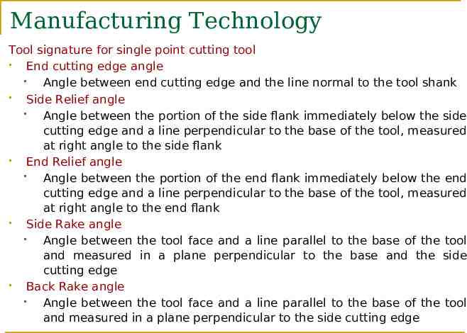
Manufacturing Technology Tool signature for single point cutting tool End cutting edge angle Angle between end cutting edge and the line normal to the tool shank Side Relief angle Angle between the portion of the side flank immediately below the side cutting edge and a line perpendicular to the base of the tool, measured at right angle to the side flank End Relief angle Angle between the portion of the end flank immediately below the end cutting edge and a line perpendicular to the base of the tool, measured at right angle to the end flank Side Rake angle Angle between the tool face and a line parallel to the base of the tool and measured in a plane perpendicular to the base and the side cutting edge Back Rake angle Angle between the tool face and a line parallel to the base of the tool and measured in a plane perpendicular to the side cutting edge
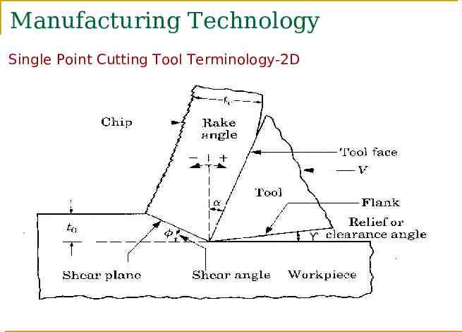
Manufacturing Technology Single Point Cutting Tool Terminology-2D Ƴ
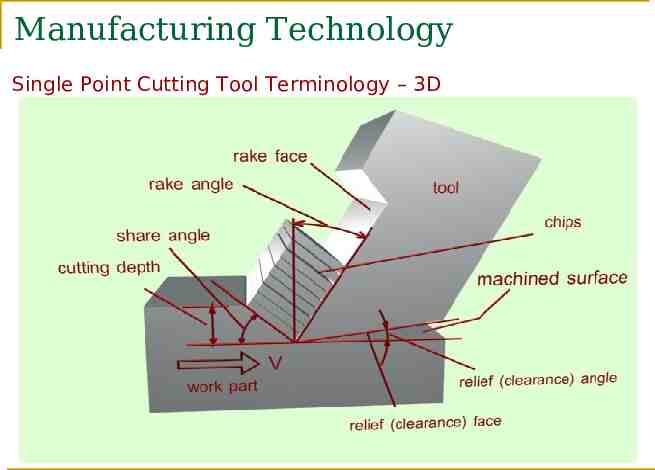
Manufacturing Technology Single Point Cutting Tool Terminology – 3D
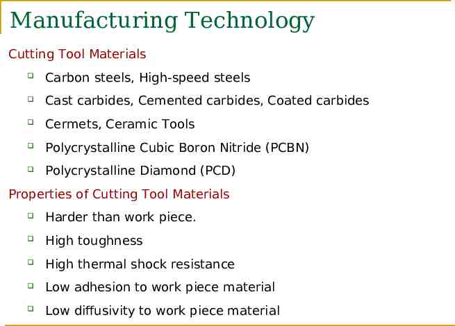
Manufacturing Technology Cutting Tool Materials Carbon steels, High-speed steels Cast carbides, Cemented carbides, Coated carbides Cermets, Ceramic Tools Polycrystalline Cubic Boron Nitride (PCBN) Polycrystalline Diamond (PCD) Properties of Cutting Tool Materials Harder than work piece. High toughness High thermal shock resistance Low adhesion to work piece material Low diffusivity to work piece material
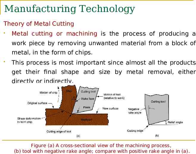
Manufacturing Technology Theory of Metal Cutting Metal cutting or machining is the process of producing a work piece by removing unwanted material from a block of metal, in the form of chips. This process is most important since almost all the products get their final shape and size by metal removal, either directly or indirectly. Figure (a) A cross‑sectional view of the machining process, (b) tool with negative rake angle; compare with positive rake angle in (a).
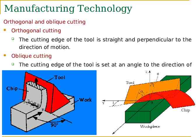
Manufacturing Technology Orthogonal and oblique cutting Orthogonal cutting The cutting edge of the tool is straight and perpendicular to the direction of motion. Oblique cutting The cutting edge of the tool is set at an angle to the direction of motion.
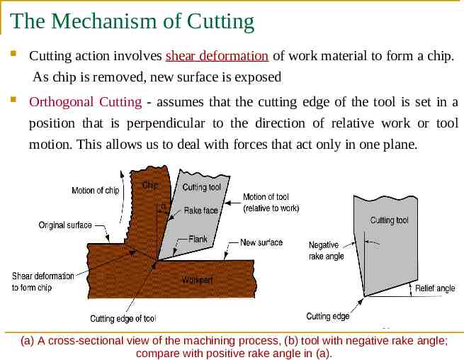
The Mechanism of Cutting Cutting action involves shear deformation of work material to form a chip. As chip is removed, new surface is exposed Orthogonal Cutting - assumes that the cutting edge of the tool is set in a position that is perpendicular to the direction of relative work or tool motion. This allows us to deal with forces that act only in one plane. (a) A cross‑sectional view of the machining process, (b) tool with negative rake angle; compare with positive rake angle in (a).
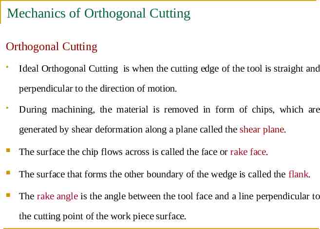
Mechanics of Orthogonal Cutting Orthogonal Cutting Ideal Orthogonal Cutting is when the cutting edge of the tool is straight and perpendicular to the direction of motion. During machining, the material is removed in form of chips, which are generated by shear deformation along a plane called the shear plane. The surface the chip flows across is called the face or rake face. The surface that forms the other boundary of the wedge is called the flank. The rake angle is the angle between the tool face and a line perpendicular to the cutting point of the work piece surface.
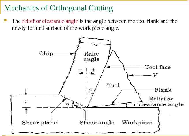
Mechanics of Orthogonal Cutting The relief or clearance angle is the angle between the tool flank and the newly formed surface of the work piece angle.
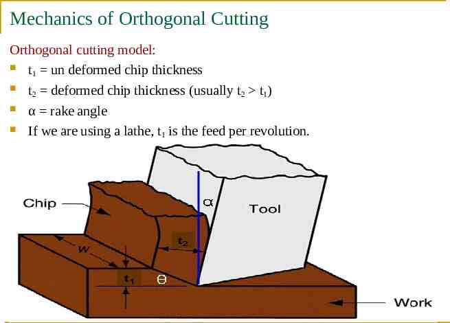
Mechanics of Orthogonal Cutting Orthogonal cutting model: t un deformed chip thickness 1 t2 deformed chip thickness (usually t2 t1) α rake angle If we are using a lathe, t1 is the feed per revolution.
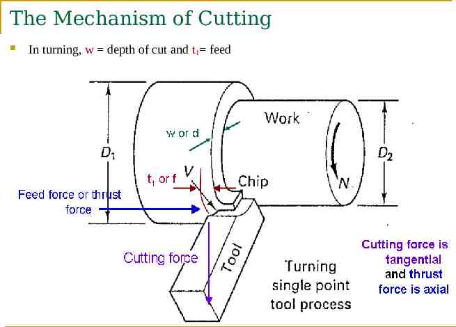
The Mechanism of Cutting In turning, w depth of cut and t1 feed
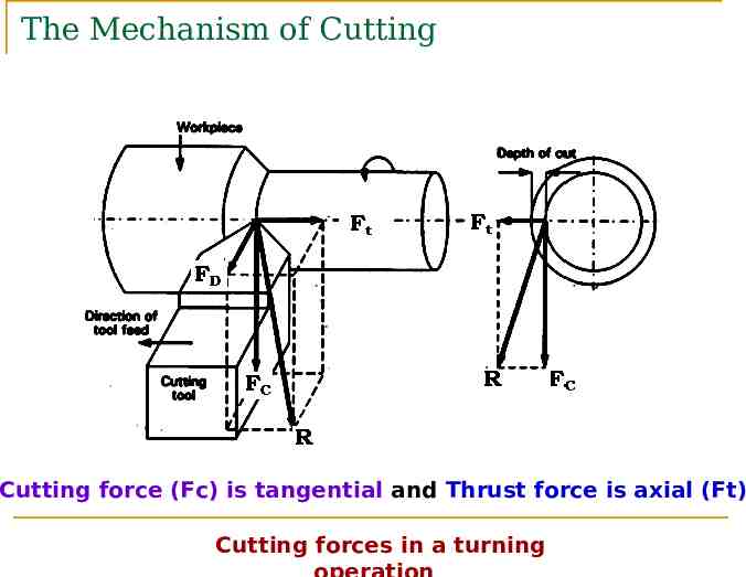
The Mechanism of Cutting Cutting force (Fc) is tangential and Thrust force is axial (Ft) Cutting forces in a turning
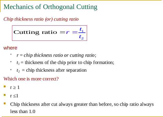
Mechanics of Orthogonal Cutting Chip thickness ratio (or) cutting ratio Cutting ratio r t1 t2 where r chip thickness ratio or cutting ratio; t1 thickness of the chip prior to chip formation; t2 chip thickness after separation Which one is more correct? r 1 r 1 Chip thickness after cut always greater than before, so chip ratio always less than 1.0
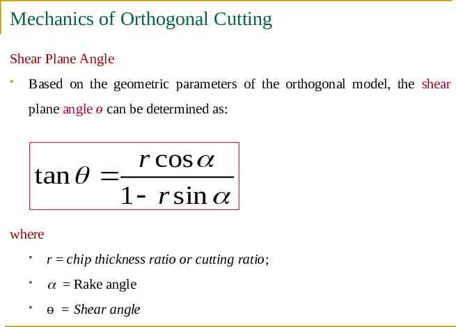
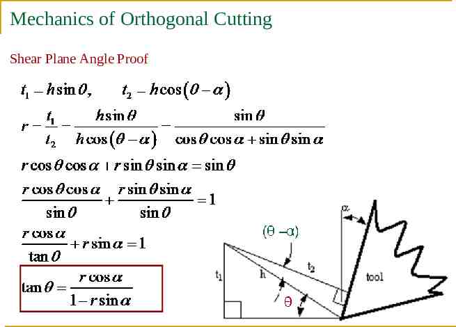
Mechanics of Orthogonal Cutting Shear Plane Angle Based on the geometric parameters of the orthogonal model, the shear plane angle ө can be determined as: r cos tan 1 r sin where r chip thickness ratio or cutting ratio; Rake angle ө Shear angle
Mechanics of Orthogonal Cutting Shear Plane Angle Proof
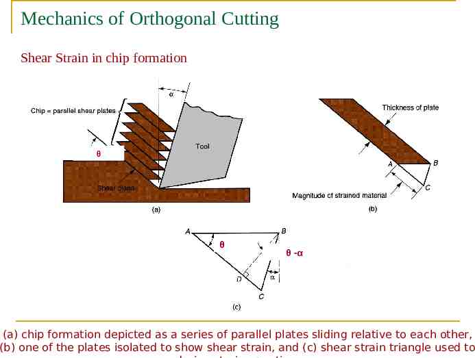
Mechanics of Orthogonal Cutting Shear Strain in chip formation θ θ θ -α (a) chip formation depicted as a series of parallel plates sliding relative to each other, (b) one of the plates isolated to show shear strain, and (c) shear strain triangle used to
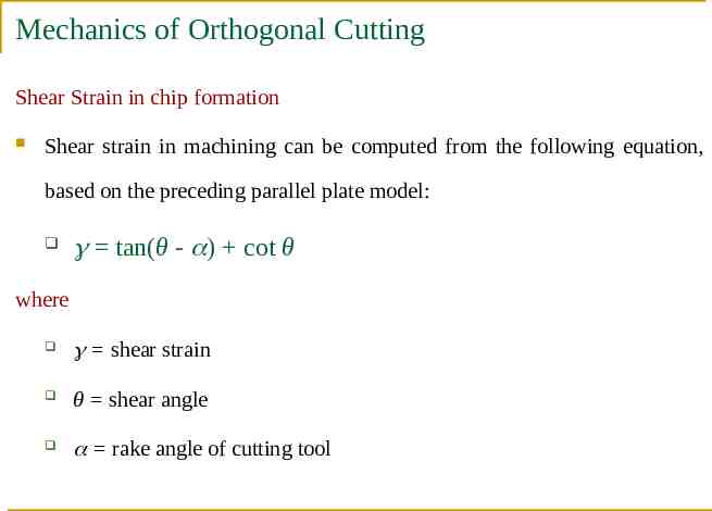
Mechanics of Orthogonal Cutting Shear Strain in chip formation Shear strain in machining can be computed from the following equation, based on the preceding parallel plate model: tan(θ - ) cot θ where shear strain θ shear angle rake angle of cutting tool
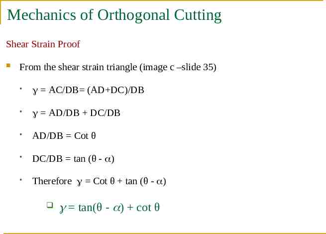
Mechanics of Orthogonal Cutting Shear Strain Proof From the shear strain triangle (image c –slide 35) AC/DB (AD DC)/DB AD/DB DC/DB AD/DB Cot θ DC/DB tan (θ - ) Therefore Cot θ tan (θ - ) tan(θ - ) cot θ
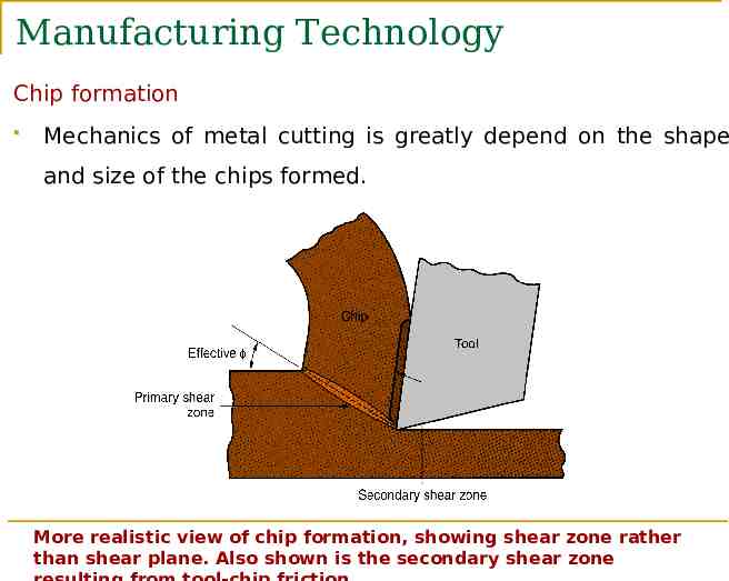
Manufacturing Technology Chip formation Mechanics of metal cutting is greatly depend on the shape and size of the chips formed. More realistic view of chip formation, showing shear zone rather than shear plane. Also shown is the secondary shear zone
Manufacturing Technology Four Basic Type of Chips in Machining are Discontinuous chip Continuous chip Continuous chip with Built-up Edge (BUE) Serrated chip
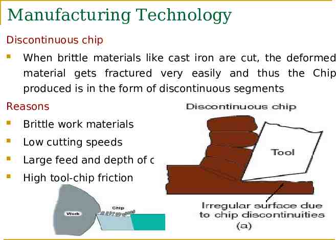
Manufacturing Technology Discontinuous chip When brittle materials like cast iron are cut, the deformed material gets fractured very easily and thus the Chip produced is in the form of discontinuous segments Reasons Brittle work materials Low cutting speeds Large feed and depth of cut High tool‑chip friction
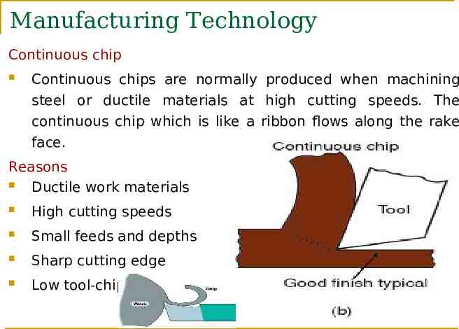
Manufacturing Technology Continuous chip Continuous chips are normally produced when machining steel or ductile materials at high cutting speeds. The continuous chip which is like a ribbon flows along the rake face. Reasons Ductile work materials High cutting speeds Small feeds and depths Sharp cutting edge Low tool‑chip friction
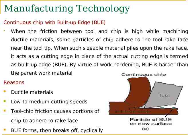
Manufacturing Technology Continuous chip with Built-up Edge (BUE) When the friction between tool and chip is high while machining ductile materials, some particles of chip adhere to the tool rake face near the tool tip. When such sizeable material piles upon the rake face, it acts as a cutting edge in place of the actual cutting edge is termed as built up edge (BUE). By virtue of work hardening, BUE is harder than the parent work material Reasons Ductile materials Low‑to‑medium cutting speeds Tool-chip friction causes portions of chip to adhere to rake face BUE forms, then breaks off, cyclically
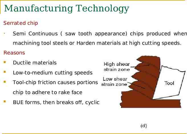
Manufacturing Technology Serrated chip Semi Continuous ( saw tooth appearance) chips produced when machining tool steels or Harden materials at high cutting speeds. Reasons Ductile materials Low‑to‑medium cutting speeds Tool-chip friction causes portions of chip to adhere to rake face BUE forms, then breaks off, cyclically
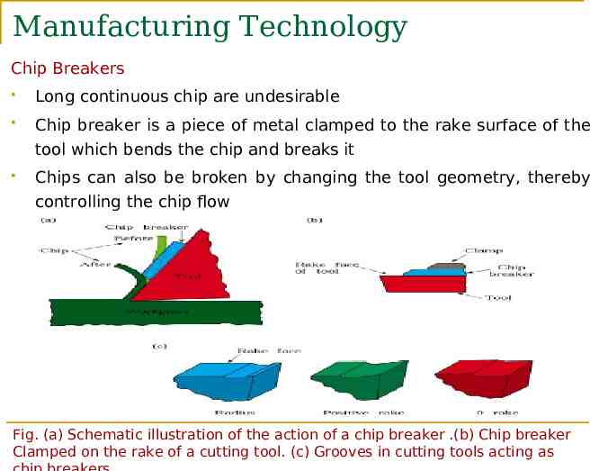
Manufacturing Technology Chip Breakers Long continuous chip are undesirable Chip breaker is a piece of metal clamped to the rake surface of the tool which bends the chip and breaks it Chips can also be broken by changing the tool geometry, thereby controlling the chip flow Fig. (a) Schematic illustration of the action of a chip breaker .(b) Chip breaker Clamped on the rake of a cutting tool. (c) Grooves in cutting tools acting as
Force & Velocity Relationships and the Merchant Equation
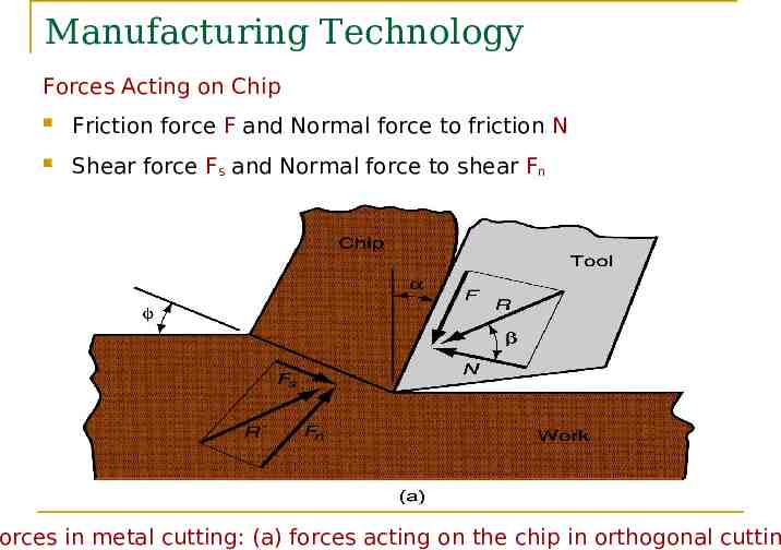
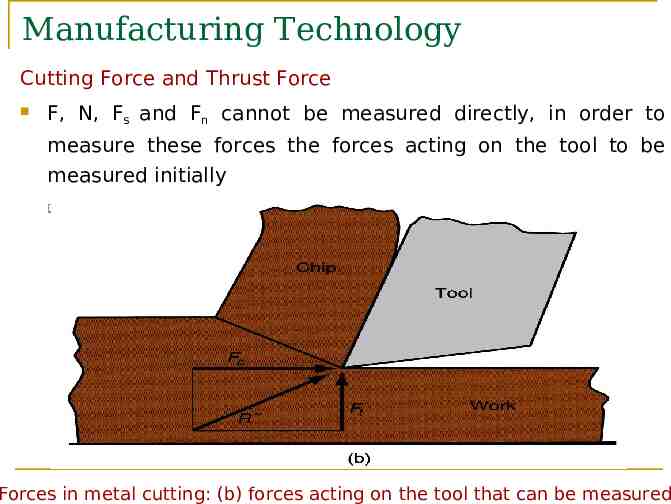
Manufacturing Technology Forces Acting on Chip Friction force F and Normal force to friction N Shear force Fs and Normal force to shear Fn Forces in metal cutting: (a) forces acting on the chip in orthogonal cutting
Manufacturing Technology Cutting Force and Thrust Force F, N, Fs and Fn cannot be measured directly, in order to measure these forces the forces acting on the tool to be measured initially Cutting force Fc and Thrust force Ft Forces in metal cutting: (b) forces acting on the tool that can be measured
Manufacturing Technology Resultant Forces Vector addition of F and N resultant R Vector addition of Fs and Fn resultant R' Forces acting on the chip must be in balance: R' must be equal in magnitude to R R’ must be opposite in direction to R R’ must be collinear with R
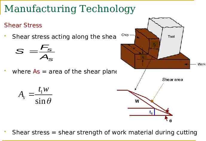
Manufacturing Technology Shear Stress Shear stress acting along the shear plane Fs S As where As area of the shear plane t1w As sin Shear stress shear strength of work material during cutting
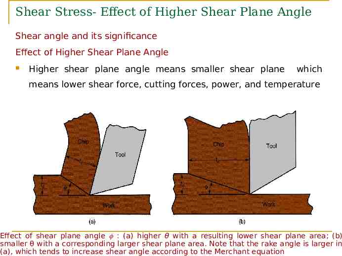
Shear Stress- Effect of Higher Shear Plane Angle Shear angle and its significance Effect of Higher Shear Plane Angle Higher shear plane angle means smaller shear plane which means lower shear force, cutting forces, power, and temperature Effect of shear plane angle : (a) higher θ with a resulting lower shear plane area; (b) smaller θ with a corresponding larger shear plane area. Note that the rake angle is larger in (a), which tends to increase shear angle according to the Merchant equation
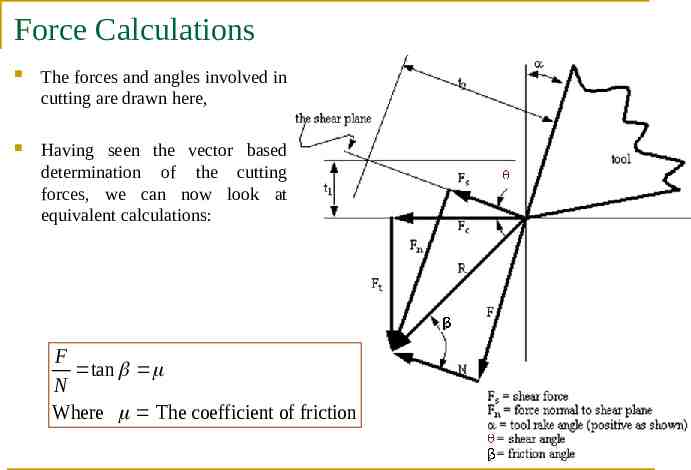
Force Calculations The forces and angles involved in cutting are drawn here, Having seen the vector based determination of the cutting forces, we can now look at equivalent calculations: F tan N Where The coefficient of friction
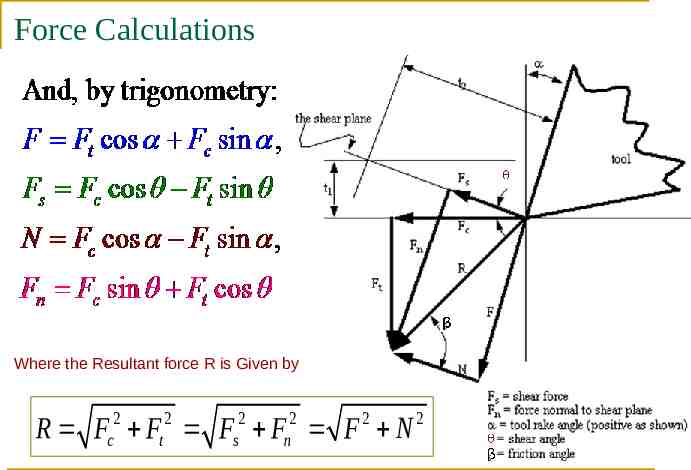
Force Calculations Where the Resultant force R is Given by R Fc2 Ft 2 Fs2 Fn2 F 2 N 2
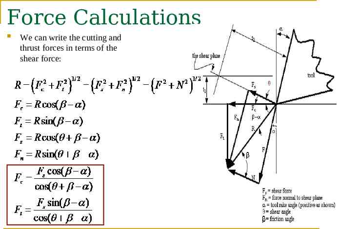
Force Calculations We can write the cutting and thrust forces in terms of the shear force:
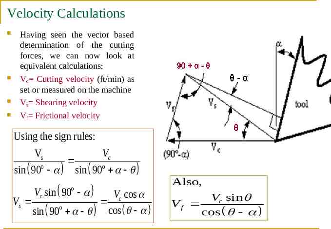
Velocity Calculations Having seen the vector based determination of the cutting forces, we can now look at equivalent calculations: Vc Cutting velocity (ft/min) as set or measured on the machine Vs Shearing velocity Vf Frictional velocity Using the sign rules: Vs Vc o sin 90 sin 90o Vc sin 90 o Vc cos Vs o sin 90 cos Also, Vf Vc sin cos
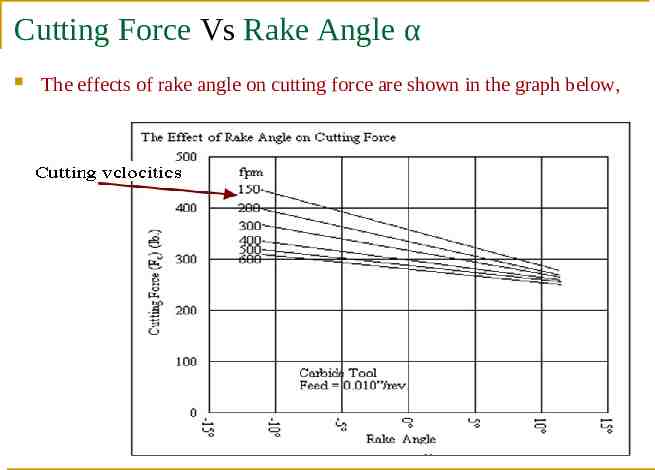
Cutting Force Vs Rake Angle α The effects of rake angle on cutting force are shown in the graph below,
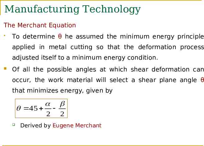
Manufacturing Technology The Merchant Equation To determine θ he assumed the minimum energy principle applied in metal cutting so that the deformation process adjusted itself to a minimum energy condition. Of all the possible angles at which shear deformation can occur, the work material will select a shear plane angle θ that minimizes energy, given by 45 2 2 Derived by Eugene Merchant
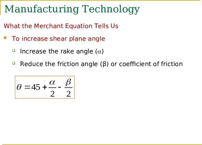
Manufacturing Technology What the Merchant Equation Tells Us To increase shear plane angle Increase the rake angle ( ) Reduce the friction angle (β) or coefficient of friction 45 2 2
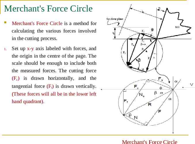
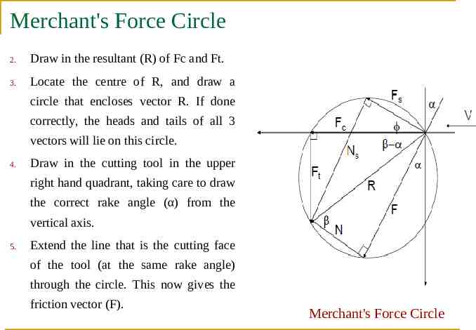
Merchant's Force Circle Merchant's Force Circle is a method for calculating the various forces involved in the cutting process. 1. Set up x-y axis labeled with forces, and the origin in the centre of the page. The scale should be enough to include both the measured forces. The cutting force (Fc) is drawn horizontally, and the tangential force (Ft) is drawn vertically. (These forces will all be in the lower left hand quadrant). Merchant's Force Circle
Merchant's Force Circle 2. Draw in the resultant (R) of Fc and Ft. 3. Locate the centre of R, and draw a circle that encloses vector R. If done correctly, the heads and tails of all 3 vectors will lie on this circle. 4. Draw in the cutting tool in the upper right hand quadrant, taking care to draw the correct rake angle (α) from the vertical axis. 5. Extend the line that is the cutting face of the tool (at the same rake angle) through the circle. This now gives the friction vector (F). Merchant's Force Circle
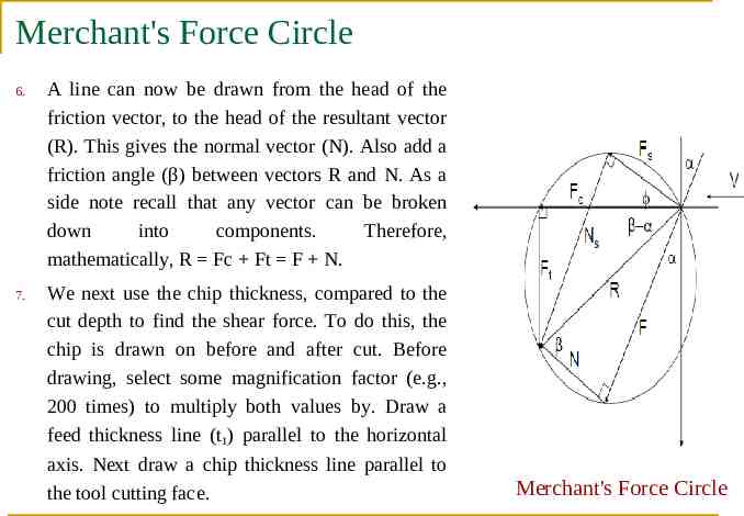
Merchant's Force Circle 6. A line can now be drawn from the head of the friction vector, to the head of the resultant vector (R). This gives the normal vector (N). Also add a friction angle (β) between vectors R and N. As a side note recall that any vector can be broken down into components. Therefore, mathematically, R Fc Ft F N. 7. We next use the chip thickness, compared to the cut depth to find the shear force. To do this, the chip is drawn on before and after cut. Before drawing, select some magnification factor (e.g., 200 times) to multiply both values by. Draw a feed thickness line (t1) parallel to the horizontal axis. Next draw a chip thickness line parallel to the tool cutting face. Merchant's Force Circle
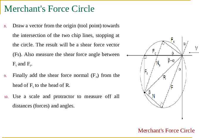
Merchant's Force Circle 8. Draw a vector from the origin (tool point) towards the intersection of the two chip lines, stopping at the circle. The result will be a shear force vector (Fs). Also measure the shear force angle between Fs and Fc. 9. Finally add the shear force normal (Fn) from the head of Fs to the head of R. 10. Use a scale and protractor to measure off all distances (forces) and angles. Merchant's Force Circle
Manufacturing Technology Power and Energy Relationships There are a number of reasons for wanting to calculate the power consumed in cutting. These numbers can tell us how fast we can cut, or how large the motor on a machine must be. Having both the forces and velocities found with the Merchant for Circle, we are able to calculate the power, The power to perform machining can be computed from: Pc Fc . Vc in kw Pc Fc . Vc / 33,000 in HP where Pc cutting power in KW Fc cutting force in KN Vc cutting speed in m/min
Manufacturing Technology Power and Energy Relationships There are a number of reasons for wanting to calculate the power consumed in cutting. These numbers can tell us how fast we can cut, or how large the motor on a machine must be. Having both the forces and velocities found with the Merchant for Circle, we are able to calculate the power, The power to perform machining can be computed from: Pc Fc . Vc in kw Pc Fc . Vc / 33,000 in HP where Pc cutting power in KW Fc cutting force in KN Vc cutting speed in m/min
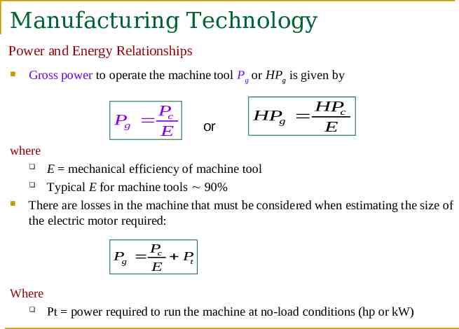
Manufacturing Technology Power and Energy Relationships Gross power to operate the machine tool Pg or HPg is given by P Pg c E or HPc HPg E where E mechanical efficiency of machine tool Typical E for machine tools 90% There are losses in the machine that must be considered when estimating the size of the electric motor required: Pg Pc Pt E Where Pt power required to run the machine at no-load conditions (hp or kW)
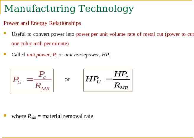
Manufacturing Technology Power and Energy Relationships Useful to convert power into power per unit volume rate of metal cut (power to cut one cubic inch per minute) Called unit power, Pu or unit horsepower, HPu Pc PU RMR or HPc HPU RMR where RMR material removal rate
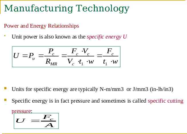
Manufacturing Technology Power and Energy Relationships Unit power is also known as the specific energy U Pc Fc Vc Fc U Pu RMR Vc t1 w t1 w Units for specific energy are typically N‑m/mm3 or J/mm3 (in‑lb/in3) Specific energy is in fact pressure and sometimes is called specific cutting pressure: U Fc A
Manufacturing Technology Cutting Temperature Approximately 98% of the energy in machining is converted into heat This can cause temperatures to be very high at the tool‑chip The remaining energy (about 2%) is retained as elastic energy in the chip High cutting temperatures Reduce tool life Produce hot chips that pose safety hazards to the machine operator Can cause inaccuracies in part dimensions due to thermal expansion of work material
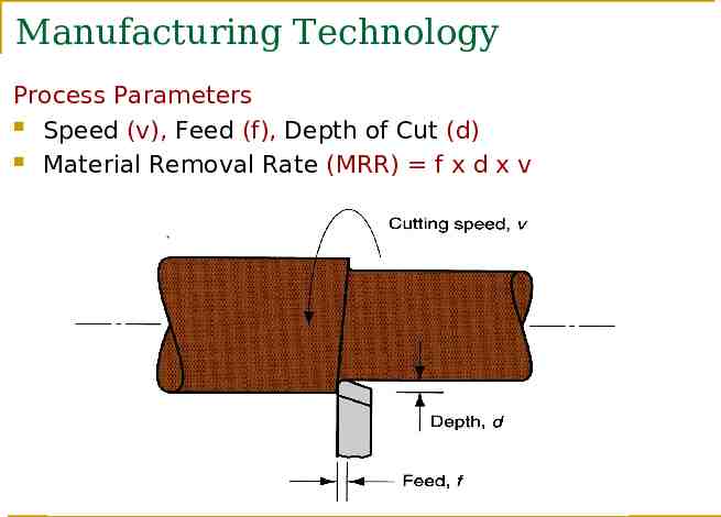
Manufacturing Technology Process Parameters Speed (v), Feed (f), Depth of Cut (d) Material Removal Rate (MRR) f x d x v
Manufacturing Technology Shear angle and its significance Shear angle(θ) is the angle made by the shear plane with the cutting speed vector. Shear angle is very important parameter I metal cutting. Higher the shear angle, better is the cutting performance. In metal cutting it is observed that a higher rake angles give rise to higher shear angles
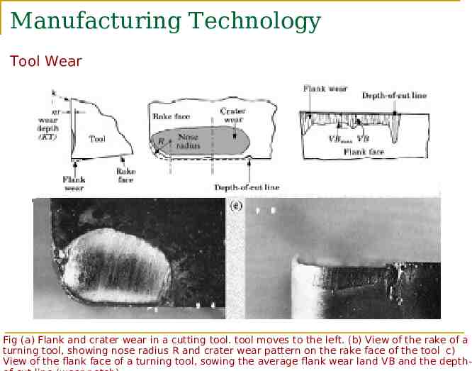
Manufacturing Technology Tool Wear Tools get worn out due to long term usage Types of Tool Wear Flank wear (VB) It occurs on the relief face of the tool and the side relief angle. Crater wear (KT) It occurs on the rake face of the tool. Notch wear or Chipping (VN) Breaking away of a small piece from the cutting edge of the tool
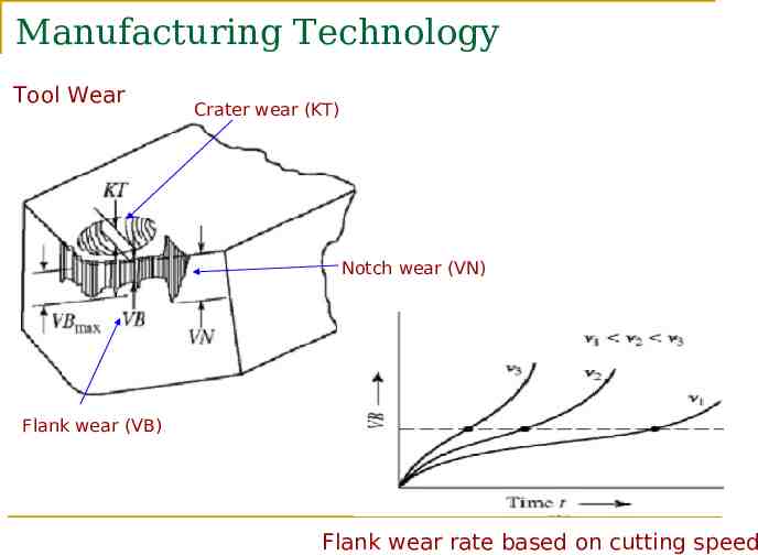
Manufacturing Technology Tool Wear Crater wear (KT) Notch wear (VN) Flank wear (VB) Flank wear rate based on cutting speed
Manufacturing Technology Tool Wear Fig (a) Flank and crater wear in a cutting tool. tool moves to the left. (b) View of the rake of a turning tool, showing nose radius R and crater wear pattern on the rake face of the tool c) View of the flank face of a turning tool, sowing the average flank wear land VB and the depth-
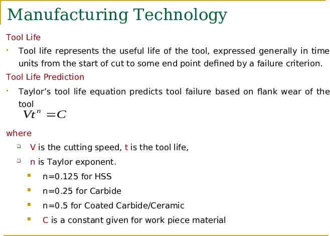
Manufacturing Technology Tool Life Tool life represents the useful life of the tool, expressed generally in time units from the start of cut to some end point defined by a failure criterion. Tool Life Prediction Taylor’s tool life equation predicts tool failure based on flank wear of the tool Vt n C where V is the cutting speed, t is the tool life, n is Taylor exponent. n 0.125 for HSS n 0.25 for Carbide n 0.5 for Coated Carbide/Ceramic C is a constant given for work piece material
Manufacturing Technology Machinability Machinability is a system property that indicates how easy a material can be machined at low cost. Good machinabililty may mean one or more of the following: cutting with minimum energy, minimum tool wear, good surface finish, etc. Quantitative measures of machinability Machinability index: an average rating stated in comparison with reference materials. This measure can be misleading. Tool life: service time in minutes or seconds to total failure by chipping or cracking of the tool at certain cutting speed, or the volume of material removed before total failure. Surface finish produced at standardized cutting speeds and feeds. Others based on cutting force, power, temperature, or chip formation.
Manufacturing Technology Machinable Materials Good machinable materials should have the following properties Low ductility, low strain-hardening exponent (n), low fracture toughness. Low shear strength (low TS), low hardness. A strong metallurgical bond (adhesion) between tool and work piece is undesirable when it weakens the tool material. Very hard compounds, such as some oxides, all carbides, many inter metallic compounds, and elements such as silicon, embedded in the work piece material accelerate tool wear, thus should be avoided. Inclusions that soften at high temperatures are beneficial. High thermal conductivity is helpful.
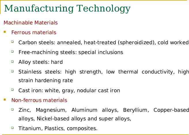
Manufacturing Technology Machinable Materials Ferrous materials Carbon steels: annealed, heat-treated (spheroidized), cold worked Free-machining steels: special inclusions Alloy steels: hard Stainless steels: high strength, low thermal conductivity, high strain hardening rate Cast iron: white, gray, nodular cast iron Non-ferrous materials Zinc, Magnesium, Aluminum alloys, Beryllium, Copper-based alloys, Nickel-based alloys and super alloys, Titanium, Plastics, composites.
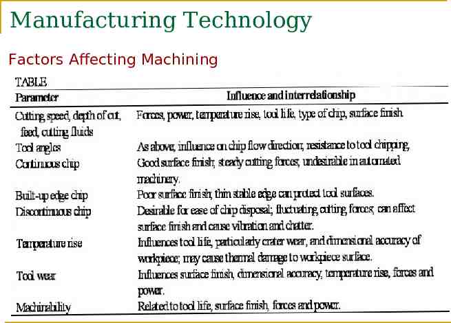
Manufacturing Technology Factors Affecting Machining
Manufacturing Technology Cutting Fluids A fluid which is used in machining as well as abrasive machining processes to reduce friction and tool wear Function of cutting fluids Lubrication Cooling Chip removal Types Straight Oil (Petroleum based oils) Soluble Oil (water based oils)
Manufacturing Technology Problems Refer P.C. Sharma volume-II book Page No – 33 to 46
END