Low Latency Networking Glenford Mapp Digital Technology Group Computer


56 Slides97.50 KB
Low Latency Networking Glenford Mapp Digital Technology Group Computer Laboratory http://www.cl.cam.ac.uk/Research/DTG/ gem11
What is Latency? The time taken to send a unit of data between two points in a network A low latency network is a network in which the design of the hardware, systems and protocols are geared towards minimizing the time taken to move units of data between any two points on that network
Throughput Number of bytes of data that is transferred per second between two points Doesn’t high throughput imply low latency? Not necessarily – A bus vs a car travelling along a section of road Which has the higher throughput? Which has the lower latency?
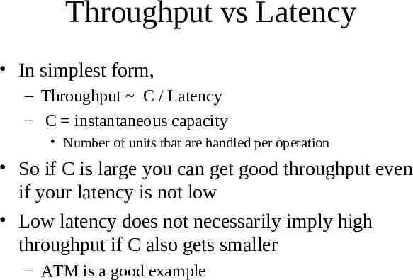
Throughput vs Latency In simplest form, – Throughput C / Latency – C instantaneous capacity Number of units that are handled per operation So if C is large you can get good throughput even if your latency is not low Low latency does not necessarily imply high throughput if C also gets smaller – ATM is a good example
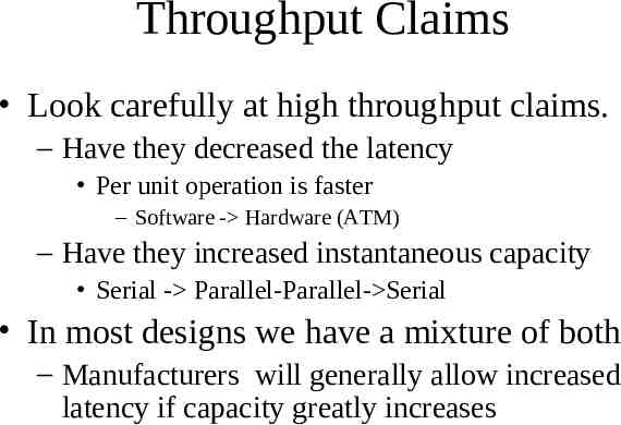
Throughput Claims Look carefully at high throughput claims. – Have they decreased the latency Per unit operation is faster – Software - Hardware (ATM) – Have they increased instantaneous capacity Serial - Parallel-Parallel- Serial In most designs we have a mixture of both – Manufacturers will generally allow increased latency if capacity greatly increases
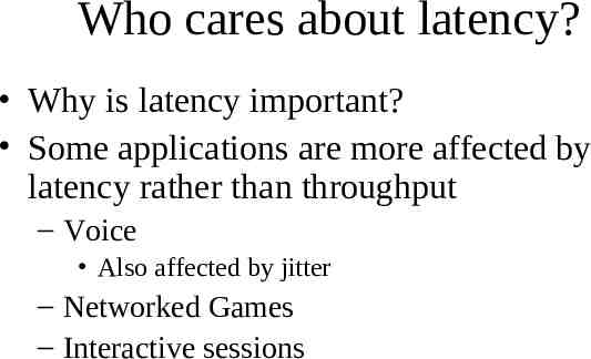
Who cares about latency? Why is latency important? Some applications are more affected by latency rather than throughput – Voice Also affected by jitter – Networked Games – Interactive sessions
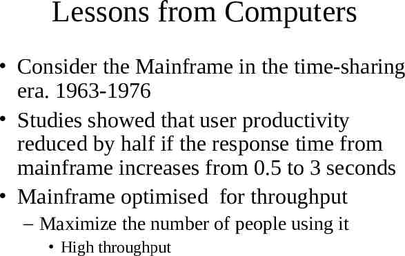
Lessons from Computers Consider the Mainframe in the time-sharing era. 1963-1976 Studies showed that user productivity reduced by half if the response time from mainframe increases from 0.5 to 3 seconds Mainframe optimised for throughput – Maximize the number of people using it High throughput
Lessons from Computers But as more people logged on the slower the machine became and by noon the response time would increase markedly so user productivity would fall Key factor in the development of PCs Famous saying – I love the Alto (first PC) because it does not run faster at night!
A look at the Internet Not really designed for low latency Designed to be adaptable and robust But the new applications we want the Internet to support need low latency – Web servers – Voice over IP – Networked Games, etc
Components of Network Latency Hardware – Different hardware capacities and limitations Ethernet – variable packet size; max 1500 ATM – 53 bytes uses fixed cells Network Routers and Switches – Queueing strategies – Overload/ Congestion strategy
Components of Network Latency System Latency – Moving the packet between the application and the network interface – OS latency The operating system handling the packet – Application Latency Application must acquire resources (e.g. CPU) in order to send or consume data
Traditional Networking – A closer look Look at a packet being received by the host machine and delivered up to the application At the lowest level, packet enters the network interface card (NIC) – ends up in a buffer or fifo on the card. Card generates an interrupt.
Tradition Networking cont’d Interrupt Handler runs, data is moved into a system buffer in main memory. Packet is placed on a receive queue – In Linux there is one network receive queue Packets from all the network interfaces are placed on that queue Packet is marked for system processing – Interrupt Handler ends
Traditional Networking cont’d System processing – Packet is taken up the protocol stack IP processing ; TCP processing – Connection information associated with the packet is used to find the corresponding socket Socket Src (IPaddr, TCP port) , Dest (IPaddr, TCP port)
Traditional Networking cont’d Queue the packet on the socket structure and see if any application threads are waiting for incoming data If so, copy the data from system buffer to the user buffer and wake up the thread Application has to wait until it gets the CPU to consume data
Analysis of Traditional Networking Interrupt systems – potentially infinite latency – Processing of packets in the queue is affected by the rate of incoming packets Copying data adds to latency OS sits between two worlds – It de-multiplexes the packet and decides its final destination – It also ensures that the relevant application is scheduled to receive the data. This is called application synchronisation
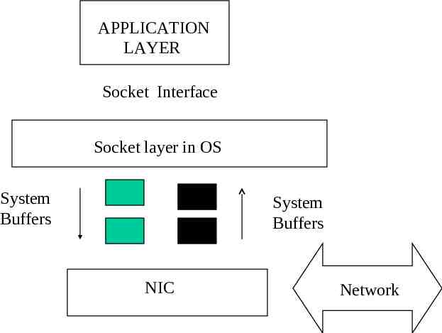
APPLICATION LAYER Socket Interface Socket layer in OS System Buffers System Buffers NIC Network
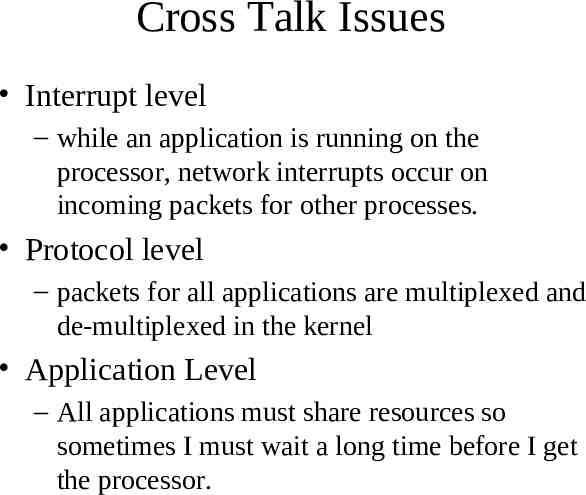
Cross Talk Issues Interrupt level – while an application is running on the processor, network interrupts occur on incoming packets for other processes. Protocol level – packets for all applications are multiplexed and de-multiplexed in the kernel Application Level – All applications must share resources so sometimes I must wait a long time before I get the processor.
Some ways to improve Traditional Networking User level network interfaces – UNET - Matt Walsh (1995-1998) Zero copy architectures – Virtual memory mapping techniques Vertical Partitioning of Operating Systems
UNET Application has an interface to talk directly to a network device Doesn’t involve the kernel in things like protocol processing, etc. Uses per application message queues to send and receive data Novel idea at the time – complicates what applications need to do
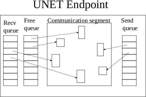
UNET Endpoint Recv Free queue queue Communication segment Send queue
Zero-Copy Architecture No need to copy data up to the application DMA from network buffers in NIC card straight into system buffers Use VM techniques to map the relevant system buffers into the address space of the application
Vertical Partitioning of the OS So UNET gave applications an abstract network card so there was less multiplexing of data. Why not go all the way and do more partitioning of OS resources So CPU is carefully partitioned, file systems and disk devices also carefully partitioned
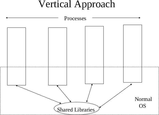
Pegasus project - Cambridge Studied system support for multimedia applications Developed a new operating system called Nemesis which adopted a vertical approach – Most of the operating system functions were in shared libraries which executed in the user’s process space – System-wide page table, so no copying
Vertical Approach Processes Shared Libraries Normal OS
Why haven’t these ideas been universally implemented Some were explored – VIA is a hardware idea based on UNET – Replace PCI bus – Devices have receive, send and completion queues and are connected along a high-speed serial bus – One or two products out there but fell out of favour Infiniband - now popular – extension of VIA
Ideas not universal Zero copy and VM ideas explored in some Operating Systems, e.g. the Spring OS by Sun. Some ideas made their way into Solaris. Windows 2000 and XP, via Mach and NT Nemesis was too radical for prime time – QoS ideas have been taken up by others
But the real reason was. That processor and network speeds have been increasing fast enough to keep traditional networking in the picture. If you simply want to browse the Web and read email, then it is OK However, there is a looming problem
Network speeds still going up! We have gone from 10 Mbps in 1987 to 10G in 2004 and beyond. Processor not be able to keep up – Interrupt rate is phenomenal Buses like the PCI bus cannot keep up – Move to PCI Express (Switch Fabric) Workstation can presently saturate the network but the tide is rapidly turning! Network traffic will soon be able to cripple your PC
Need a system that is less interrupt-dependent Two main approaches – No OS processing whatsoever including no interrupts data is moved by hardware OS is used to setup where the data is moved to – Apply more processing power but target it on the network interface
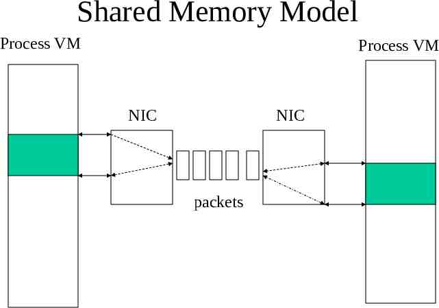
Shared Memory Model Data transfer is accomplished by writing to memory addresses in the local address space of the process This data is captured by the local network card and serialized into packets which are transferred over the network to the remote machine which writes the data to remote addresses.
How does it actually work? A region of the local address space of the process is mapped to an IO region on the card. That mapping is usually made using standard memory-mapping techniques. – In Unix the mmap call is used. Same thing is done on the remote side
Shared Memory Model Process VM Process VM NIC NIC packets
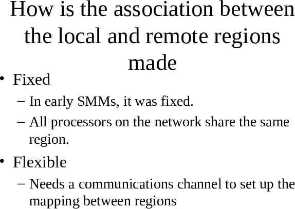
How is the association between the local and remote regions made Fixed – In early SMMs, it was fixed. – All processors on the network share the same region. Flexible – Needs a communications channel to set up the mapping between regions
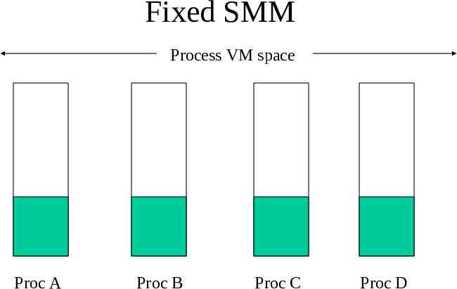
Fixed SMM Process VM space Proc A Proc B Proc C Proc D
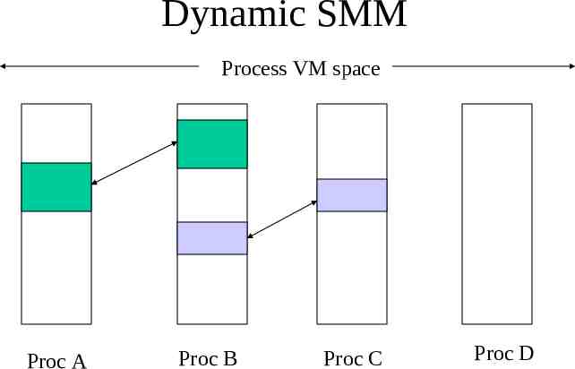
Dynamic SMM Process VM space Proc A Proc B Proc C Proc D
SMM Been around a long time – Used to communicate between processors in a cluster. The SMM is divided into pages, some of which can be mapped between two processes and the other set can be mapped globally
Problems with SMM Since no interrupts are involved and the OS is no longer in the loop, it’s hard to inform the remote node that data has been sent and is waiting to be read Major problem is therefore not the transfer, but application synchronization
Applications Synchronization Solutions Polling: – the receiver keeps polling certain addresses to see if a data transfer has occurred – This is expensive (wasting local CPU) and only relevant if there is a real chance of a data transfer. – Could be used to provide to provide a form of distributed synchronization - spinning on a remote address
Application Synchronization Solutions VM signalling – Pagefault or access violations – Example: page is only mapped locally when there is data to be read. If I access the page when there is no data, then a pagefault occurs and I am blocked until the owner writes to the page
VM Signalling If I wish to read and there is data to be read then the page is mapped into my address space read-only. If I attempt to write to the page, a pagefault occurs and I am blocked until I can acquire the write lock for the page Not scalable, too closely coupled to the VM system
Out-of-Band signaling Use a separate channel outside the data transfer region to signal that data has been transferred. For example, writing to a special set of addresses would cause an interrupt to be generated at the remote end
Out-of-Band Signalling So you would transfer the data by writing to your local address After you then wrote to a special address associated with that memory region An interrupt occurs on the other side and the OS works out which buffer you are referring to and wakes up the waiting process
Out-of-Band Signalling Out-of-Band Signalling still involves the processor to achieve application synchronization Adds the overall transfer latency – Ex. Memory Channel data transfer 2.9 us acquire spin lock 120 us Increases the expense of the NIC
History of SMM Used to be extremely proprietary DEC Memory Channel best known – Used a fixed shared memory region of 512 MB divided into 64K pages each page being 8K – Very versatile, can share pages between one or more processes. Use broadcast facilities – Average latencies 10-25 us
SCI - Scalable Coherent Interface IEEE Standard 1956-1992 Uses high speed unidirectional links – Parallel links 16 bits, 500 Mhz (8 Gbs) – Serial G-Link technology (1Gbs) Packet-based transfer – header - 16 bytes; data 0, 16, 64 or 256 bytes – queue and signal interrupts
SCI cont’d Can do cache-coherency (optional) Latency 10 us Modern cards uses 64bit and 66 MHz buses (5.33 Gbits/s) Big player: Dolphin Interconnect – Sun uses their boards to build megaservers
Processor Intensive Approach PIA We offload networking by using a processor on the NIC Myrinet - most well-known exponent – Full duplex data links 2 Gbits/s – Bus 64-bit 133Hz PCI-X bus – PC - 255 Mhz RISC & Memory
Myrinet con’t Packet-based – Header, packet type, payload Host Computer controls the NIC – runs a MCP program Myrinet controls around 39 % of the cluster market
Performance Latency around 6.3 us – Climbs to over 100 us over 10000 bytes One way throughput 248 MB/s – Messages over a 1000 bytes Two way throughput 489 MB/s – Message over 10000 bytes Throughput between Unix processes on different hosts – 1.98 Gbits (uni) 3.9 Gbits/s (bi)
Comparing SCI and Myrinet Latency are about the same SCI much faster for cluster of 8 or less – but slows exponentially as the number of PCs increases Myrinet is better for large systems 64 Software appears more complete with Myrinet
Recent developments in Low Latency Systems Collapsed LAN project (CLAN) – 1997 - 2002, AT&T Laboratories-Cambridge – project originally centred around using fibre technology throughout the building – remoting PCs; just have mouse, keyboard and display in your office and put the PC in the server room – bought some SCI cards and got some systems going
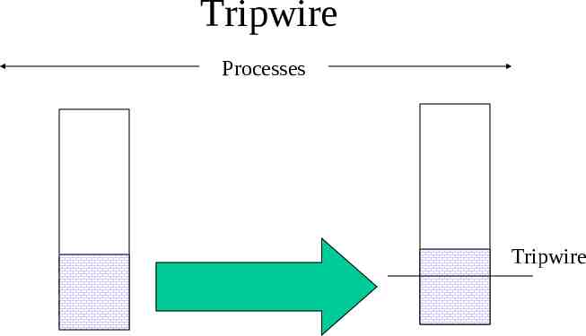
CLAN project Faced the application synchronization problem Came up with a novel solution called Tripwire – in-band synchronization – an event is signalled on the receiver when data is written to a special address in the data region during the data transfer
Tripwire Processes Tripwire
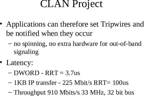
CLAN Project Applications can therefore set Tripwires and be notified when they occur – no spinning, no extra hardware for out-of-band signaling Latency: – DWORD - RRT 3.7us – 1KB IP transfer - 225 Mbit/s RRT 100us – Throughput 910 Mbits/s 33 MHz, 32 bit bus
Will Low latency ever make it into the Main Stream Some low latency 1 Gigabit/s NICs on the market Unfortunately 1 Gigabit/s market is now in the commodity phase. Real battle is shaping up at 10 Gbit/s market – CLAN project - Level5Networks- Solarflare