Load balancing in IP protocols Author: Sunesh Kumra Supervisor:


24 Slides146.00 KB
Load balancing in IP protocols Author: Sunesh Kumra Supervisor: Prof Raimo Kantola Instructor: Michael Zhidovinov Work was carried out: Nokia Networks, Helsinki Thesis number: 1023 – 2004 Presentation Date: Aug 31, 2004 Load Balancing in IP Protocols.PPT / 14-Aug-2004 / Sunesh Kumra
Table of Contents Introduction Research Problem Stateless Load Balancer Stateful Load Balancer Dynamic Addition and Removal of Nodes Capacity Based Load Balancing Overload Control Conclusion Load Balancing in IP Protocols.PPT / 14-Aug-2004 / Sunesh Kumra
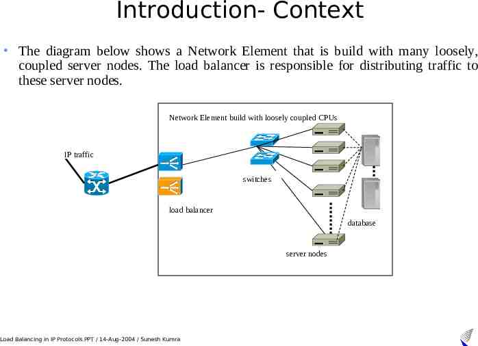
Introduction- Context The diagram below shows a Network Element that is build with many loosely, coupled server nodes. The load balancer is responsible for distributing traffic to these server nodes. Network Element build with loosely coupled CPUs IP traffic switches load balancer database server nodes Load Balancing in IP Protocols.PPT / 14-Aug-2004 / Sunesh Kumra
Research Problem – Requirements The most important functional requirement of the load balancer is to ensure that all the traffic pertaining to one call goes to the same CPS Process Performance: The LB is he single point of entry in the cluster (NE) and hence has to be fast enough without becoming the bottleneck of the cluster. Scalability: More nodes can be added to LB (load balancer) at the run time. A load balancer should be able to scale both statically and dynamically. Awareness of load at the nodes where the traffic is being routed. Ideally, the load balancer must be adaptive. LB should be able to handle failures of internal nodes. The aim is not to make sure that the LB can handle all kinds of faults, but it should be able to handle basic fault situation such as the case when an internal node crashes. Load Balancing in IP Protocols.PPT / 14-Aug-2004 / Sunesh Kumra
Introduction- types of load balancers Network-Based load balancing : This type of load balancing is provided by IP routers and DNS (domain name servers) that service a pool of host machines. For example, when a client resolves a hostname, the DNS can assign a different IP address to each request dynamically based on current load conditions. Network-Layer based load balancing : The load balancer may balance the traffic based on the source IP address and/or port of the incoming IP packet. This type of load balancing does not take into account the contents of the packet, so is not very flexible. Transport-Layer based load balancing : The load balancer may choose to route the entire connection to a particular server. This type of load balancing is very useful if the connections are short-lived and are established frequently. Application-Layer/Middleware based load balancing :This type of load balancing is performed in the application-layer, often on a per-session or perrequest basis. Load Balancing in IP Protocols.PPT / 14-Aug-2004 / Sunesh Kumra
Introduction- classes of load balancers Non-adaptive load balancer: A load balancer can use non-adaptive policies, such as simple round-robin algorithm, hash-based or randomization algorithm. Adaptive load balancer: A load balancer can use adaptive policies that utilize run-time information, such as amount of CPU load on the node to determine the server to route the request to. Load Balancers and Load Distributors are not the same thing. Strictly speaking non-adaptive load balancers are load distributors. Load Balancing in IP Protocols.PPT / 14-Aug-2004 / Sunesh Kumra
Research Problem – categories from LB perspective UDP based protocols TCP based protocols where each session/call lasts for a very long time. TCP based protocol where each session/call is short lived or a mix of short and medium duration Load Balancing in IP Protocols.PPT / 14-Aug-2004 / Sunesh Kumra
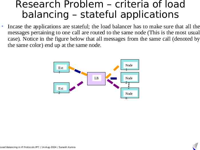
Research Problem – criteria of load balancing – stateful applications Incase the applications are stateful; the load balancer has to make sure that all the messages pertaining to one call are routed to the same node (This is the most usual case). Notice in the figure below that all messages from the same call (denoted by the same color) end up at the same node. Node 1 Ext 1 LB Ext 2 Load Balancing in IP Protocols.PPT / 14-Aug-2004 / Sunesh Kumra Node 2 Node n
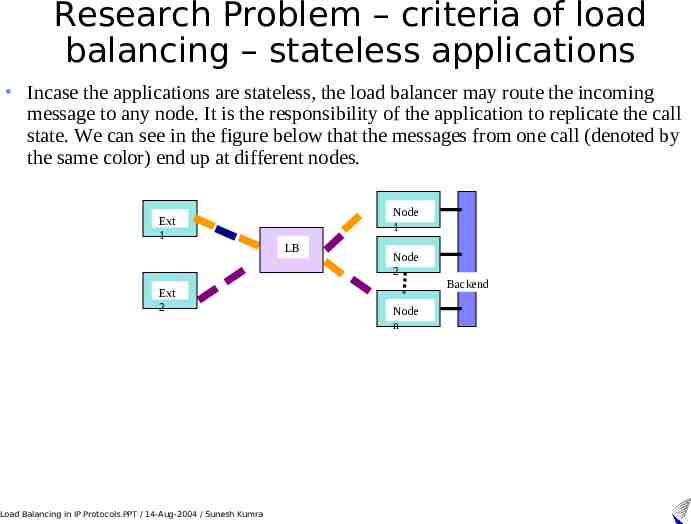
Research Problem – criteria of load balancing – stateless applications Incase the applications are stateless, the load balancer may route the incoming message to any node. It is the responsibility of the application to replicate the call state. We can see in the figure below that the messages from one call (denoted by the same color) end up at different nodes. Ext 1 Ext 2 Load Balancing in IP Protocols.PPT / 14-Aug-2004 / Sunesh Kumra Node 1 LB Node 2 Node n Backend
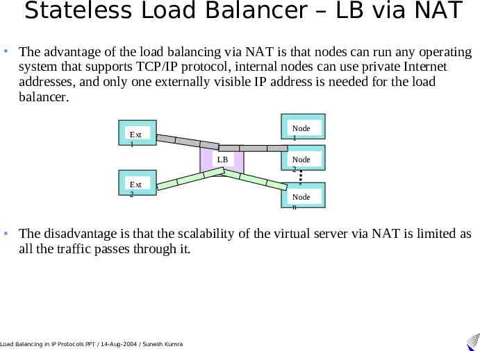
Stateless Load Balancer – LB via NAT The advantage of the load balancing via NAT is that nodes can run any operating system that supports TCP/IP protocol, internal nodes can use private Internet addresses, and only one externally visible IP address is needed for the load balancer. Node 1 Ext 1 LB Ext 2 Node 2 Node n The disadvantage is that the scalability of the virtual server via NAT is limited as all the traffic passes through it. Load Balancing in IP Protocols.PPT / 14-Aug-2004 / Sunesh Kumra
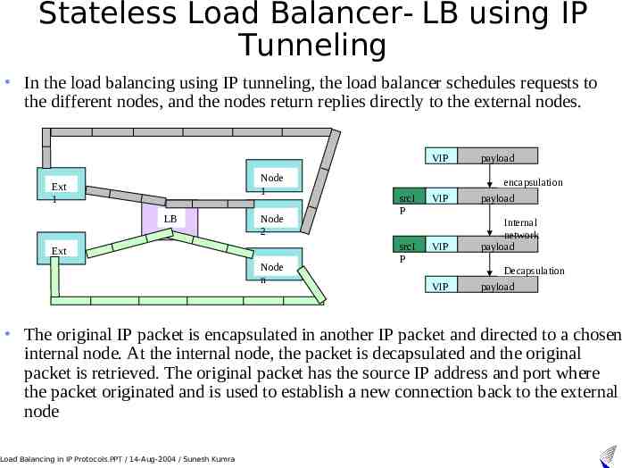
Stateless Load Balancer- LB using IP Tunneling In the load balancing using IP tunneling, the load balancer schedules requests to the different nodes, and the nodes return replies directly to the external nodes. VIP Node 1 Ext 1 LB Ext 2 Node 2 Node n payload encapsulation srcI P VIP payload srcI P VIP Internal network payload Decapsulation VIP payload The original IP packet is encapsulated in another IP packet and directed to a chosen internal node. At the internal node, the packet is decapsulated and the original packet is retrieved. The original packet has the source IP address and port where the packet originated and is used to establish a new connection back to the external node Load Balancing in IP Protocols.PPT / 14-Aug-2004 / Sunesh Kumra
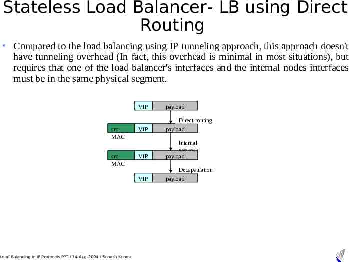
Stateless Load Balancer- LB using Direct Routing Compared to the load balancing using IP tunneling approach, this approach doesn't have tunneling overhead (In fact, this overhead is minimal in most situations), but requires that one of the load balancer's interfaces and the internal nodes interfaces must be in the same physical segment. VIP payload Direct routing src MAC VIP payload src MAC VIP Internal network payload Decapsulation VIP Load Balancing in IP Protocols.PPT / 14-Aug-2004 / Sunesh Kumra payload
Stateful Load Balancer – properties 1/2 For every call instead of calculating the hash we use Round-Robin algorithm, ensuring an even load distribution. For every message we have to read/write from/to the Call State machine. machine Reading from the Call State Machine would be at least twice as many times as writing to it. The Call State Machine may soon become the bottleneck of the load balancer. Call State Machines soon grow to a big size, taking up a lot of memory. Maintaining call state takes a lot of memory. For example in the worst case, if the load balancer is serving 20 000 transactions/second and each transaction has a timeout of 3 minutes then it has to maintain 180 x 20 000 3.6 million states at any time. If every state takes 20 bytes then the 68 MB memory is required just for maintaining call-states The graceful addition and removal of the nodes is also very simple to implement in stateful load balancers. This is because if there were a few nodes added to the cluster, it will not change anything in the Call State Machine for the on-going calls. Load Balancing in IP Protocols.PPT / 14-Aug-2004 / Sunesh Kumra
Stateful Load Balancer– properties 2/2 The stateful load balancer does not scale as well as the stateless load balancer as it has to access a common repository called the Call State machine for reading and writing states. It is difficult to implement redundancy model in stateful load balancers like hotactive standby. The amount of data to be replicated to the standby node depends on the number of calls served by the load balancer. Without providing redundancy for the load balancer, it becomes the single and biggest point of failure for the cluster. To provide a fault tolerant load balancer the call states need to be replicated to a standby unit, the larger the Routing Table the more the data to replicate. In the example that we considered where every state took 20 bytes to store, we would need to replicate a table of size 68 MB, which is an overhead. To replicate these 20 000 states to the standby unit we need a good internal replication mechanism, because 20 000 x 20 390 kilobyte of data would need to be transferred every second. Load Balancing in IP Protocols.PPT / 14-Aug-2004 / Sunesh Kumra
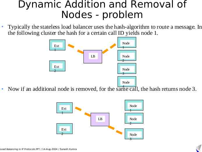
Dynamic Addition and Removal of Nodes - problem Typically the stateless load balancer uses the hash-algorithm to route a message. In the following cluster the hash for a certain call ID yields node 1. Node 1 Ext 1 Node 2 LB Ext 2 Node 3 Node 4 Now if an additional node is removed, for the same call, the hash returns node 3. Node 1 Ext 1 LB Ext 2 Load Balancing in IP Protocols.PPT / 14-Aug-2004 / Sunesh Kumra Node 2 Node 3
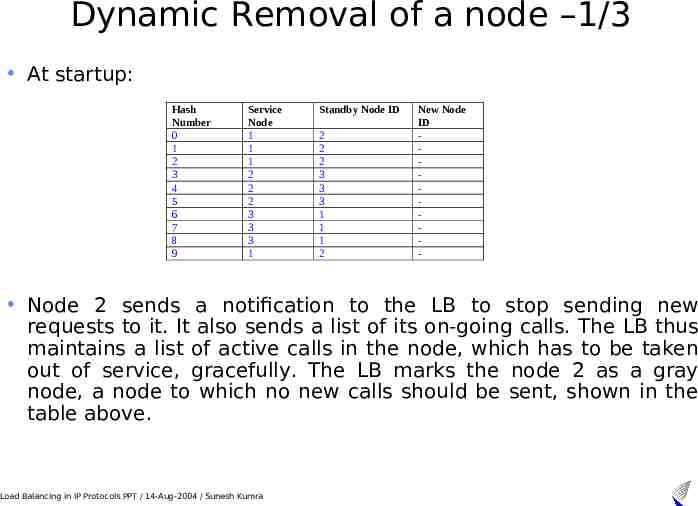
Dynamic Removal of a node –1/3 At startup: Hash Number 0 1 2 3 4 5 6 7 8 9 Service Node 1 1 1 2 2 2 3 3 3 1 Standby Node ID 2 2 2 3 3 3 1 1 1 2 New Node ID - Node 2 sends a notification to the LB to stop sending new requests to it. It also sends a list of its on-going calls. The LB thus maintains a list of active calls in the node, which has to be taken out of service, gracefully. The LB marks the node 2 as a gray node, a node to which no new calls should be sent, shown in the table above. Load Balancing in IP Protocols.PPT / 14-Aug-2004 / Sunesh Kumra
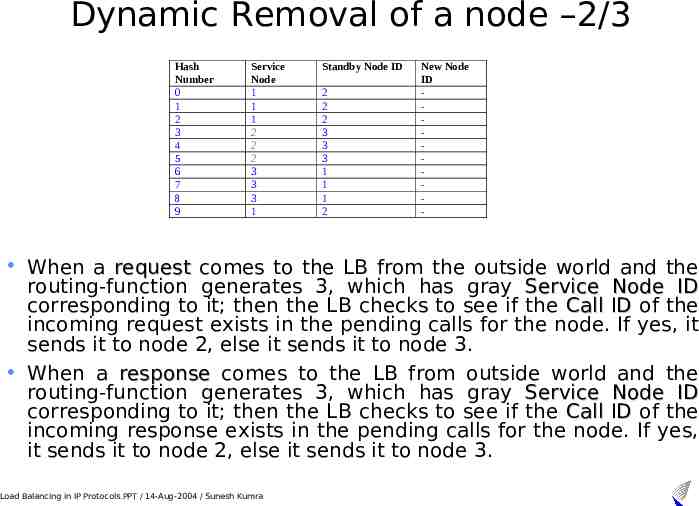
Dynamic Removal of a node –2/3 Hash Number 0 1 2 3 4 5 6 7 8 9 Service Node 1 1 1 2 2 2 3 3 3 1 Standby Node ID 2 2 2 3 3 3 1 1 1 2 New Node ID - When a request comes to the LB from the outside world and the routing-function generates 3, which has gray Service Node ID corresponding to it; then the LB checks to see if the Call ID of the incoming request exists in the pending calls for the node. If yes, it sends it to node 2, else it sends it to node 3. When a response comes to the LB from outside world and the routing-function generates 3, which has gray Service Node ID corresponding to it; then the LB checks to see if the Call ID of the incoming response exists in the pending calls for the node. If yes, it sends it to node 2, else it sends it to node 3. Load Balancing in IP Protocols.PPT / 14-Aug-2004 / Sunesh Kumra
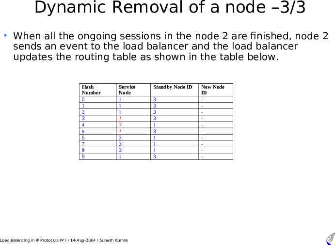
Dynamic Removal of a node –3/3 When all the ongoing sessions in the node 2 are finished, node 2 sends an event to the load balancer and the load balancer updates the routing table as shown in the table below. Hash Number 0 1 2 3 4 5 6 7 8 9 Service Node 1 1 1 1 3 1 3 3 3 1 Load Balancing in IP Protocols.PPT / 14-Aug-2004 / Sunesh Kumra Standby Node ID 3 3 3 3 1 3 1 1 1 3 New Node ID -
Capacity Based Load Balancing – 1/2 In all the discussion above we assumed that the internal nodes had an equal processing capacity. In reality this may not be the case. For example in a cluster running Diameter, SIP and COPS applications, there could be very easily be a case where some nodes are running all the three protocols, some nodes are just running a dedicated protocol, or yet different combinations. The message is that the load balancer cannot distribute traffic to the internal entities assuming that they have equal traffic-handling capacity. Assume that today the standard CPU speed is 1600 MHz, and two year later when we want to add more nodes (new hardware) into the cluster, maybe the commonly available CPU speed then is 2400 MHz, then the traffic cannot be evenly distributed amongst the internal nodes because different nodes have different processing capacity. Hence the need for capacity-based load balancer. Peer Capacity is the parameter of interest for us, for the capacity based load balancer. For example, if a cluster typically has every node with processor with 1600 MHz speed and each node has two processors, and then Peer Capacity may have values from 1 to 4. A value of 1 would mean that the Peer is designed to consume half of one processor and the value of 4 would mean that the Peer should consume both the processors fully. Load Balancing in IP Protocols.PPT / 14-Aug-2004 / Sunesh Kumra
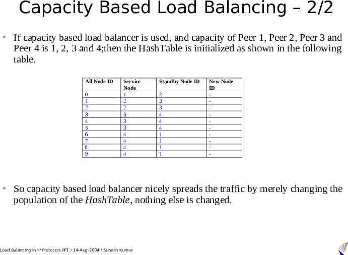
Capacity Based Load Balancing – 2/2 If capacity based load balancer is used, and capacity of Peer 1, Peer 2, Peer 3 and Peer 4 is 1, 2, 3 and 4;then the HashTable is initialized as shown in the following table. All Node ID 0 1 2 3 4 5 6 7 8 9 Service Node 1 2 2 3 3 3 4 4 4 4 Standby Node ID 2 3 3 4 4 4 1 1 1 1 New Node ID - So capacity based load balancer nicely spreads the traffic by merely changing the population of the HashTable, nothing else is changed. Load Balancing in IP Protocols.PPT / 14-Aug-2004 / Sunesh Kumra
Overload Control The arguments in favor and against doing overload control entirely at the load balancer are given below: Advantages: The load balancer is a front door for the cluster. The point of entry is a logical place to make sure that excess traffic does not enters the cluster. There is no proprietary interface required between the Peers and the load balancer for receiving feedback from the nodes. Disadvantages: The processing logic at the load balancer increases and thus would lower it’s performance. The load balancer would have to keep track of load at the internal nodes, therefore bringing in state to it. It is not possible to configure the load balancer to use the metrics of overload provided by the nodes. It is not possible for the load balancer to detect the load at the internal nodes accurately. For example if an internal node is shared such that it is dedicated 20% for COPS, 30 % for Diameter and 50% for SIP. If the load balancer is balancing traffic for, say Diameter and measuring the response time from the Peer to find out how loaded it is, then it might happen that the Diameter Peer starts consuming CPU allocated for other protocols. There is no way that the load balancer can know this. Load Balancing in IP Protocols.PPT / 14-Aug-2004 / Sunesh Kumra
Results and Conclusion-1/2 As IP Telephony becomes more popular and Call Processing Servers become more distributed, the demand for greater scalability and dependability is increasing. Distributed system performance and dependability can degrade significantly, when servers become overloaded by client requests. To alleviate such bottlenecks, load balancer must implement a congestion control algorithm. It should also be possible for the operator or service provider to add extra hardware to the system without interrupting the ongoing traffic. This paper lists four classes of load balancers for IP traffic, which were NetworkBased load balancer, Network-Layer load balancer, Transport-Layer load balancer or the Application Layer based load balancer. All load balancer should follow in one of the above four categories. Performance and scalability are the most important requirements for any load balancer. However providing congestion control and the ability to add or remove servers from the load balancer at run time are very important functionalities as well. A load balancer, which can adapt to changing load in the servers or changing topology, is called as an adaptive load balancer. In the absence of the intelligence to adapt to changing conditions, a load balancer should rather be called as load distributor. Load Balancing in IP Protocols.PPT / 14-Aug-2004 / Sunesh Kumra
Results and Conclusion-2/2 While designing a load balancer care should be taken to keep its functionality as simple as possible. It is very important to have clear requirements before designing a load balancer. This is because a few minor requirements can change the way you want to design a load balancer. For example if there is a requirement that a load balancer must be designed to serve multiple clients which have a short-lived connection, then a transport layer or networking layer load balancer may be a suitable choice. However if a requirement states that a load balancer must be designed to serve some clients that have a very long-lived connection, then an application layer load balancer may be a suitable choice. So the approach towards load balancing solution can vary with every small requirement change. A stateless load balancer has been argued to be better choice than stateful load balancers. A stateful load balancer is easier to design and can provide more flexibility like ease of removing or adding a server to the load balancer and congestion control. The traffic of any protocol should be distributed without modifying or extending the protocol itself. Even if the interoperability for a protocol is not an aim, then also it should be preferred to have a solution, which involves no modification to the existing protocol. Before deciding on a load balancer policy all the alternatives should be considered which are stateful or stateless load balancer on either Layer 3, 4 or 7. The load balancer can further be adaptive or non-adaptive. Load Balancing in IP Protocols.PPT / 14-Aug-2004 / Sunesh Kumra
Thank You Load Balancing in IP Protocols.PPT / 14-Aug-2004 / Sunesh Kumra