ITACS 1. 2. 3. Overview Approach to IS assessment Assessment
41 Slides948.50 KB
ITACS 1. 2. 3. Overview Approach to IS assessment Assessment reporting and ExTRs Overview of auditing IS manufacturers
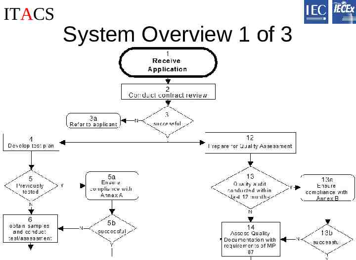
ITACS System Overview 1 of 3
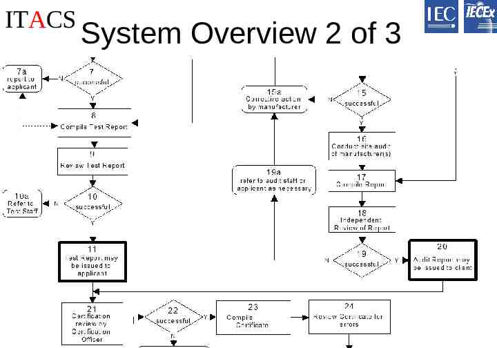
ITACS System Overview 2 of 3
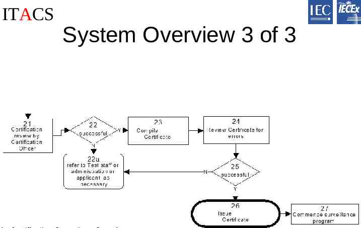
ITACS System Overview 3 of 3
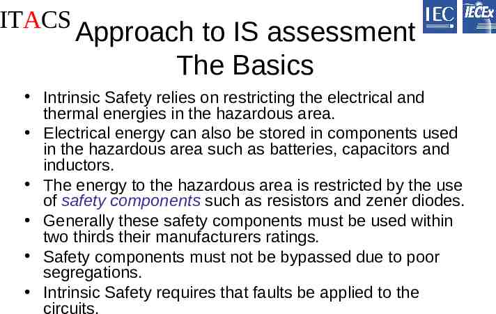
ITACS Approach to IS assessment The Basics Intrinsic Safety relies on restricting the electrical and thermal energies in the hazardous area. Electrical energy can also be stored in components used in the hazardous area such as batteries, capacitors and inductors. The energy to the hazardous area is restricted by the use of safety components such as resistors and zener diodes. Generally these safety components must be used within two thirds their manufacturers ratings. Safety components must not be bypassed due to poor segregations. Intrinsic Safety requires that faults be applied to the circuits.
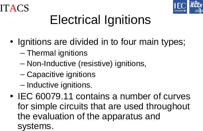
ITACS Electrical Ignitions Ignitions are divided in to four main types; – Thermal ignitions – Non-Inductive (resistive) ignitions, – Capacitive ignitions – Inductive ignitions. IEC 60079.11 contains a number of curves for simple circuits that are used throughout the evaluation of the apparatus and systems.
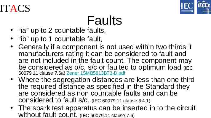
ITACS Faults “ia” up to 2 countable faults, “ib” up to 1 countable fault, Generally if a component is not used within two thirds it manufacturers rating it can be considered to fault and are not included in the fault count. The component may be considered as o/c, s/c or faulted to optimum load (IEC 60079.11 clause 7.6a) Zener 1SMB5913BT3-D.pdf Where the segregation distances are less than one third the required distance as specified in the Standard they are considered as non countable faults and can be considered to fault s/c. (IEC 60079.11 clause 6.4.1) The spark test apparatus can be inserted in to the circuit without fault count. (IEC 60079.11 clause 7.6)
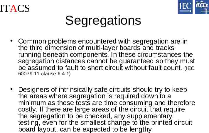
ITACS Segregations Common problems encountered with segregation are in the third dimension of multi-layer boards and tracks running beneath components. In these circumstances the segregation distances cannot be guaranteed so they must be assumed to fault to short circuit without fault count. (IEC 60079.11 clause 6.4.1) Designers of intrinsically safe circuits should try to keep the areas where segregation is required down to a minimum as these tests are time consuming and therefore costly. If there are large areas of the circuit that require the segregation to be checked, any supplementary testing, even for the smallest change to the printed circuit board layout, can be expected to be lengthy .
ITACS Output Parameters The electrical energy in the hazardous area is limited by restricting the voltage and current to acceptable values. This is achieved by safety components such as zener diodes that limit the voltage and current limiting resistors. The maximum values of voltage and current from these power supplies are defined as Ui and Ii and these values are used in the assessment of the hazardous area equipment along with the maximum available output power Po.
ITACS Input Parameters The hazardous area apparatus is assigned a set of input parameters by the manufacturer. The test house will use these input parameters in the evaluation. The apparatus may contain safety components that further limit the energy to specific areas of the circuit.
ITACS Thermal Ignitions Hot surfaces can ignite explosive gases and dusts. The surface temperature of surfaces that are exposed to the explosive gas/dust must be less than the ignition temperature of the gas/dust.
ITACS Thermal Ignitions The surface temperature of components is proportional to the amount of available power. Different components have different temperature characteristics. The same component with a different mounting arrangement is likely to have a different temperature characteristic. The Standard has relaxations for small components and wiring for a Temperature Classification of T4 if the maximum available power does not exceed 1.3W in a 40oC ambient. (IEC 60079.11 clause 6.2.4) Designers of electrical apparatus are recommended to take advantage of this clause as it can significantly reduce testing time and costs.
ITACS Thermal Ignitions The use of safety components such as series current limiting resistors or fuses can be used to reduce the power that may be dissipated into components. Fuses are required to be encapsulated to prevent the explosive atmosphere from contacting the hot filament. The use of encapsulation can also be used to help dissipate the heat from hot components. The encapsulant needs to be robust enough to meet the requirements of the Standard.
ITACS Thermal Ignitions Tests to determine the maximum surface temperature of components can be conducted. These can be time consuming and problems may be encountered due to the small size of these components. Local mounting arrangements can significantly affect the temperature characteristics. Testing in diethyl ether can be problematic. Problems in achieving the correct gas concentrations and detecting an ignition may be expected. Testing also tends to be time consuming and costly.
ITACS Non inductive (Resistive) Ignitions The combination of the voltage and current from the IS power supply located in the safe area must not be capable of causing an ignition. The hazardous area apparatus or system may introduce the scenario where separately certified power supplies may be interconnected or hazardous area apparatus may contain additional sources of power such as batteries. The combination of all these power supplies must be considered in all possible permutations not only on the resistive ignitions but also on any capacitive or inductive ignitions.
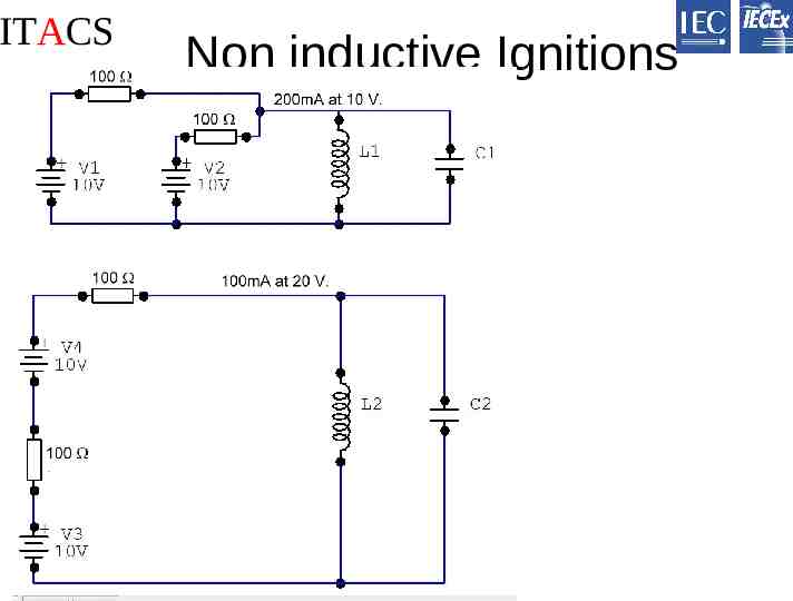
ITACS Non inductive Ignitions
ITACS Capacitive Ignitions IEC 60079.11 provides reference curves that specify the maximum permitted capacitance for specific voltages for the two Groups. The evaluation of hazardous area capacitive circuits is complicated by voltage enhancing and voltage inverting circuits which should be taken into account. LCD modules often contain voltage enhancing circuits. These can cause significant problems with the capacitive evaluation.
ITACS Capacitive Ignitions The simplest method of carrying out the capacitive assessment is to sum all the capacitance within the apparatus together. This approach can be justified by reference to the segregation clause of the Standard where segregation distances less than one third of the relevant value quoted can be considered as conducting without fault count. Where a track passes beneath a component, the segregation distance can not be guaranteed. The segregation distance must be assumed to be less than one third the minimum required by the Standard and therefore, short circuited between component and track.
ITACS Capacitive Ignitions The advantage of this approach is that segregation distances and fault analyses applied to the printed wiring board can be reduced to a minimum, thus allowing changes to the board without the costly process of reassessing the segregation distances. However, this approach can be very restrictive in the amount of capacitance permitted.
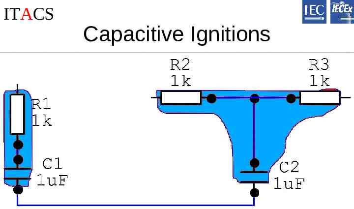
ITACS Capacitive Ignitions A common solution to excessive capacitance is to use adequately rated and segregated current limiting resistors to suppress the discharge from high value capacitors. These resistor protected capacitor networks may then be removed from the cumulative sum of unprotected capacitors. The printed wiring board will have to meet the requirements of the Standard for segregation distances in these resistor protected capacitor nodes, but the segregation distances of the remaining circuits may not require checking.
ITACS Capacitive Ignitions
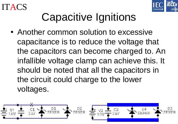
ITACS Capacitive Ignitions Another common solution to excessive capacitance is to reduce the voltage that the capacitors can become charged to. An infallible voltage clamp can achieve this. It should be noted that all the capacitors in the circuit could charge to the lower voltages.
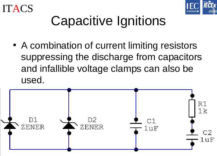
ITACS Capacitive Ignitions A combination of current limiting resistors suppressing the discharge from capacitors and infallible voltage clamps can also be used.
ITACS Capacitive Ignitions To ensure that the combination of unprotected capacitance, resistors protected capacitance and capacitance clamped at lower voltages have a factor of safety not less than 1.5, it may be necessary to test the circuit using the spark test apparatus. The factor of safety is achieved by increasing the voltages by a factor of 1.5 or by using the test gas specified in the standard to provide a factor of safety not less than 1.5.
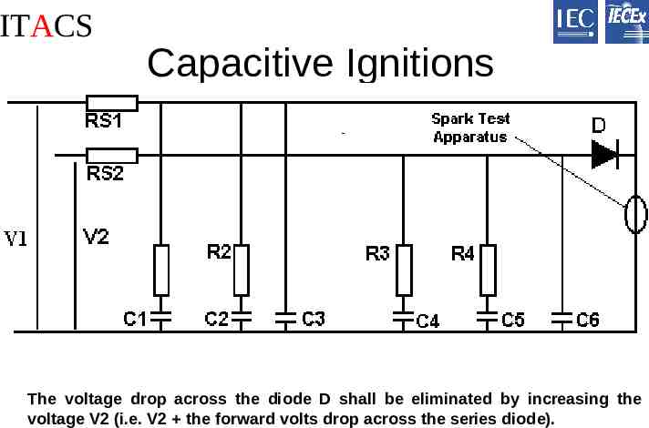
ITACS Capacitive Ignitions The voltage drop across the diode D shall be eliminated by increasing the voltage V2 (i.e. V2 the forward volts drop across the series diode).
ITACS Inductive Ignitions IEC 60079.11 provides reference data that specify the maximum permitted inductance for specific currents for the two Groups. The simplest method of carrying out the inductive assessment is to sum all the inductors within the apparatus together (in series) including the maximum tolerance of the inductors. This approach can be justified by reference to the segregation clause of the standard where segregation distances less than one third of the relevant value quoted can be considered as conducting. Where a track passes beneath a component, the segregation distance can not be guaranteed. The segregation distances are to be assumed to be less than one third the minimum required by the Standard and therefore, conducting.
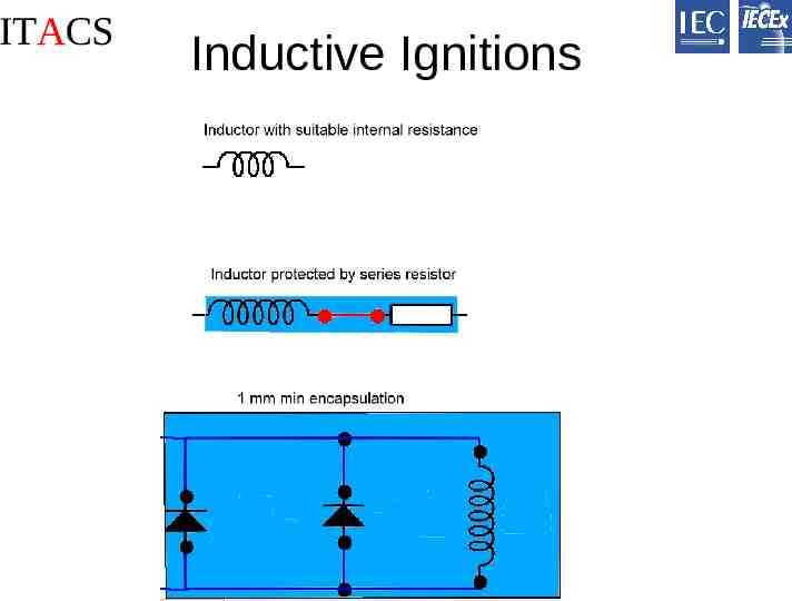
ITACS Inductive Ignitions This approach has the advantage to the designer of the circuit that segregation distances and detailed fault analysis do not have to be applied to the printed wiring board, thus allowing changes to the board without the costly process of reassessing the segregation distances. However, this approach can be very restrictive in the amount of inductance permitted. A solution to this inductive problem is to use the minimum internal resistance of the inductor and the maximum voltage across the inductor to limit the current through the inductor, to an intrinsically safe value. The minimum resistance of the inductor is to be specified in the client’s documentation. The minimum resistance shall be at the lowest ambient temperature that the apparatus may be situated.
ITACS Inductive Ignitions Another common solution to this inductive problem is to use adequately rated and segregated current limiting resistors to limit the current that can flow through high value inductors. These resistor protected inductor networks may then be removed from the cumulative sum of unprotected inductors. The printed wiring board will have to meet the requirements of the Standard for segregation distances for these resistor-protected inductor nodes, but the segregation distances of the remaining circuits may not require checking. A further common solution is to reduce the current that can flow through the inductor by reducing the voltage across the inductor. An infallible voltage clamp can achieve this. Care should also be taken to ensure that under fault conditions these infallible voltage clamps could not be by-passed due to poor segregation.
ITACS Inductive Ignitions A combination of current limiting resistors and infallible voltage clamps can also be used to limit the current through the inductor. A further method of limiting the discharge from an inductor is to encapsulate two shunt connected diodes across the inductor. These components must be rated at two thirds their manufacturers rating. The depth of the encapsulant must not be less than 1 mm. When testing a coil with the spark test apparatus account shall be taken of the increased current in the coil caused by the reduction in its resistance at low temperatures. (Typically -20oC.) When the safety of the inductor is determined from tests using the spark test apparatus full constructional details of the inductor, including details of the core (size and material) if any, will need to be specified in the clients drawings.
ITACS Inductive Ignitions
ITACS Combination of resistive, capacitive and inductive energies IEC 60079.11 clause 10.4.3.2 requires that the effects of the capacitance adding energy to the energy from the power supply through an inductor be considered. The spark test apparatus is often used to proof that the required factor of safety of an equivalent circuit is achieved.
ITACS 2. Assessment reporting and ExTRs Good supporting documentation is essential; – Improves efficiency in verification. – Improves efficiency in variations. – Assists manufacturers in obtaining certification to other schemes
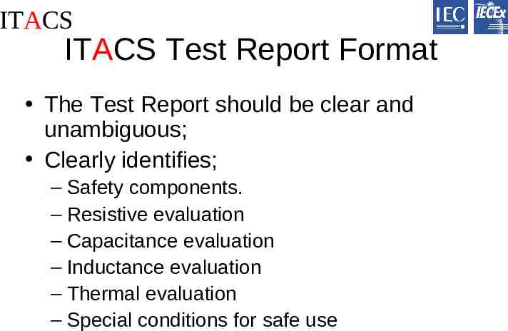
ITACS ITACS Test Report Format The Test Report should be clear and unambiguous; Clearly identifies; – Safety components. – Resistive evaluation – Capacitance evaluation – Inductance evaluation – Thermal evaluation – Special conditions for safe use
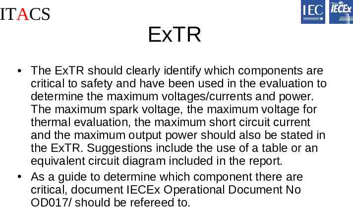
ITACS ExTR The ExTR should clearly identify which components are critical to safety and have been used in the evaluation to determine the maximum voltages/currents and power. The maximum spark voltage, the maximum voltage for thermal evaluation, the maximum short circuit current and the maximum output power should also be stated in the ExTR. Suggestions include the use of a table or an equivalent circuit diagram included in the report. As a guide to determine which component there are critical, document IECEx Operational Document No OD017/ should be refereed to.
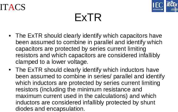
ITACS ExTR The ExTR should clearly identify which capacitors have been assumed to combine in parallel and identify which capacitors are protected by series current limiting resistors and which capacitors are considered infallibly clamped to a lower voltage. The ExTR should clearly identify which inductors have been assumed to combine in series/ parallel and identify which inductors are protected by series current limiting resistors (including the minimum resistance and maximum current used in the calculations) and which inductors are considered infallibly protected by shunt diodes and encapsulation.
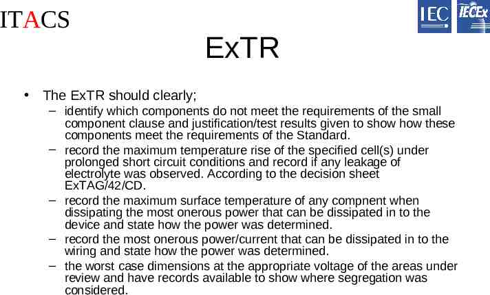
ITACS ExTR The ExTR should clearly; – identify which components do not meet the requirements of the small component clause and justification/test results given to show how these components meet the requirements of the Standard. – record the maximum temperature rise of the specified cell(s) under prolonged short circuit conditions and record if any leakage of electrolyte was observed. According to the decision sheet ExTAG/42/CD. – record the maximum surface temperature of any compnent when dissipating the most onerous power that can be dissipated in to the device and state how the power was determined. – record the most onerous power/current that can be dissipated in to the wiring and state how the power was determined. – the worst case dimensions at the appropriate voltage of the areas under review and have records available to show where segregation was considered.
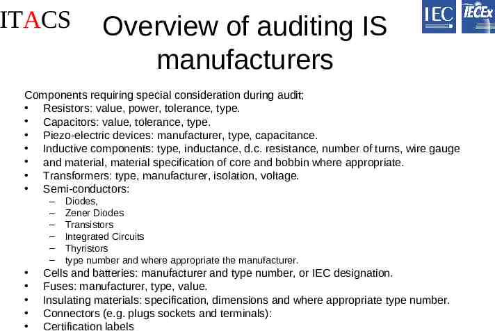
ITACS Overview of auditing IS manufacturers Components requiring special consideration during audit; Resistors: value, power, tolerance, type. Capacitors: value, tolerance, type. Piezo-electric devices: manufacturer, type, capacitance. Inductive components: type, inductance, d.c. resistance, number of turns, wire gauge and material, material specification of core and bobbin where appropriate. Transformers: type, manufacturer, isolation, voltage. Semi-conductors: – – – – – – Diodes, Zener Diodes Transistors Integrated Circuits Thyristors type number and where appropriate the manufacturer. Cells and batteries: manufacturer and type number, or IEC designation. Fuses: manufacturer, type, value. Insulating materials: specification, dimensions and where appropriate type number. Connectors (e.g. plugs sockets and terminals): Certification labels
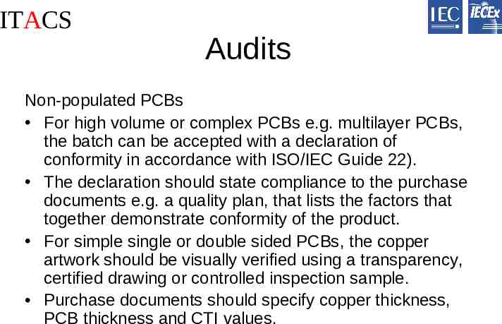
ITACS Audits Non-populated PCBs For high volume or complex PCBs e.g. multilayer PCBs, the batch can be accepted with a declaration of conformity in accordance with ISO/IEC Guide 22). The declaration should state compliance to the purchase documents e.g. a quality plan, that lists the factors that together demonstrate conformity of the product. For simple single or double sided PCBs, the copper artwork should be visually verified using a transparency, certified drawing or controlled inspection sample. Purchase documents should specify copper thickness, PCB thickness and CTI values.
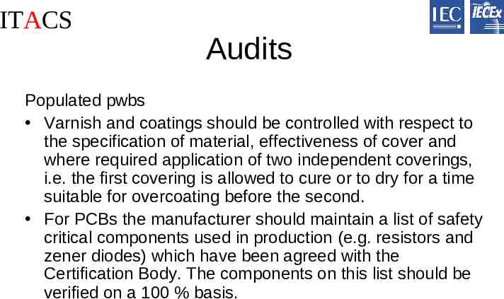
ITACS Audits Populated pwbs Varnish and coatings should be controlled with respect to the specification of material, effectiveness of cover and where required application of two independent coverings, i.e. the first covering is allowed to cure or to dry for a time suitable for overcoating before the second. For PCBs the manufacturer should maintain a list of safety critical components used in production (e.g. resistors and zener diodes) which have been agreed with the Certification Body. The components on this list should be verified on a 100 % basis.
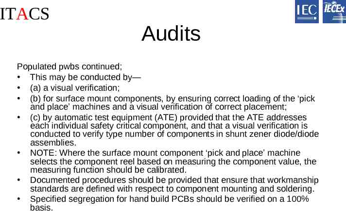
ITACS Audits Populated pwbs continued; This may be conducted by— (a) a visual verification; (b) for surface mount components, by ensuring correct loading of the ‘pick and place’ machines and a visual verification of correct placement; (c) by automatic test equipment (ATE) provided that the ATE addresses each individual safety critical component, and that a visual verification is conducted to verify type number of components in shunt zener diode/diode assemblies. NOTE: Where the surface mount component ‘pick and place’ machine selects the component reel based on measuring the component value, the measuring function should be calibrated. Documented procedures should be provided that ensure that workmanship standards are defined with respect to component mounting and soldering. Specified segregation for hand build PCBs should be verified on a 100% basis.
ITACS Audits Sub-assemblies and assemblies Documented procedures should ensure that production documentation includes all relevant variations to the product design. Production documentation should address all safety critical components, and in the case of encapsulated parts, the encapsulant manufacturer, type, mix and minimum depth. Documented procedures should ensure that segregation of related parts (e.g. terminals) and wiring/cabling is maintained and that specified colours and/or labels are fitted. Sealing arrangements should be verified for compatibility with the product’s ingress protection rating.