Introduction to CAD/CAM


30 Slides987.00 KB
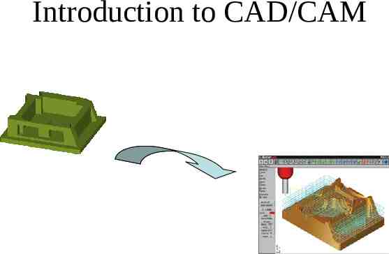
Introduction to CAD/CAM
Agenda Introduction to CAD/CAM Introduction to MASTERCAM 2D CAD using MASTERCAM Tool Path Planning in MASTERCAM Tool Path Optimization
Readings Go through the Tutorial/ MasterCAM Modules on the Web http://130.203.243.91/Lab%20Manuals%20Test%20Site/Frameset.htm Groover Mikell,Zimmers W Emory, CAD/CAM Computer Aided Design and Manufacturing , Chapter 2-5, Prentice Hall 1984. Chang, et al, Computer Aided Manufacturing, Chapter 10, Prentice-Hall, 1991.
Exercise Readiness Assessment Test A.K.A. RAT AS A INDIVIDUAL, INDIVIDUAL prepare a detailed response for the Readiness Assessment test found on the web http://www.engr.psu.edu/cim/ie450/ ie450rat4.doc Open Book / Open Notes
Objectives To understand the need for CAD/CAM in Lean Manufacturing. To be able to create 2D Geometries in MASTERCAM To be able to create 2D toolpaths in MASTERCAM To use MASTERCAM for identifying optimum toolpaths To generate NC codes using MASTERCAM
CAD/CAM Computer-aided design (CAD) is the use of computer systems to assist in the creation, modification, analysis, or optimization of a design. Computer-aided manufacturing (CAM) is the use of computer systems to plan, manage, and control the operations of a manufacturing plant through direct or indirect computer interface with plant’s resources.
Need for CAD/CAM To increase productivity of the designer To improve quality of the design To improve communications To create a manufacturing database To create and test toolpaths and optimize them To help in production scheduling and MRP models To have effective shop floor control
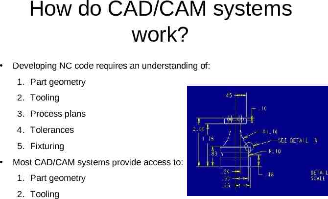
How do CAD/CAM systems work? Developing NC code requires an understanding of: 1. Part geometry 2. Tooling 3. Process plans 4. Tolerances 5. Fixturing Most CAD/CAM systems provide access to: 1. Part geometry 2. Tooling
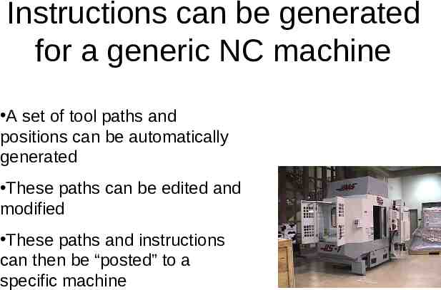
Instructions can be generated for a generic NC machine A set of tool paths and positions can be automatically generated These paths can be edited and modified These paths and instructions can then be “posted” to a specific machine
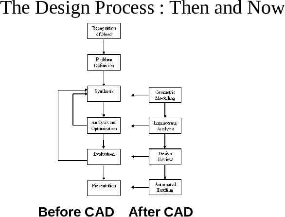
The Design Process : Then and Now Before CAD After CAD
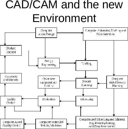
CAD/CAM and the new Environment
Exercise (3-5 mins) Discuss how CAD/CAM helps in Lean Manufacturing? Elaborate on any one aspect. What advantages does CAD/CAM approach offer in NC Programming?
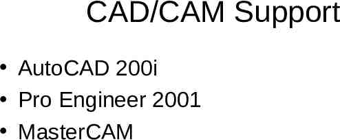
CAD/CAM Support AutoCAD 200i Pro Engineer 2001 MasterCAM
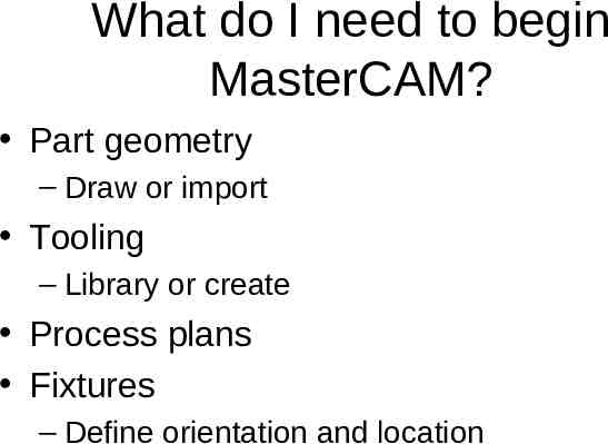
What do I need to begin MasterCAM? Part geometry – Draw or import Tooling – Library or create Process plans Fixtures – Define orientation and location
MasterCAM Mastercam is a three-dimensional geometry creation engine along with features to aid in tool path generation and verification. MasterCAM allows tool path planning and NC code generation for a given part. This part can either be drawn in MasterCAM or imported from other CAD packages
MasterCAM Drawing Geometrical part drawing – In-built CAD package Two-dimensional parts Three-dimensional parts – Translators (include) IGES (international Graphics Exchange Standard) DXF (AutoCad) CADL (CADKey)
Tool Path Generation using MasterCAM Tool path generation – Extensive Tool library – Machining parameter selection – NC program generator – Animation to visualize machining operations
Exercise (individual) Is it always good to use a CAD/CAM package? Why? What are the advantages of using a CAD/CAM system?
Exercise (Group) Develop a set of rules as to when to use a CAD/CAM system. Create an economic model that can be used to justify using MasterCAM or a similar system.
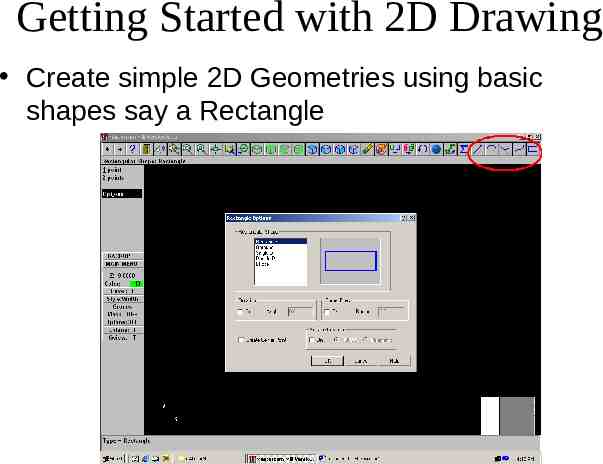
Getting Started with 2D Drawing Create simple 2D Geometries using basic shapes say a Rectangle
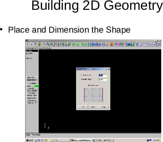
Building 2D Geometry Place and Dimension the Shape
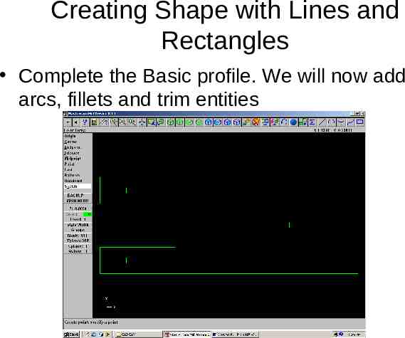
Creating Shape with Lines and Rectangles Complete the Basic profile. We will now add arcs, fillets and trim entities
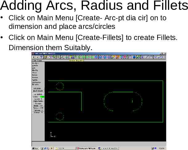
Adding Arcs, Radius and Fillets Click on Main Menu [Create- Arc-pt dia cir] on to dimension and place arcs/circles Click on Main Menu [Create-Fillets] to create Fillets. Dimension them Suitably.
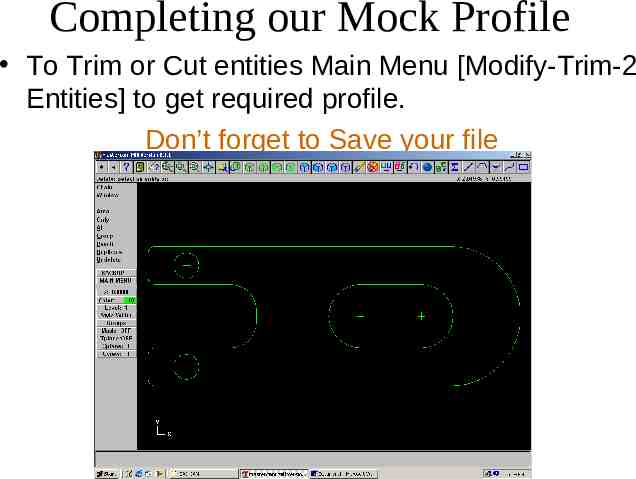
Completing our Mock Profile To Trim or Cut entities Main Menu [Modify-Trim-2 Entities] to get required profile. Don’t forget to Save your file
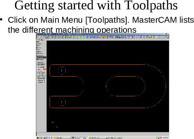
Getting started with Toolpaths Click on Main Menu [Toolpaths]. MasterCAM lists the different machining operations
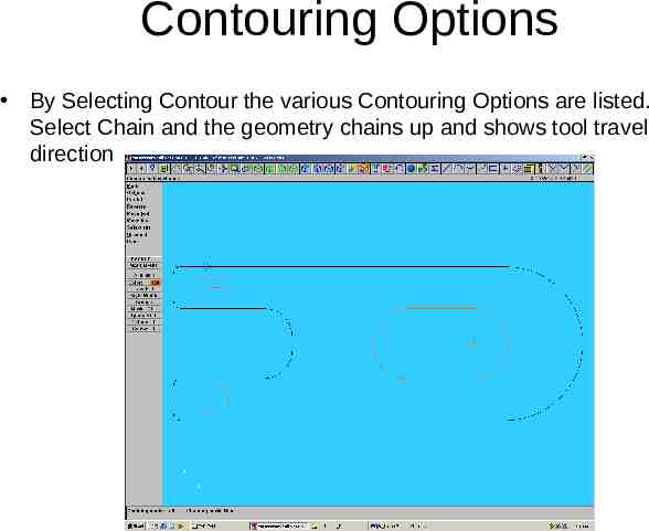
Contouring Options By Selecting Contour the various Contouring Options are listed. Select Chain and the geometry chains up and shows tool travel direction
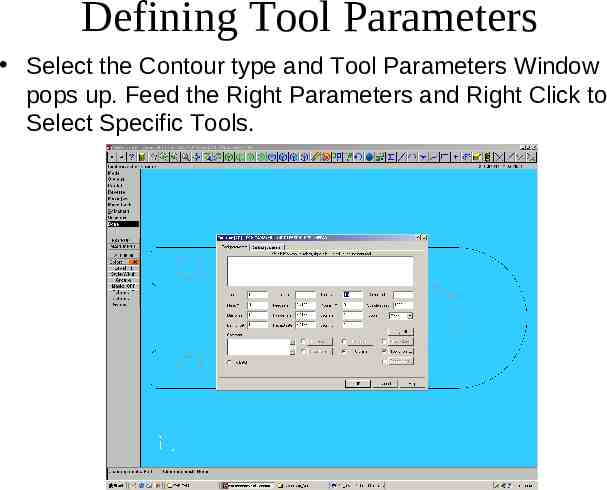
Defining Tool Parameters Select the Contour type and Tool Parameters Window pops up. Feed the Right Parameters and Right Click to Select Specific Tools.
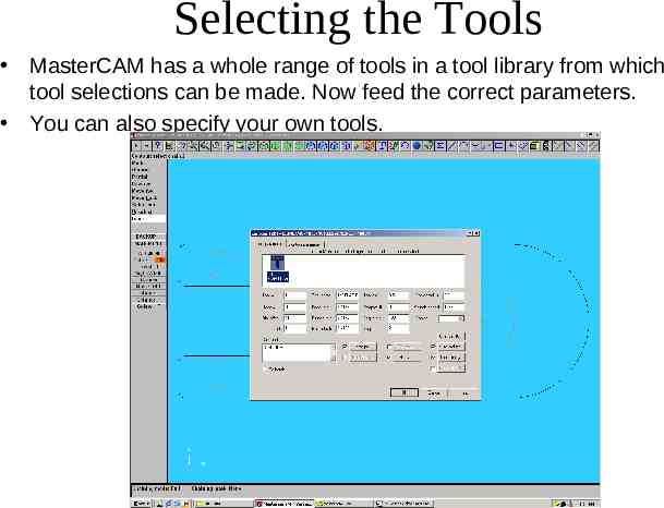
Selecting the Tools MasterCAM has a whole range of tools in a tool library from which tool selections can be made. Now feed the correct parameters. You can also specify your own tools.
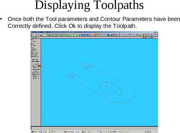
Displaying Toolpaths Once both the Tool parameters and Contour Parameters have been Correctly defined. Click Ok to display the Toolpath.
Toolpath Optimization? MASTERCAM does NOT give a minimum time Toolpath. It gives the toolpath that has been selected. Exercise : Try out different toolpaths from the toolpaths pallete for the part in the tutorial. Which one is optimal? Why?