IELM 511: Information System design Introduction Part 1. ISD for well


29 Slides2.32 MB
IELM 511: Information System design Introduction Part 1. ISD for well structured data – relational and other DBMS Info storage (modeling, normalization) Info retrieval (Relational algebra, Calculus, SQL) DB integrated API’s ISD for systems with non-uniformly structured data Basics of web-based IS (www, web2.0, ) Markup’s, HTML, XML Design tools for Info Sys: UML Part III: (one out of) API’s for mobile apps Security, Cryptography IS product lifecycles Algorithm analysis, P, NP, NPC
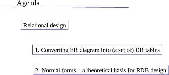
Agenda Relational design 1. Converting ER diagram into (a set of) DB tables 2. Normal forms – a theoretical basis for RDB design
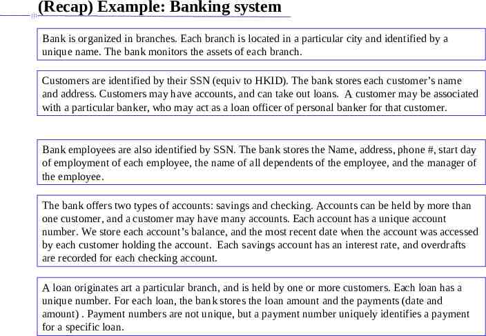
(Recap) Example: Banking system Bank is organized in branches. Each branch is located in a particular city and identified by a unique name. The bank monitors the assets of each branch. Customers are identified by their SSN (equiv to HKID). The bank stores each customer’s name and address. Customers may have accounts, and can take out loans. A customer may be associated with a particular banker, who may act as a loan officer of personal banker for that customer. Bank employees are also identified by SSN. The bank stores the Name, address, phone #, start day of employment of each employee, the name of all dependents of the employee, and the manager of the employee. The bank offers two types of accounts: savings and checking. Accounts can be held by more than one customer, and a customer may have many accounts. Each account has a unique account number. We store each account’s balance, and the most recent date when the account was accessed by each customer holding the account. Each savings account has an interest rate, and overdrafts are recorded for each checking account. A loan originates art a particular branch, and is held by one or more customers. Each loan has a unique number. For each loan, the bank stores the loan amount and the payments (date and amount) . Payment numbers are not unique, but a payment number uniquely identifies a payment for a specific loan.
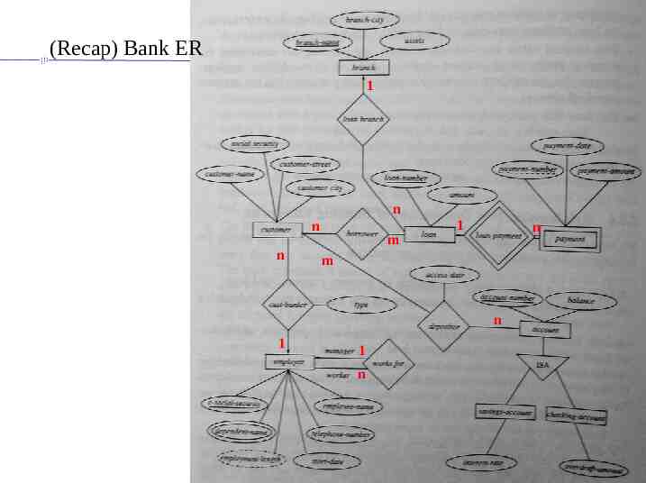
(Recap) Bank ER 1 n n n m 1 n m n 1 1 n
Agenda Relational design 1. Converting ER diagram into (a set of) DB tables 2. Normal forms – a theoretical basis for RDB design
Converting ER into Relational tables: rationale There is an informal set of rules to convert ER diagrams into Tables This is a very good initial design for most DB’s Normalization can be used to verify/improve this initial design
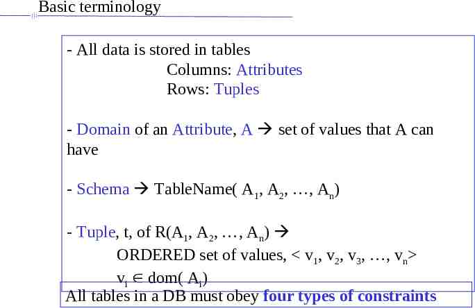
Basic terminology - All data is stored in tables Columns: Attributes Rows: Tuples - Domain of an Attribute, A set of values that A can have - Schema TableName( A1, A2, , An) - Tuple, t, of R(A1, A2, , An) ORDERED set of values, v1, v2, v3, , vn vi dom( Ai) All tables in a DB must obey four types of constraints
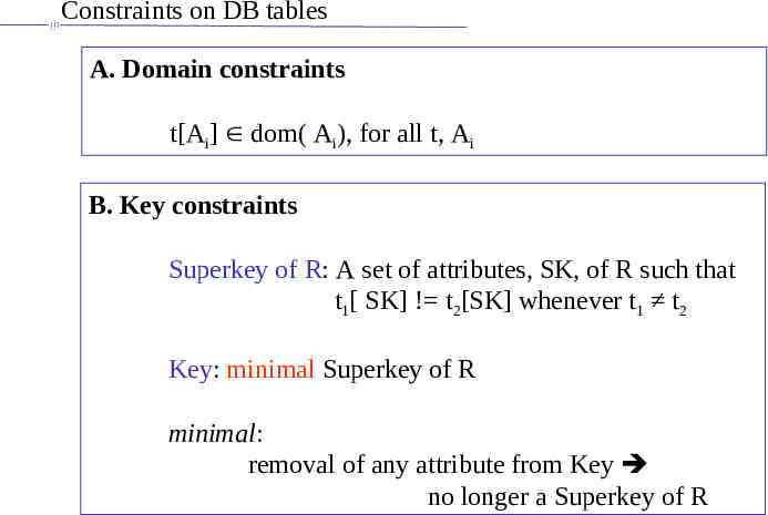
Constraints on DB tables A. Domain constraints t[Ai] dom( Ai), for all t, Ai B. Key constraints Superkey of R: A set of attributes, SK, of R such that t1[ SK] ! t2[SK] whenever t1 t2 Key: minimal Superkey of R minimal: removal of any attribute from Key no longer a Superkey of R
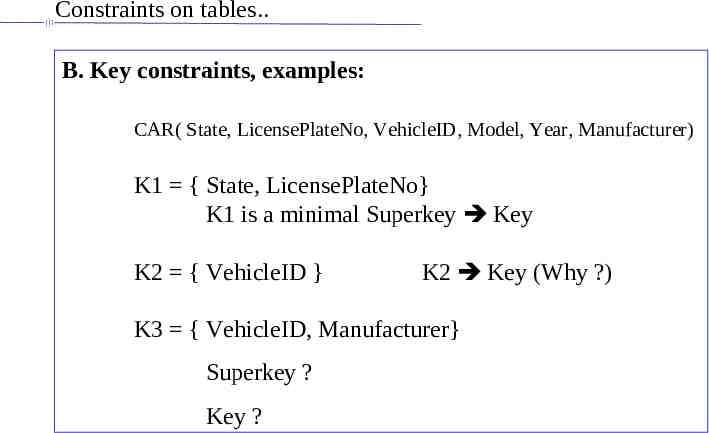
Constraints on tables. B. Key constraints, examples: CAR( State, LicensePlateNo, VehicleID, Model, Year, Manufacturer) K1 { State, LicensePlateNo} K1 is a minimal Superkey Key K2 { VehicleID } K2 Key (Why ?) K3 { VehicleID, Manufacturer} Superkey ? Key ?
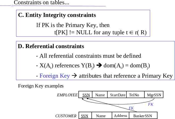
Constraints on tables. C. Entity Integrity constraints If PK is the Primary Key, then t[PK] ! NULL for any tuple t r( R) D. Referential constraints - All referential constraints must be defined - X(Ai) references Y(Bj) dom(Ai) dom(Bj) - Foreign Key attributes that reference a Primary Key Foreign Key examples EMPLOYEE SSN Name StartDate TelNo FK CUSTOMER SSN Name Address MgrSSN FK BankerSSN
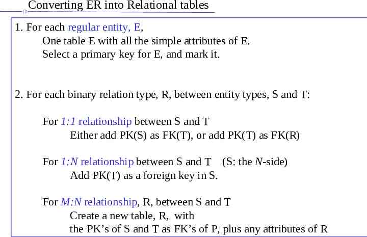
Converting ER into Relational tables 1. For each regular entity, E, One table E with all the simple attributes of E. Select a primary key for E, and mark it. 2. For each binary relation type, R, between entity types, S and T: For 1:1 relationship between S and T Either add PK(S) as FK(T), or add PK(T) as FK(R) For 1:N relationship between S and T (S: the N-side) Add PK(T) as a foreign key in S. For M:N relationship, R, between S and T Create a new table, R, with the PK’s of S and T as FK’s of P, plus any attributes of R
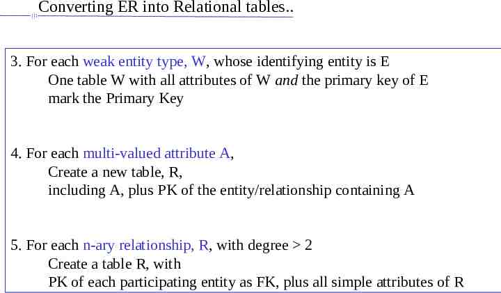
Converting ER into Relational tables. 3. For each weak entity type, W, whose identifying entity is E One table W with all attributes of W and the primary key of E mark the Primary Key 4. For each multi-valued attribute A, Create a new table, R, including A, plus PK of the entity/relationship containing A 5. For each n-ary relationship, R, with degree 2 Create a table R, with PK of each participating entity as FK, plus all simple attributes of R
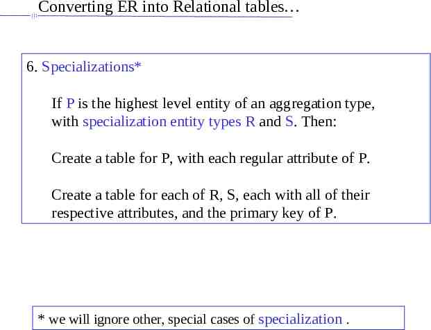
Converting ER into Relational tables 6. Specializations* If P is the highest level entity of an aggregation type, with specialization entity types R and S. Then: Create a table for P, with each regular attribute of P. Create a table for each of R, S, each with all of their respective attributes, and the primary key of P. * we will ignore other, special cases of specialization .
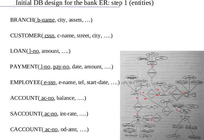
Initial DB design for the bank ER: step 1 (entities) BRANCH( b-name, city, assets, ) CUSTOMER( cssn, c-name, street, city, .) LOAN( l-no, amount, .) PAYMENT( l-no, pay-no, date, amount, .) 1 EMPLOYEE( e-ssn, e-name, tel, start-date, .) n n ACCOUNT( ac-no, balance, .) SACCOUNT( ac-no, int-rate, .) n m n m n 1 1 n CACCOUNT( ac-no, od-amt, .) 1
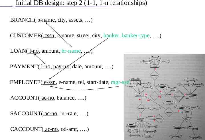
Initial DB design: step 2 (1-1, 1-n relationships) BRANCH( b-name, city, assets, ) CUSTOMER( cssn, c-name, street, city, banker, banker-type, .) LOAN( l-no, amount, br-name, .) PAYMENT( l-no, pay-no, date, amount, .) 1 EMPLOYEE( e-ssn, e-name, tel, start-date, mgr-ssn, .) n ACCOUNT( ac-no, balance, .) SACCOUNT( ac-no, int-rate, .) n n m n m n 1 1 n CACCOUNT( ac-no, od-amt, .) 1
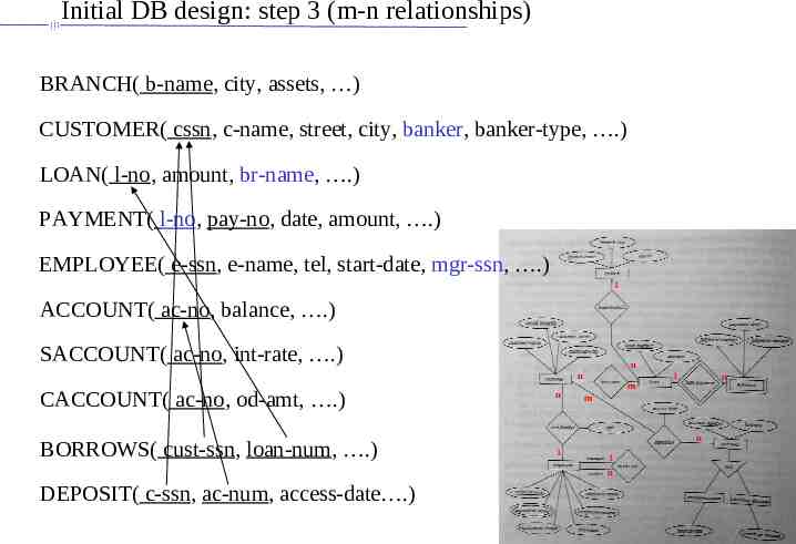
Initial DB design: step 3 (m-n relationships) BRANCH( b-name, city, assets, ) CUSTOMER( cssn, c-name, street, city, banker, banker-type, .) LOAN( l-no, amount, br-name, .) PAYMENT( l-no, pay-no, date, amount, .) EMPLOYEE( e-ssn, e-name, tel, start-date, mgr-ssn, .) 1 ACCOUNT( ac-no, balance, .) SACCOUNT( ac-no, int-rate, .) n n CACCOUNT( ac-no, od-amt, .) BORROWS( cust-ssn, loan-num, .) n m n m n 1 1 n DEPOSIT( c-ssn, ac-num, access-date .) 1
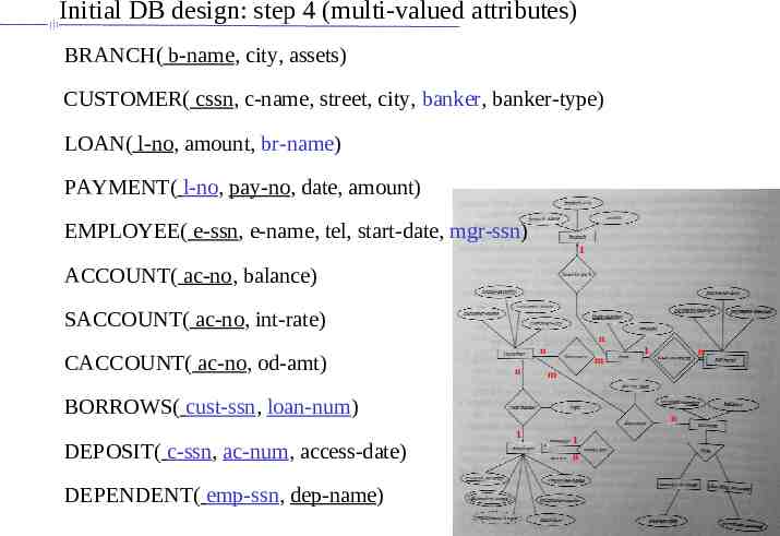
Initial DB design: step 4 (multi-valued attributes) BRANCH( b-name, city, assets) CUSTOMER( cssn, c-name, street, city, banker, banker-type) LOAN( l-no, amount, br-name) PAYMENT( l-no, pay-no, date, amount) EMPLOYEE( e-ssn, e-name, tel, start-date, mgr-ssn) 1 ACCOUNT( ac-no, balance) SACCOUNT( ac-no, int-rate) n CACCOUNT( ac-no, od-amt) n n m DEPENDENT( emp-ssn, dep-name) n m BORROWS( cust-ssn, loan-num) DEPOSIT( c-ssn, ac-num, access-date) 1 n 1 1 n
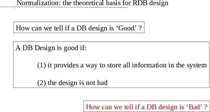
Normalization: the theoretical basis for RDB design How can we tell if a DB design is ‘Good’ ? A DB Design is good if: (1) it provides a way to store all information in the system (2) the design is not bad How can we tell if a DB design is ‘Bad’ ?
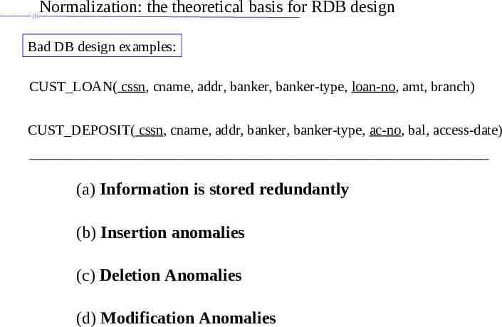
Normalization: the theoretical basis for RDB design Bad DB design examples: CUST LOAN( cssn, cname, addr, banker, banker-type, loan-no, amt, branch) CUST DEPOSIT( cssn, cname, addr, banker, banker-type, ac-no, bal, access-date) (a) Information is stored redundantly (b) Insertion anomalies (c) Deletion Anomalies (d) Modification Anomalies
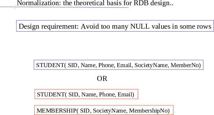
Normalization: the theoretical basis for RDB design. Design requirement: Avoid too many NULL values in some rows STUDENT( SID, Name, Phone, Email, SocietyName, MemberNo) OR STUDENT( SID, Name, Phone, Email) MEMBERSHIP( SID, SocietyName, MembershipNo)
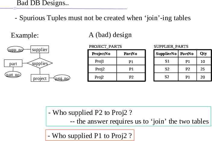
Bad DB Designs. - Spurious Tuples must not be created when ‘join’-ing tables A (bad) design Example: supp no part part no PROJECT PARTS supplier ProjectNo supplies project proj no SUPPLIER PARTS PartNo SupplierNo PartNo Qty Proj1 P1 S1 P1 10 Proj2 P1 S2 P2 25 Proj2 P2 S2 P1 20 - Who supplied P2 to Proj2 ? -- the answer requires us to ‘join’ the two tables - Who supplied P1 to Proj2 ?
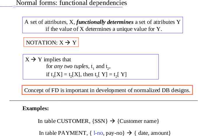
Normal forms: functional dependencies A set of attributes, X, functionally determines a set of attributes Y if the value of X determines a unique value for Y. NOTATION: X Y X Y implies that for any two tuples, t1 and t2, if t1[X] t2[X], then t1[ Y] t2[ Y] Concept of FD is important in development of normalized DB designs. Examples: In table CUSTOMER, {SSN} {Customer name} In table PAYMENT, { l-no, pay-no} { date, amount}
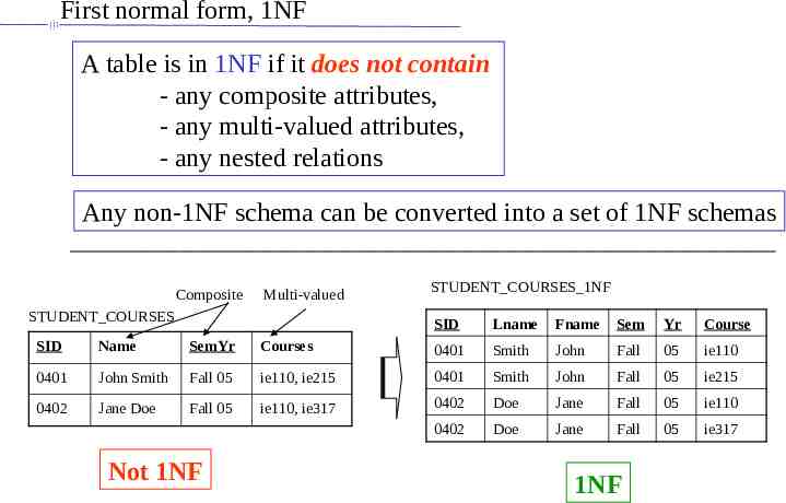
First normal form, 1NF A table is in 1NF if it does not contain - any composite attributes, - any multi-valued attributes, - any nested relations Any non-1NF schema can be converted into a set of 1NF schemas Composite Multi-valued STUDENT COURSES STUDENT COURSES 1NF SID Lname Fname Sem Yr Course SID Name SemYr Courses 0401 Smith John Fall 05 ie110 0401 John Smith Fall 05 ie110, ie215 0401 Smith John Fall 05 ie215 0402 Jane Doe Fall 05 ie110, ie317 0402 Doe Jane Fall 05 ie110 0402 Doe Jane Fall 05 ie317 Not 1NF 1NF
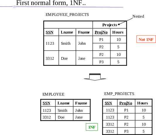
First normal form, 1NF. EMPLOYEE PROJECTS Nested Projects SSN Lname Fname 1123 Smith John 3312 Doe ProjNo Hours P1 10 P2 5 P2 10 P3 5 Jane Not 1NF EMP PROJECTS EMPLOYEE SSN Lname Fname 1123 Smith John 3312 Doe Jane SSN 1NF ProjNo Hours 1123 P1 10 1123 P2 5 3312 P2 10 3312 P3 5
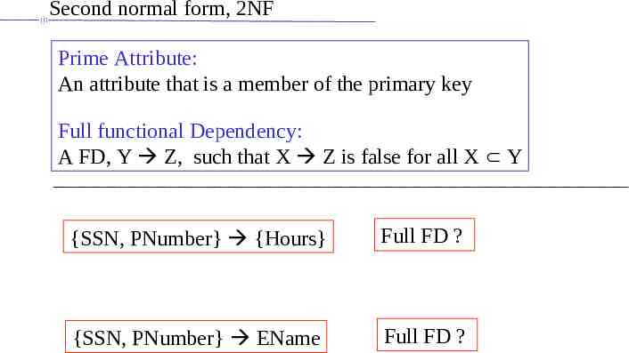
Second normal form, 2NF Prime Attribute: An attribute that is a member of the primary key Full functional Dependency: A FD, Y Z, such that X Z is false for all X Y {SSN, PNumber} {Hours} Full FD ? {SSN, PNumber} EName Full FD ?
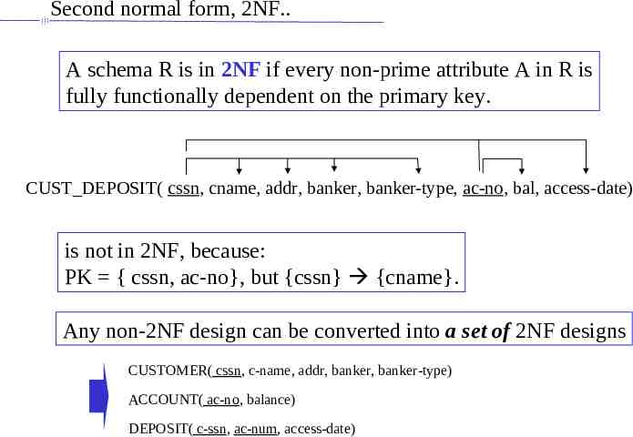
Second normal form, 2NF. A schema R is in 2NF if every non-prime attribute A in R is fully functionally dependent on the primary key. CUST DEPOSIT( cssn, cname, addr, banker, banker-type, ac-no, bal, access-date) is not in 2NF, because: PK { cssn, ac-no}, but {cssn} {cname}. Any non-2NF design can be converted into a set of 2NF designs CUSTOMER( cssn, c-name, addr, banker, banker-type) ACCOUNT( ac-no, balance) DEPOSIT( c-ssn, ac-num, access-date)
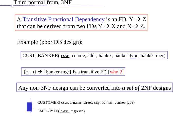
Third normal from, 3NF A Transitive Functional Dependency is an FD, Y Z that can be derived from two FDs Y X and X Z. Example (poor DB design): CUST BANKER( cssn, cname, addr, banker, banker-type, banker-mgr) {cssn} {banker-mgr} is a transitive FD [why ?] Any non-3NF design can be converted into a set of 2NF designs CUSTOMER( cssn, c-name, street, city, banker, banker-type) EMPLOYEE( e-ssn, mgr-ssn)
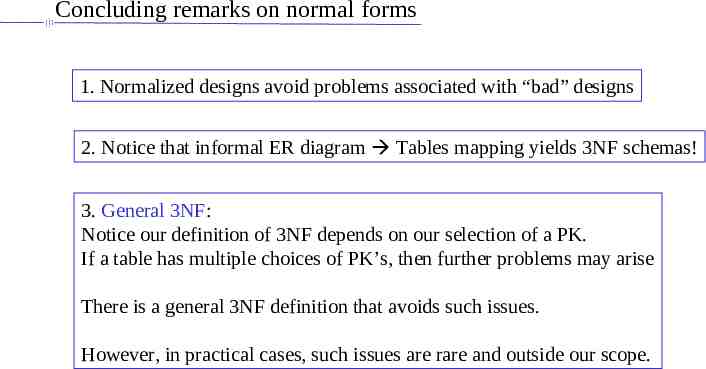
Concluding remarks on normal forms 1. Normalized designs avoid problems associated with “bad” designs 2. Notice that informal ER diagram Tables mapping yields 3NF schemas! 3. General 3NF: Notice our definition of 3NF depends on our selection of a PK. If a table has multiple choices of PK’s, then further problems may arise There is a general 3NF definition that avoids such issues. However, in practical cases, such issues are rare and outside our scope.
References and Further Reading Silberschatz, Korth, Sudarshan, Database Systems Concepts, McGraw Hill Next: Relational algebra, calculus, and SQL