SYEN 3330 Digital Systems Chapter 7 – Part 3 SYEN 3330 Digital Systems
23 Slides144.00 KB
SYEN 3330 Digital Systems Chapter 7 – Part 3 SYEN 3330 Digital Systems Jung H. Kim 1
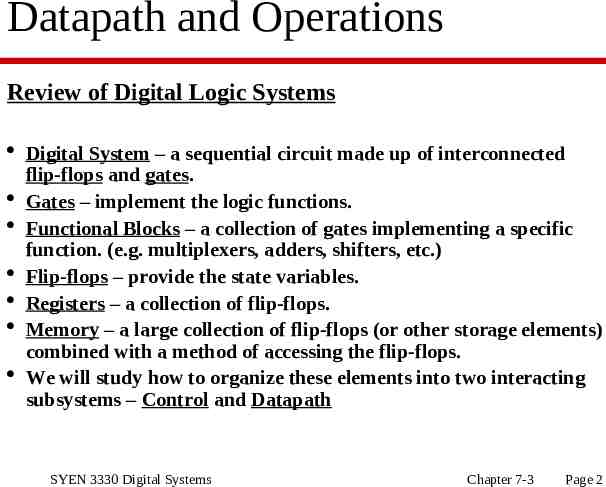
Datapath and Operations Review of Digital Logic Systems Digital System – a sequential circuit made up of interconnected flip-flops and gates. Gates – implement the logic functions. Functional Blocks – a collection of gates implementing a specific function. (e.g. multiplexers, adders, shifters, etc.) Flip-flops – provide the state variables. Registers – a collection of flip-flops. Memory – a large collection of flip-flops (or other storage elements) combined with a method of accessing the flip-flops. We will study how to organize these elements into two interacting subsystems – Control and Datapath SYEN 3330 Digital Systems Chapter 7-3 Page 2
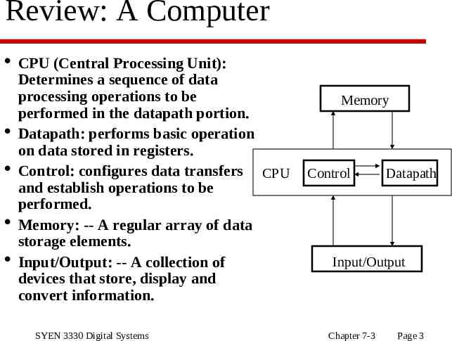
Review: A Computer CPU (Central Processing Unit): Determines a sequence of data processing operations to be performed in the datapath portion. Datapath: performs basic operation on data stored in registers. Control: configures data transfers CPU and establish operations to be performed. Memory: -- A regular array of data storage elements. Input/Output: -- A collection of devices that store, display and convert information. SYEN 3330 Digital Systems Memory Control Datapath Input/Output Chapter 7-3 Page 3
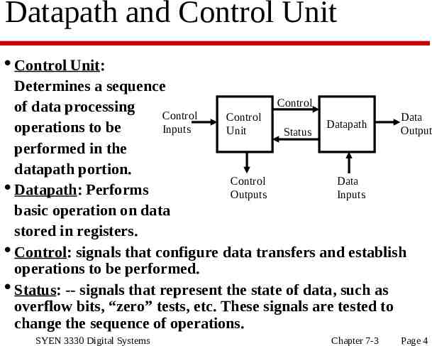
Datapath and Control Unit Control Unit: Determines a sequence Control of data processing Control Control Data Datapath operations to be Inputs Unit Output Status performed in the datapath portion. Control Data Datapath: Performs Outputs Inputs basic operation on data stored in registers. Control: signals that configure data transfers and establish operations to be performed. Status: -- signals that represent the state of data, such as overflow bits, “zero” tests, etc. These signals are tested to change the sequence of operations. SYEN 3330 Digital Systems Chapter 7-3 Page 4
Register Transfer Operations Resisters – a collection of binary storage flip-flops organized in some logical fashion. Register Transfer Operations – the movement of data stored in registers and the processing performed on the data. Three basic components: Set of registers Operations Control Elementary Operations Load, count, shift, add, bitwise “OR”, etc. Elementary operations are called micro-operations. SYEN 3330 Digital Systems Chapter 7-3 Page 5
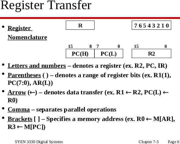
Register Transfer R Register Nomenclature 15 PC(H) 76543210 8 7 0 PC(L) 15 0 R2 Letters and numbers – denotes a register (ex. R2, PC, IR) Parentheses ( ) – denotes a range of register bits (ex. R1(1), PC(7:0), AR(L)) Arrow ( ) – denotes data transfer (ex. R1 R2, PC(L) R0) Comma – separates parallel operations Brackets [ ] – Specifies a memory address (ex. R0 M[AR], R3 M[PC]) SYEN 3330 Digital Systems Chapter 7-3 Page 6
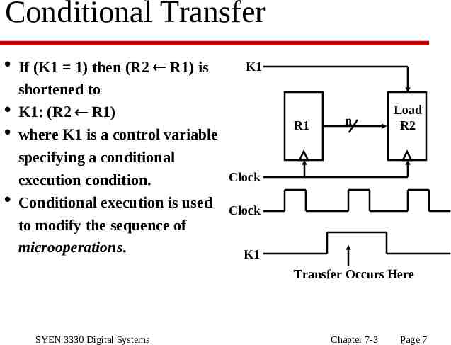
Conditional Transfer If (K1 1) then (R2 R1) is K1 shortened to K1: (R2 R1) where K1 is a control variable specifying a conditional Clock execution condition. Conditional execution is used Clock to modify the sequence of microoperations. K1 R1 n Load R2 Transfer Occurs Here SYEN 3330 Digital Systems Chapter 7-3 Page 7
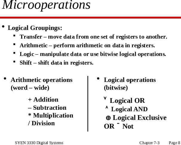
Microoperations Logical Groupings: Transfer – move data from one set of registers to another. Arithmetic – perform arithmetic on data in registers. Logic – manipulate data or use bitwise logical operations. Shift – shift data in registers. Arithmetic operations (word – wide) Addition – Subtraction * Multiplication / Division SYEN 3330 Digital Systems Logical operations (bitwise) Logical OR Logical AND Logical Exclusive OR Not Chapter 7-3 Page 8
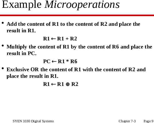
Example Microoperations Add the content of R1 to the content of R2 and place the result in R1. R1 R1 R2 Multiply the content of R1 by the content of R6 and place the result in PC. PC R1 * R6 Exclusive OR the content of R1 with the content of R2 and place the result in R1. R1 R1 R2 SYEN 3330 Digital Systems Chapter 7-3 Page 9
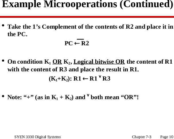
Example Microoperations (Continued) Take the 1’s Complement of the contents of R2 and place it in the PC. PC R2 On condition K1 OR K2, Logical bitwise OR the content of R1 with the content of R3 and place the result in R1. (K1 K2): R1 R1 R3 Note: “ ” (as in K1 K2) and both mean “OR”! SYEN 3330 Digital Systems Chapter 7-3 Page 10
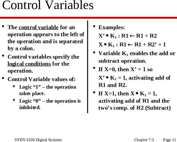
Control Variables The control variable for an operation appears to the left of the operation and is separated by a colon. Control variables specify the logical conditions for the operation. Control Variable values of: Logic “1” – the operation takes place. Logic “0” – the operation is inhibited. SYEN 3330 Digital Systems Examples: X’ K1 : R1 R1 R2 X K1 : R1 R1 R2’ 1 Variable K1 enables the add or subtract operation. If X 0, then X’ 1 so X’ K1 1, activating add of R1 and R2. If X 1, then X K1 1, activating add of R1 and the two’s comp. of R2 (Subtract) Chapter 7-3 Page 11
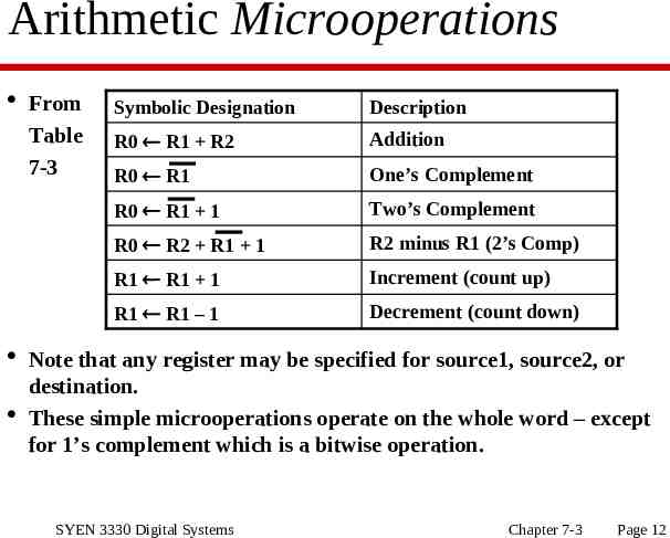
Arithmetic Microoperations From Table 7-3 Symbolic Designation Description R0 R1 R2 Addition R0 R1 One’s Complement R0 R1 1 Two’s Complement R0 R2 R1 1 R2 minus R1 (2’s Comp) R1 R1 1 Increment (count up) R1 R1 – 1 Decrement (count down) Note that any register may be specified for source1, source2, or destination. These simple microoperations operate on the whole word – except for 1’s complement which is a bitwise operation. SYEN 3330 Digital Systems Chapter 7-3 Page 12
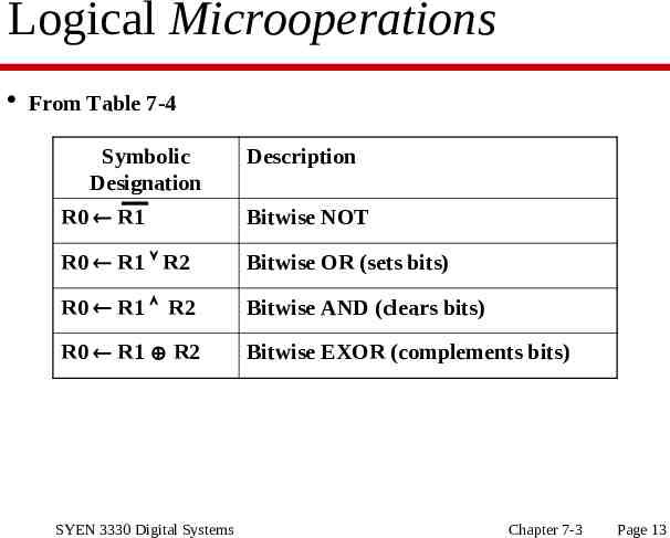
Logical Microoperations From Table 7-4 Symbolic Designation Description R0 R1 Bitwise NOT R0 R1 R2 Bitwise OR (sets bits) R0 R1 R2 Bitwise AND (clears bits) R0 R1 R2 Bitwise EXOR (complements bits) SYEN 3330 Digital Systems Chapter 7-3 Page 13
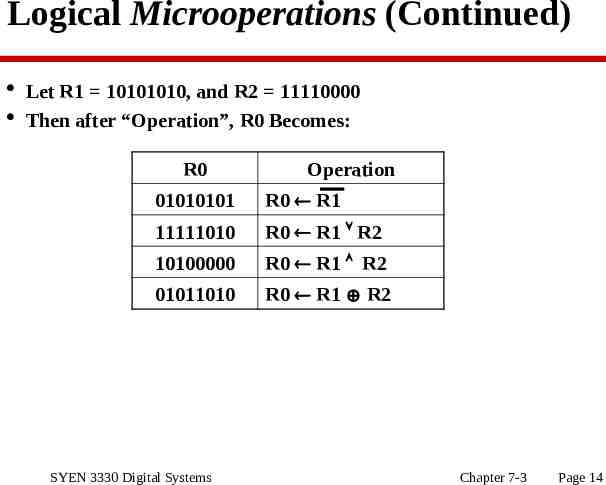
Logical Microoperations (Continued) Let R1 10101010, and R2 11110000 Then after “Operation”, R0 Becomes: R0 Operation 01010101 R0 R1 11111010 R0 R1 R2 10100000 R0 R1 R2 01011010 R0 R1 R2 SYEN 3330 Digital Systems Chapter 7-3 Page 14
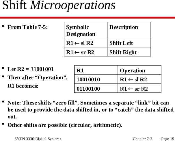
Shift Microoperations From Table 7-5: Symbolic Designation Description R1 sl R2 Shift Left R1 sr R2 Shift Right Let R2 11001001 Then after “Operation”, R1 becomes: R1 Operation 10010010 R1 sl R2 01100100 R1 sr R2 Note: These shifts “zero fill”. Sometimes a separate “link” bit can be used to provide the data shifted in, or to “catch” the data shifted out. Other shifts are possible (circular, arithmetic). SYEN 3330 Digital Systems Chapter 7-3 Page 15
Register Transfer Structures Multiplexer-Based Transfers Register inputs are connected to multiple sources via a multiplexer. Bus-Based Transfers Register inputs are connected to a single bus driven by a multiplexer. Three-State Bus Register inputs and outputs are connected to a single bus via tri-state drivers. Memory Transfer Registers provide a source for Memory Addresses and a source or sink for Memory Data. Other Transfer Structure Use multiple multiplexers, multiple busses, combinations of all the above, etc. SYEN 3330 Digital Systems Chapter 7-3 Page 16
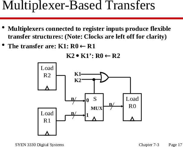
Multiplexer-Based Transfers Multiplexers connected to register inputs produce flexible transfer structures: (Note: Clocks are left off for clarity) The transfer are: K1: R0 R1 K2 K1’: R0 R2 Load R2 K1 K2 n Load R1 SYEN 3330 Digital Systems n 0 S MUX n Load R0 1 Chapter 7-3 Page 17
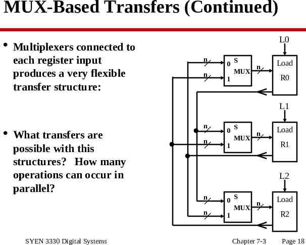
MUX-Based Transfers (Continued) L0 Multiplexers connected to each register input produces a very flexible transfer structure: n n 0 S n MUX 1 Load R0 L1 What transfers are possible with this structures? How many operations can occur in parallel? n n 1 S MUX n Load R1 L2 n n SYEN 3330 Digital Systems 0 0 S n MUX 1 Chapter 7-3 Load R2 Page 18
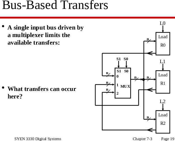
Bus-Based Transfers L0 A single input bus driven by a multiplexer limits the available transfers: n R0 S1 S0 n n What transfers can occur here? Load n S1 S0 0 1 MUX L1 n n Load R1 2 L2 n Load R2 SYEN 3330 Digital Systems Chapter 7-3 Page 19
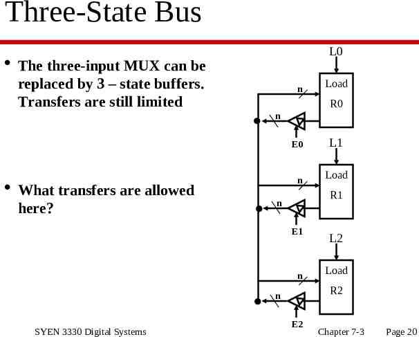
Three-State Bus L0 The three-input MUX can be replaced by 3 – state buffers. Transfers are still limited n R0 n E0 What transfers are allowed here? n n L1 Load R1 n E1 SYEN 3330 Digital Systems Load L2 Load R2 n E2 Chapter 7-3 Page 20
Memory Transfer Memory operations require: ADDRESS And require DATA (write operations), Or provide DATA (read operations) Typically: There can be more than one memory address source in a system There can be more than one data source or data sink in a system Some structure of busses and multiplexers is needed to access the memory. SYEN 3330 Digital Systems Chapter 7-3 Page 21
Other Transfer Structures Fast systems require that parallel operations occur within the same clock. Parallel operations imply “resources” required to move the data SO: Multiple busses are used, and Multiplexers are used to select input sources. THIS REQUIRES MOER HARDWARE! SYEN 3330 Digital Systems Chapter 7-3 Page 22
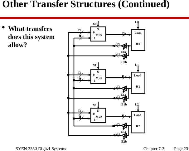
Other Transfer Structures (Continued) What transfers does this system allow? L0 S0 n n 0 1 S n MUX n Load R0 n E0a E0b S1 n n 0 1 S n MUX n L1 Load R1 n E1a S2 n n 0 1 E1b L2 n Load S MUX n R2 n E2a E2b SYEN 3330 Digital Systems Chapter 7-3 Page 23