How the TCP/IP Protocol Works Les Cottrell – SLAC Lecture

49 Slides465.00 KB
How the TCP/IP Protocol Works Les Cottrell – SLAC Lecture # 1 presented at the 26th International Nathiagali Summer College on Physics and Contemporary Needs, 25th June – 14th July, Nathiagali, Pakistan Partially funded by DOE/MICS Field Work Proposal on Internet End-to-end Performance Monitoring (IEPM), also supported by IUPAP 1
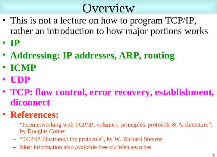
Overview This is not a lecture on how to program TCP/IP, rather an introduction to how major portions works IP Addressing: IP addresses, ARP, routing ICMP UDP TCP: flow control, error recovery, establishment, diconnect References: – “Internetworking with TCP/IP, volume I, principles, protocols & Architecture”, by Douglas Comer – “TCP/IP Illustrated: the protocols”, by W. Richard Stevens – Most information also available free via Web searches 2
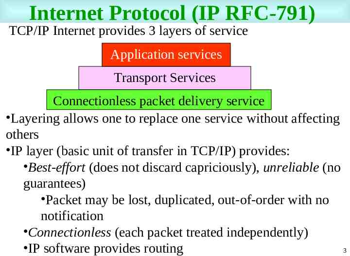
Internet Protocol (IP RFC-791) TCP/IP Internet provides 3 layers of service Application services Transport Services Connectionless packet delivery service Layering allows one to replace one service without affecting others IP layer (basic unit of transfer in TCP/IP) provides: Best-effort (does not discard capriciously), unreliable (no guarantees) Packet may be lost, duplicated, out-of-order with no notification Connectionless (each packet treated independently) IP software provides routing 3
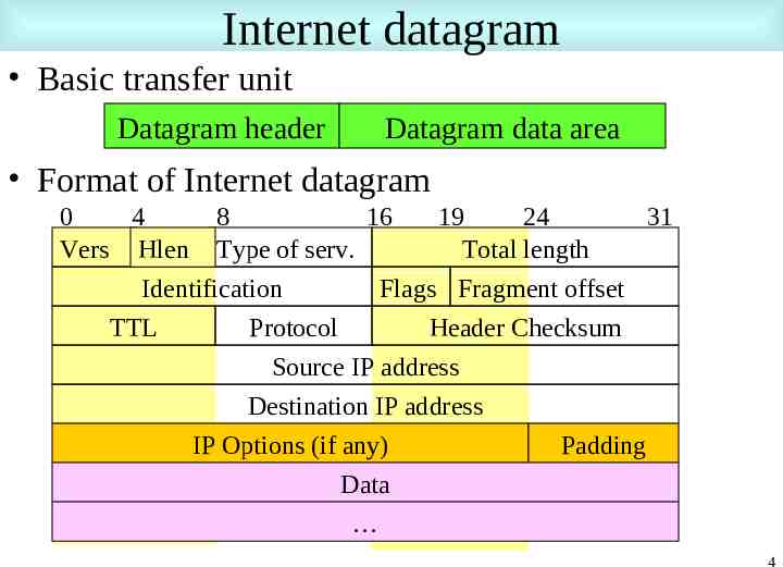
Internet datagram Basic transfer unit Datagram header Datagram data area Format of Internet datagram 0 4 8 16 19 24 31 Vers Hlen Type of serv. Total length Identification Flags Fragment offset TTL Protocol Header Checksum Source IP address Destination IP address IP Options (if any) Padding Data 4
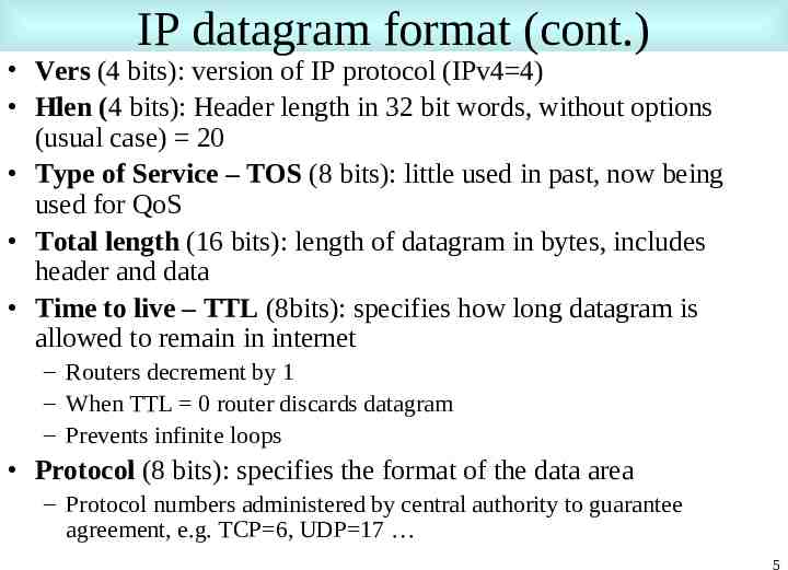
IP datagram format (cont.) Vers (4 bits): version of IP protocol (IPv4 4) Hlen (4 bits): Header length in 32 bit words, without options (usual case) 20 Type of Service – TOS (8 bits): little used in past, now being used for QoS Total length (16 bits): length of datagram in bytes, includes header and data Time to live – TTL (8bits): specifies how long datagram is allowed to remain in internet – Routers decrement by 1 – When TTL 0 router discards datagram – Prevents infinite loops Protocol (8 bits): specifies the format of the data area – Protocol numbers administered by central authority to guarantee agreement, e.g. TCP 6, UDP 17 5
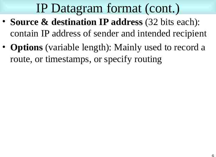
IP Datagram format (cont.) Source & destination IP address (32 bits each): contain IP address of sender and intended recipient Options (variable length): Mainly used to record a route, or timestamps, or specify routing 6
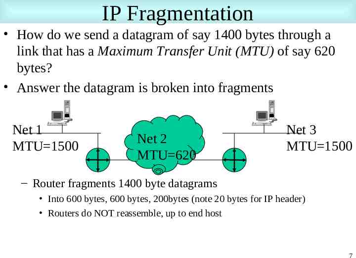
IP Fragmentation How do we send a datagram of say 1400 bytes through a link that has a Maximum Transfer Unit (MTU) of say 620 bytes? Answer the datagram is broken into fragments Net 1 MTU 1500 Net 2 MTU 620 Net 3 MTU 1500 – Router fragments 1400 byte datagrams Into 600 bytes, 600 bytes, 200bytes (note 20 bytes for IP header) Routers do NOT reassemble, up to end host 7
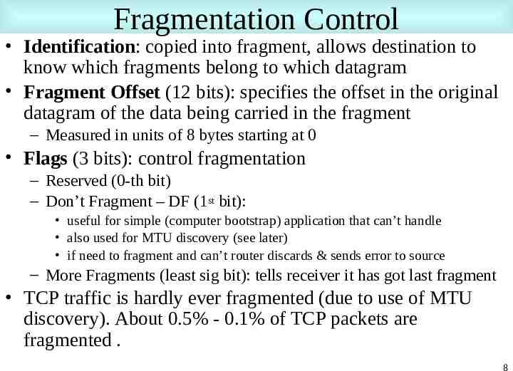
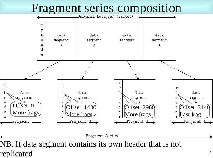
Fragmentation Control Identification: copied into fragment, allows destination to know which fragments belong to which datagram Fragment Offset (12 bits): specifies the offset in the original datagram of the data being carried in the fragment – Measured in units of 8 bytes starting at 0 Flags (3 bits): control fragmentation – Reserved (0-th bit) – Don’t Fragment – DF (1st bit): useful for simple (computer bootstrap) application that can’t handle also used for MTU discovery (see later) if need to fragment and can’t router discards & sends error to source – More Fragments (least sig bit): tells receiver it has got last fragment TCP traffic is hardly ever fragmented (due to use of MTU discovery). About 0.5% - 0.1% of TCP packets are fragmented . 8
Fragment series composition Offset 0 More frags Offset 1480 More frags Offset 2960 More frags Offset 3440 Last frag NB. If data segment contains its own header that is not replicated 9
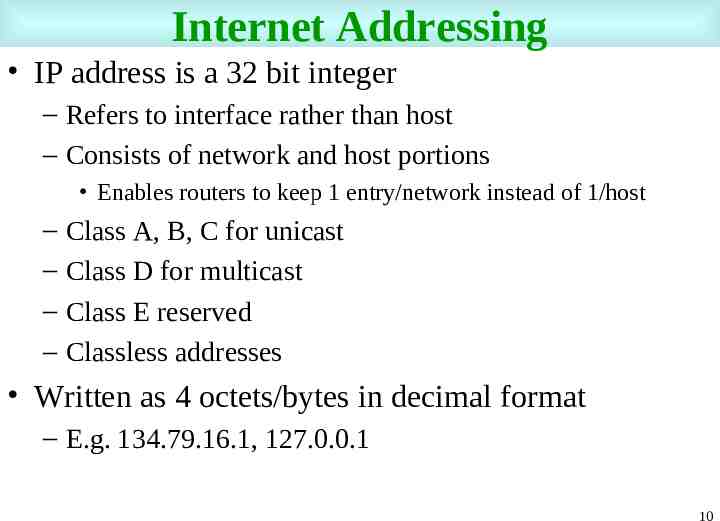
Internet Addressing IP address is a 32 bit integer – Refers to interface rather than host – Consists of network and host portions Enables routers to keep 1 entry/network instead of 1/host – – – – Class A, B, C for unicast Class D for multicast Class E reserved Classless addresses Written as 4 octets/bytes in decimal format – E.g. 134.79.16.1, 127.0.0.1 10
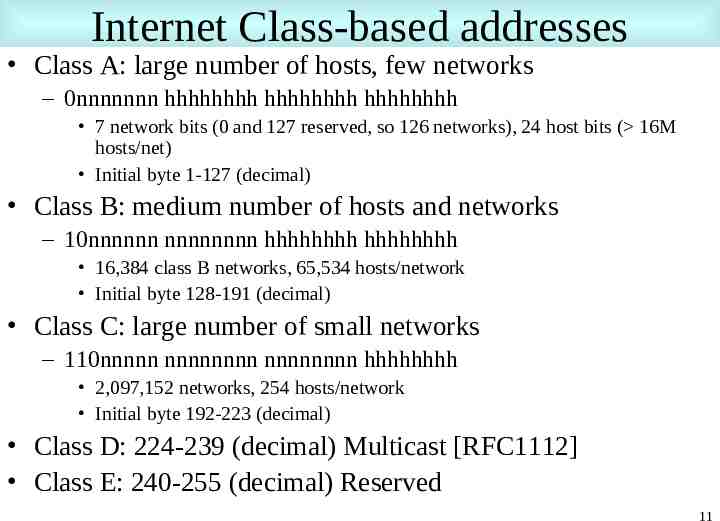
Internet Class-based addresses Class A: large number of hosts, few networks – 0nnnnnnn hhhhhhhh hhhhhhhh hhhhhhhh 7 network bits (0 and 127 reserved, so 126 networks), 24 host bits ( 16M hosts/net) Initial byte 1-127 (decimal) Class B: medium number of hosts and networks – 10nnnnnn nnnnnnnn hhhhhhhh hhhhhhhh 16,384 class B networks, 65,534 hosts/network Initial byte 128-191 (decimal) Class C: large number of small networks – 110nnnnn nnnnnnnn nnnnnnnn hhhhhhhh 2,097,152 networks, 254 hosts/network Initial byte 192-223 (decimal) Class D: 224-239 (decimal) Multicast [RFC1112] Class E: 240-255 (decimal) Reserved 11
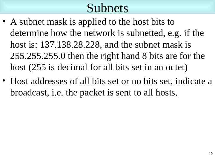
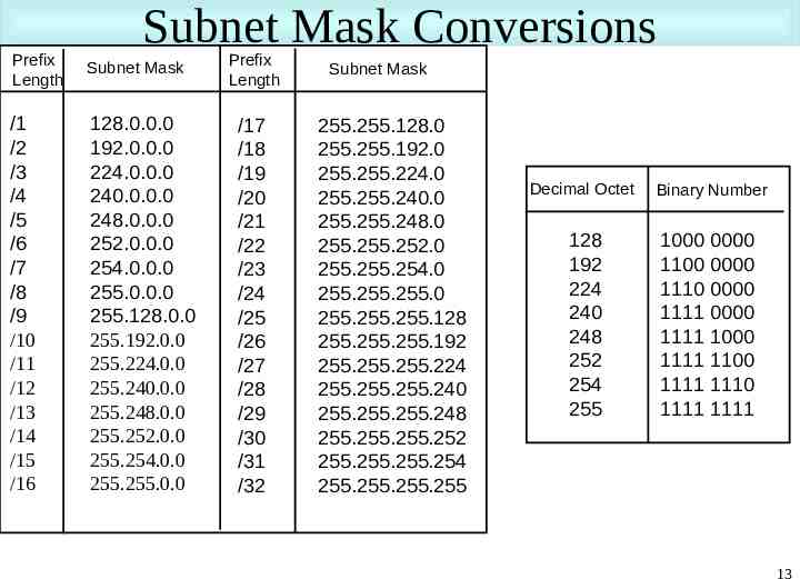
Subnets A subnet mask is applied to the host bits to determine how the network is subnetted, e.g. if the host is: 137.138.28.228, and the subnet mask is 255.255.255.0 then the right hand 8 bits are for the host (255 is decimal for all bits set in an octet) Host addresses of all bits set or no bits set, indicate a broadcast, i.e. the packet is sent to all hosts. 12
Subnet Mask Conversions Prefix Length Subnet Mask /1 /2 /3 /4 /5 /6 /7 /8 /9 /10 /11 /12 /13 /14 /15 /16 128.0.0.0 192.0.0.0 224.0.0.0 240.0.0.0 248.0.0.0 252.0.0.0 254.0.0.0 255.0.0.0 255.128.0.0 255.192.0.0 255.224.0.0 255.240.0.0 255.248.0.0 255.252.0.0 255.254.0.0 255.255.0.0 Prefix Length /17 /18 /19 /20 /21 /22 /23 /24 /25 /26 /27 /28 /29 /30 /31 /32 Subnet Mask 255.255.128.0 255.255.192.0 255.255.224.0 255.255.240.0 255.255.248.0 255.255.252.0 255.255.254.0 255.255.255.0 255.255.255.128 255.255.255.192 255.255.255.224 255.255.255.240 255.255.255.248 255.255.255.252 255.255.255.254 255.255.255.255 Decimal Octet Binary Number 128 192 224 240 248 252 254 255 1000 0000 1100 0000 1110 0000 1111 0000 1111 1000 1111 1100 1111 1110 1111 1111 13
Address depletion In 1991 IAB identified 3 dangers – Running out of class B addresses – Increase in nets has resulted in routing table explosion – Increase in net/hosts exhausting 32 bit address space Four strategies to address – Creative address space allocation {RFC 2050} – Private addresses {RFC 1918}, Network Address Translation (NAT) {RFC 1631} – Classless InterDomain Routing (CIDR) {RFC 1519} – IP version 6 (IPv6) {RFC 1883} 14
Creative IP address allocation Class A addresses 64 – 127 reserved – Handle on individual basis Class B only assigned given a demonstrated need Class C – divided up into 8 blocks allocated to regional authorities – 208-223 remains unassigned and unallocated Three main registries handle assignments – APNIC – Asia & Pacific www.apnic.net – ARIN – N. & S. America, Caribbean & sub-Saharan Africa www.arin.net – RIPE – Europe and surrounding areas www.ripe.net 15
Private IP Addresses IP addresses that are not globally unique, but used exclusively in an organization Three ranges: – 10.0.0.0 - 10.255.255.255 a single class A net – 172.16.0.0 - 172.31.255.255 16 contiguous class Bs – 192.168.0.0 – 192.168.255.255 256 contiguous class Cs Connectivity provided by Network Address Translator (NAT) – translates outgoing private IP address to Internet IP address, and a return Internet IP address to a private address – Only for TCP/UDP packets 16
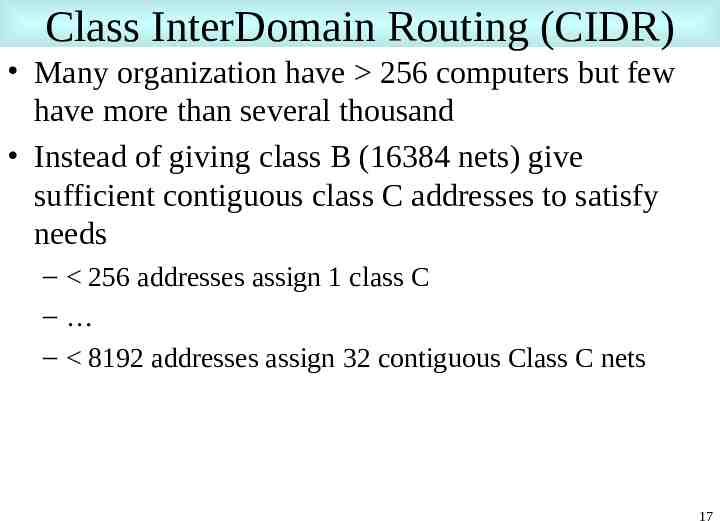
Class InterDomain Routing (CIDR) Many organization have 256 computers but few have more than several thousand Instead of giving class B (16384 nets) give sufficient contiguous class C addresses to satisfy needs – 256 addresses assign 1 class C – – 8192 addresses assign 32 contiguous Class C nets 17
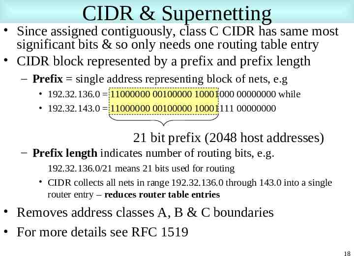
CIDR & Supernetting Since assigned contiguously, class C CIDR has same most significant bits & so only needs one routing table entry CIDR block represented by a prefix and prefix length – Prefix single address representing block of nets, e.g 192.32.136.0 11000000 00100000 10001000 00000000 while 192.32.143.0 11000000 00100000 10001111 00000000 21 bit prefix (2048 host addresses) – Prefix length indicates number of routing bits, e.g. 192.32.136.0/21 means 21 bits used for routing CIDR collects all nets in range 192.32.136.0 through 143.0 into a single router entry – reduces router table entries Removes address classes A, B & C boundaries For more details see RFC 1519 18
Address Recognition Protocol (ARP) IP address is at network layer, need to map it to the MAC (Ethernet address) link layer address Use ARP to map 48 bit Ethernet address to 32 bit IP – IP requests MAC address for IP address from local ARP table – If not there, then an ARP request packet for IP address is sent using physical broadcast address (all FFFs) – Host with requested IP address responds with its MAC address as a unicast packet – On return, host updates ARP table and returns MAC address – ARP cache times out – ARP packets are on top of Ethernet 19
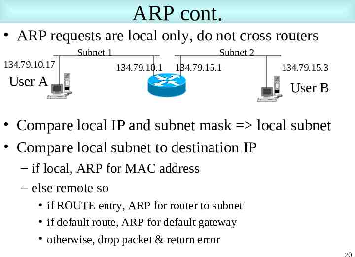
ARP cont. ARP requests are local only, do not cross routers Subnet 1 134.79.10.17 134.79.10.1 Subnet 2 134.79.15.1 User A 134.79.15.3 User B Compare local IP and subnet mask local subnet Compare local subnet to destination IP – if local, ARP for MAC address – else remote so if ROUTE entry, ARP for router to subnet if default route, ARP for default gateway otherwise, drop packet & return error 20
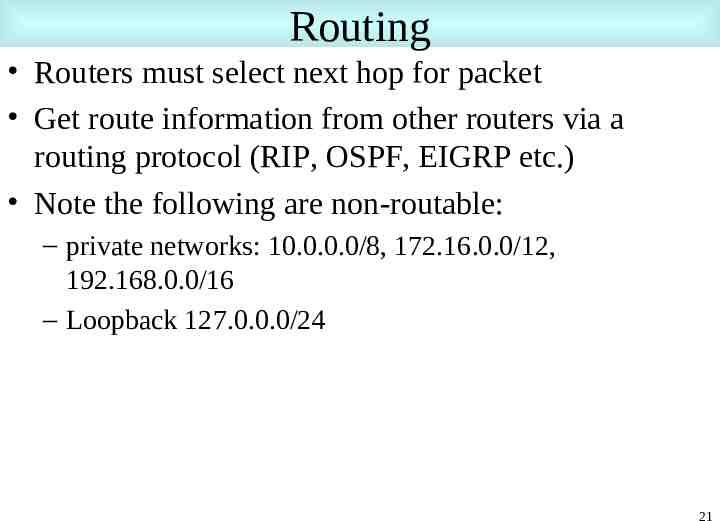
Routing Routers must select next hop for packet Get route information from other routers via a routing protocol (RIP, OSPF, EIGRP etc.) Note the following are non-routable: – private networks: 10.0.0.0/8, 172.16.0.0/12, 192.168.0.0/16 – Loopback 127.0.0.0/24 21
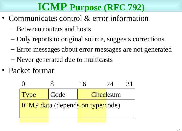
ICMP Purpose (RFC 792) Communicates control & error information – – – – Between routers and hosts Only reports to original source, suggests corrections Error messages about error messages are not generated Never generated due to multicasts Packet format 0 8 16 24 31 Type Code Checksum ICMP data (depends on type/code) 22
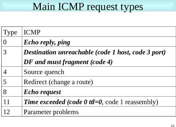
Main ICMP request types Type ICMP 0 Echo reply, ping 3 Destination unreachable (code 1 host, code 3 port) DF and must fragment (code 4) 4 Source quench 5 Redirect (change a route) 8 Echo request 11 Time exceeded (code 0 ttl 0, code 1 reassembly) 12 Parameter problems 23
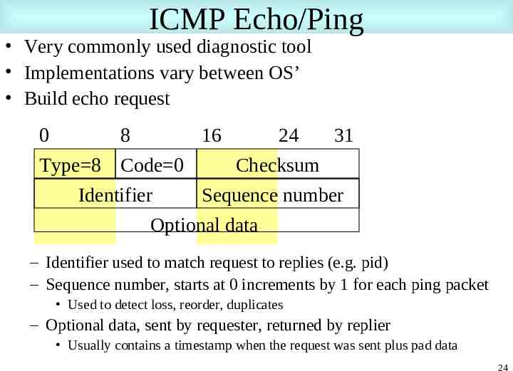
ICMP Echo/Ping Very commonly used diagnostic tool Implementations vary between OS’ Build echo request 0 8 16 24 31 Type 8 Code 0 Checksum Identifier Sequence number Optional data – Identifier used to match request to replies (e.g. pid) – Sequence number, starts at 0 increments by 1 for each ping packet Used to detect loss, reorder, duplicates – Optional data, sent by requester, returned by replier Usually contains a timestamp when the request was sent plus pad data 24
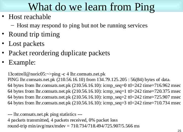
What do we learn from Ping Host reachable – Host may respond to ping but not be running services Round trip timing Lost packets Packet reordering duplicate packets Example: 13cottrell@noric05: ping -c 4 lhr.comsats.net.pk PING lhr.comsats.net.pk (210.56.16.10) from 134.79.125.205 : 56(84) bytes of data. 64 bytes from lhr.comsats.net.pk (210.56.16.10): icmp seq 0 ttl 242 time 716.962 msec 64 bytes from lhr.comsats.net.pk (210.56.16.10): icmp seq 1 ttl 242 time 720.375 msec 64 bytes from lhr.comsats.net.pk (210.56.16.10): icmp seq 2 ttl 242 time 725.907 msec 64 bytes from lhr.comsats.net.pk (210.56.16.10): icmp seq 3 ttl 242 time 710.734 msec --- lhr.comsats.net.pk ping statistics --4 packets transmitted, 4 packets received, 0% packet loss round-trip min/avg/max/mdev 710.734/718.494/725.907/5.566 ms 25
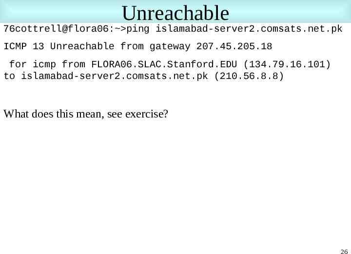
Unreachable 76cottrell@flora06: ping islamabad-server2.comsats.net.pk ICMP 13 Unreachable from gateway 207.45.205.18 for icmp from FLORA06.SLAC.Stanford.EDU (134.79.16.101) to islamabad-server2.comsats.net.pk (210.56.8.8) What does this mean, see exercise? 26
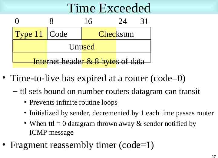
Time Exceeded 0 8 Type 11 Code 16 24 31 Checksum Unused Internet header & 8 bytes of data Time-to-live has expired at a router (code 0) – ttl sets bound on number routers datagram can transit Prevents infinite routine loops Initialized by sender, decremented by 1 each time passes router When ttl 0 datagram thrown away & sender notified by ICMP message Fragment reassembly timer (code 1) 27
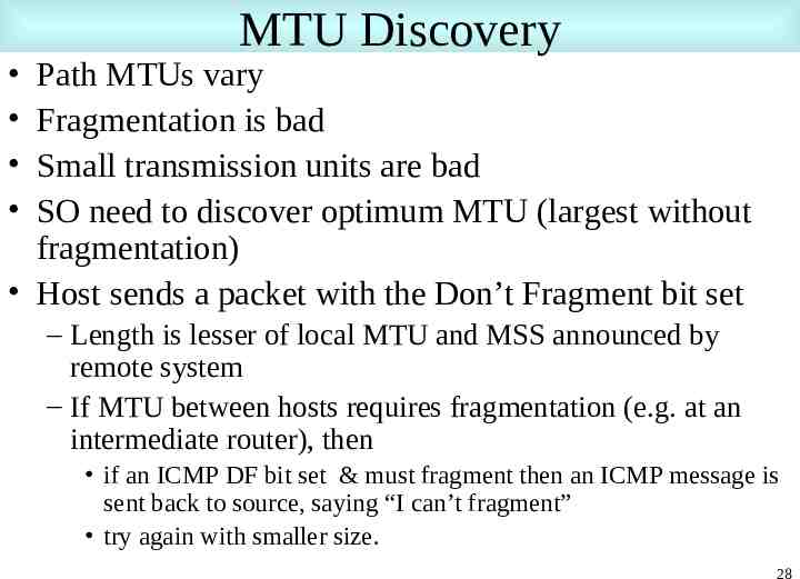
MTU Discovery Path MTUs vary Fragmentation is bad Small transmission units are bad SO need to discover optimum MTU (largest without fragmentation) Host sends a packet with the Don’t Fragment bit set – Length is lesser of local MTU and MSS announced by remote system – If MTU between hosts requires fragmentation (e.g. at an intermediate router), then if an ICMP DF bit set & must fragment then an ICMP message is sent back to source, saying “I can’t fragment” try again with smaller size. 28
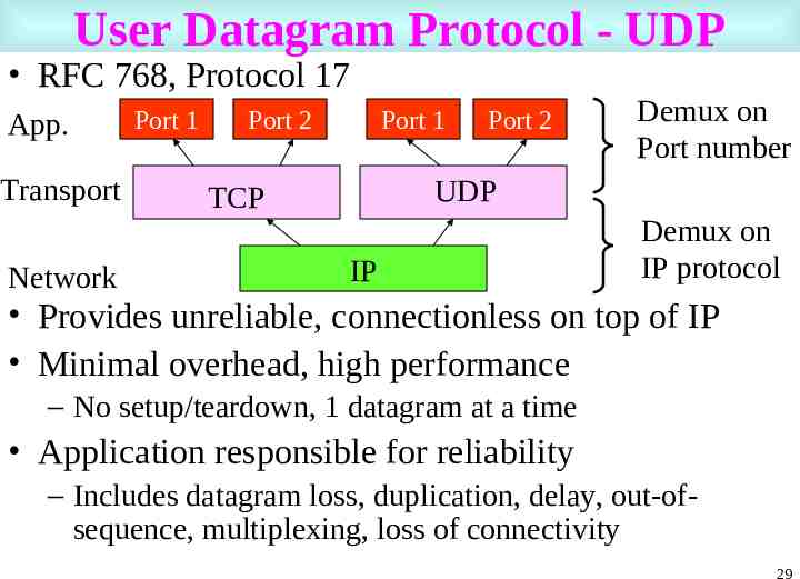
User Datagram Protocol - UDP RFC 768, Protocol 17 App. Transport Network Port 1 Port 2 Port 1 Port 2 Demux on Port number UDP TCP IP Demux on IP protocol Provides unreliable, connectionless on top of IP Minimal overhead, high performance – No setup/teardown, 1 datagram at a time Application responsible for reliability – Includes datagram loss, duplication, delay, out-ofsequence, multiplexing, loss of connectivity 29
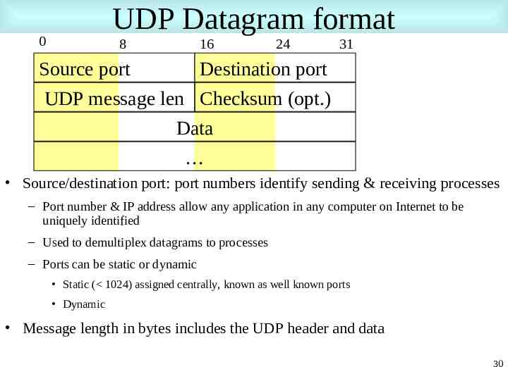
UDP Datagram format 0 8 16 24 31 Source port Destination port UDP message len Checksum (opt.) Data Source/destination port: port numbers identify sending & receiving processes – Port number & IP address allow any application in any computer on Internet to be uniquely identified – Used to demultiplex datagrams to processes – Ports can be static or dynamic Static ( 1024) assigned centrally, known as well known ports Dynamic Message length in bytes includes the UDP header and data 30
UDP applications Message oriented, e.g. SNMP, DNS, time File system, e.g. NFS, AFS Lightweight file transfer, e.g. tftp, bootp 31
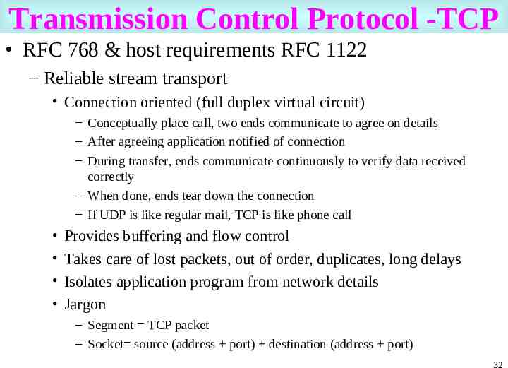
Transmission Control Protocol -TCP RFC 768 & host requirements RFC 1122 – Reliable stream transport Connection oriented (full duplex virtual circuit) – Conceptually place call, two ends communicate to agree on details – After agreeing application notified of connection – During transfer, ends communicate continuously to verify data received correctly – When done, ends tear down the connection – If UDP is like regular mail, TCP is like phone call Provides buffering and flow control Takes care of lost packets, out of order, duplicates, long delays Isolates application program from network details Jargon – Segment TCP packet – Socket source (address port) destination (address port) 32
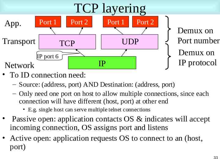
TCP layering Port 1 App. Transport Port 2 Port 1 UDP TCP IP port 6 Network Port 2 IP Demux on Port number Demux on IP protocol To ID connection need: – Source: (address, port) AND Destination: (address, port) – Only need one port on host to allow multiple connections, since each connection will have different (host, port) at other end E.g. single host can serve multiple telnet connections Passive open: application contacts OS & indicates will accept incoming connection, OS assigns port and listens Active open: application requests OS to connect to an (host, port) 33
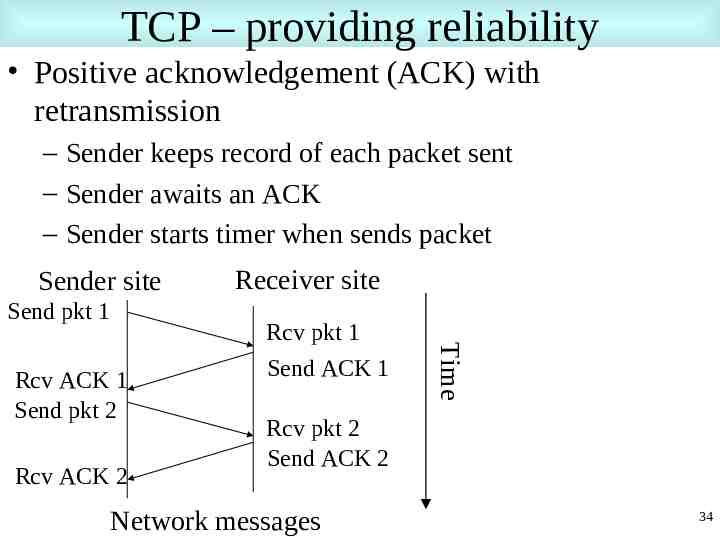
TCP – providing reliability Positive acknowledgement (ACK) with retransmission – Sender keeps record of each packet sent – Sender awaits an ACK – Sender starts timer when sends packet Sender site Send pkt 1 Rcv ACK 2 Rcv pkt 1 Send ACK 1 Time Rcv ACK 1 Send pkt 2 Receiver site Rcv pkt 2 Send ACK 2 Network messages 34
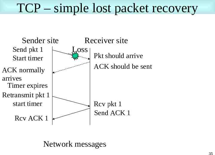
TCP – simple lost packet recovery Sender site Send pkt 1 Start timer ACK normally arrives Timer expires Retransmit pkt 1 start timer Rcv ACK 1 Receiver site Loss Pkt should arrive ACK should be sent Rcv pkt 1 Send ACK 1 Network messages 35
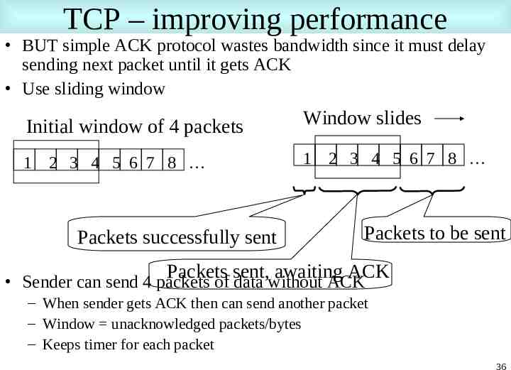
TCP – improving performance BUT simple ACK protocol wastes bandwidth since it must delay sending next packet until it gets ACK Use sliding window Initial window of 4 packets 1 2 3 4 5 6 7 8 Packets successfully sent Window slides 1 2 3 4 5 6 7 8 Packets to be sent Packets sent, awaiting ACK Sender can send 4 packets of data without ACK – When sender gets ACK then can send another packet – Window unacknowledged packets/bytes – Keeps timer for each packet 36
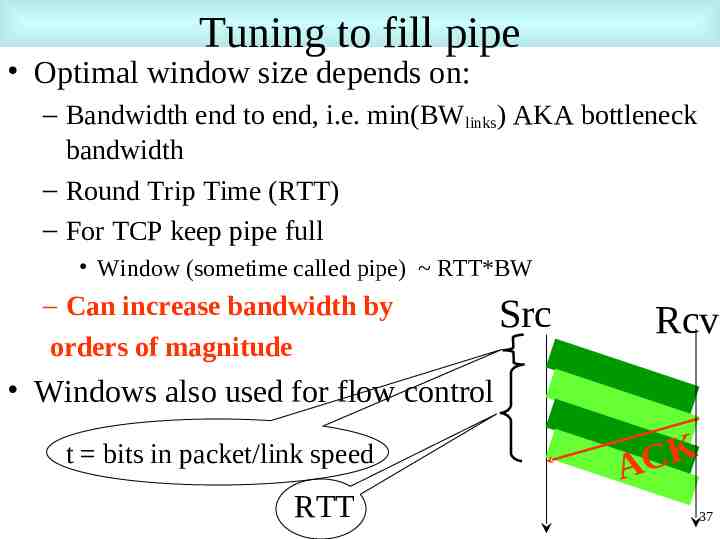
Tuning to fill pipe Optimal window size depends on: – Bandwidth end to end, i.e. min(BWlinks) AKA bottleneck bandwidth – Round Trip Time (RTT) – For TCP keep pipe full Window (sometime called pipe) RTT*BW – Can increase bandwidth by orders of magnitude Src Rcv Windows also used for flow control t bits in packet/link speed RTT K C A 37
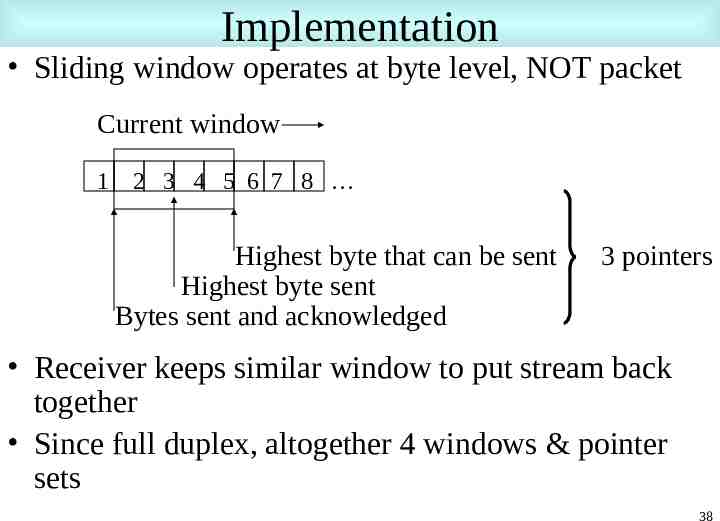
Implementation Sliding window operates at byte level, NOT packet Current window 1 2 3 4 5 6 7 8 Highest byte that can be sent Highest byte sent Bytes sent and acknowledged 3 pointers Receiver keeps similar window to put stream back together Since full duplex, altogether 4 windows & pointer sets 38
TCP flow control Windows vary over time – Receiver advertises (in ACKs) how many it can receive Based on buffers etc. available – Sender adjusts its window to match advertisement – If receiver buffers fill, it sends smaller adverts Used to match buffer requirements of receiver Also used to address congestion control (e.g. in intermediate routers) 39
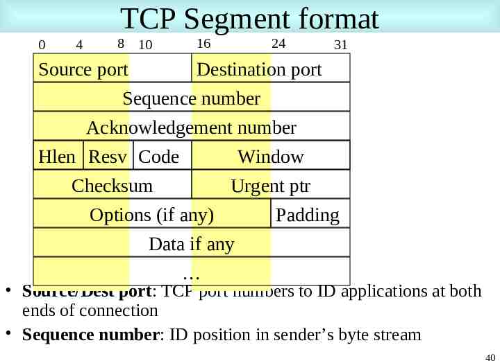
TCP Segment format 0 4 8 10 16 24 31 Source port Destination port Sequence number Acknowledgement number Hlen Resv Code Window Checksum Urgent ptr Options (if any) Padding Data if any Source/Dest port: TCP port numbers to ID applications at both ends of connection Sequence number: ID position in sender’s byte stream 40
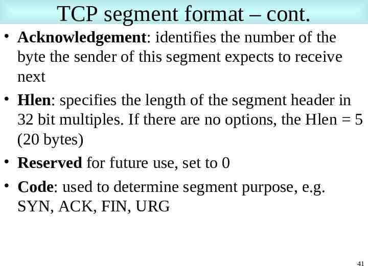
TCP segment format – cont. Acknowledgement: identifies the number of the byte the sender of this segment expects to receive next Hlen: specifies the length of the segment header in 32 bit multiples. If there are no options, the Hlen 5 (20 bytes) Reserved for future use, set to 0 Code: used to determine segment purpose, e.g. SYN, ACK, FIN, URG 41
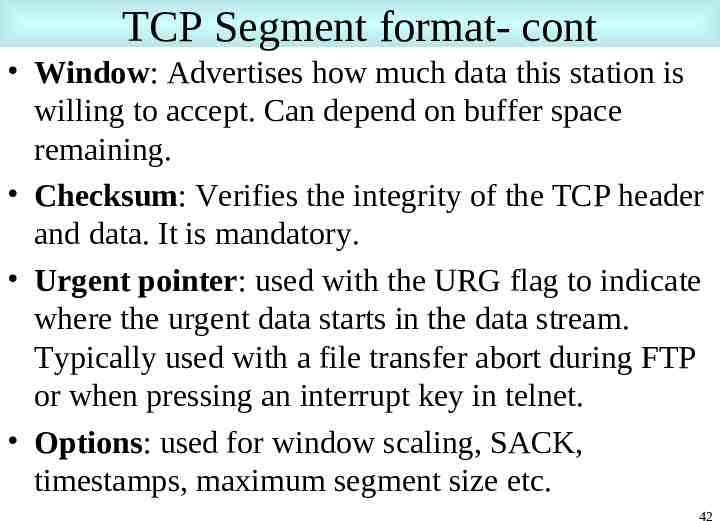
TCP Segment format- cont Window: Advertises how much data this station is willing to accept. Can depend on buffer space remaining. Checksum: Verifies the integrity of the TCP header and data. It is mandatory. Urgent pointer: used with the URG flag to indicate where the urgent data starts in the data stream. Typically used with a file transfer abort during FTP or when pressing an interrupt key in telnet. Options: used for window scaling, SACK, timestamps, maximum segment size etc. 42
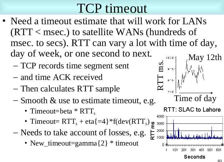
TCP timeout – – – – RTT ms. Need a timeout estimate that will work for LANs (RTT msec.) to satellite WANs (hundreds of msec. to secs). RTT can vary a lot with time of day, day of week, or one second to next. May 12th TCP records time segment sent and time ACK received Then calculates RTT sample Smooth & use to estimate timeout, e.g. Time of day Timeout beta * RTTs Timeout RTTs eta{ 4}*f(dev(RTTs)) – Needs to take account of losses, e.g. New timeout gamma{2} * timeout 43
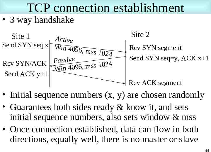
TCP connection establishment 3 way handshake Site 2 Site 1 Active Send SYN seq x Win 4096, m Rcv SYN/ACK Send ACK y 1 ss 1024 Passive 4 2 0 1 s s m , 6 9 Win 40 Rcv SYN segment Send SYN seq y, ACK x 1 Rcv ACK segment Initial sequence numbers (x, y) are chosen randomly Guarantees both sides ready & know it, and sets initial sequence numbers, also sets window & mss Once connection established, data can flow in both directions, equally well, there is no master or slave 44
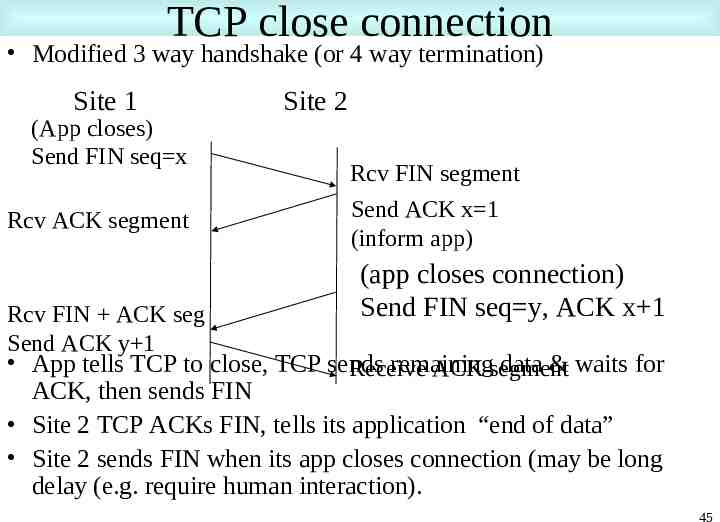
TCP close connection Modified 3 way handshake (or 4 way termination) Site 1 (App closes) Send FIN seq x Rcv ACK segment Rcv FIN ACK seg Send ACK y 1 Site 2 Rcv FIN segment Send ACK x 1 (inform app) (app closes connection) Send FIN seq y, ACK x 1 App tells TCP to close, TCP sends remaining data & waits for Receive ACK segment ACK, then sends FIN Site 2 TCP ACKs FIN, tells its application “end of data” Site 2 sends FIN when its app closes connection (may be long delay (e.g. require human interaction). 45
More Information Lectures, tutorials etc: – – – – – – www.nv.cc.va.us/home/joney/tcp ip.htm www.cs.pdx.edu/ jrb/tcpip.lectures.html www.raleigh.ibm.com/cgi-bin/bookmgr/BOOKS/EZ306200/CCONTENTS www.cisco.com/univercd/cc/td/doc/product/iaabu/centri4/user/scf4ap1.htm www.cis.ohio-state.edu/htbin/rfc/rfc1180.html www.jbmelectronics.com/tcp.htm Encylopaedia – http://www.freesoft.org/CIE/index.htm TCP/IP Resources – www.private.org.il/tcpip rl.html Understanding IP addresses – http://www.3com.com/solutions/en US/ncs/501302.html Configuring TCP (RFC 1122) – ftp://nic.merit.edu/internet/documents/rfc/rfc1122.txt Assigned protocols, ports etc (RFC 1010) – http://www.es.net/pub/rfcs/rfc1010.txt & /etc/protocols 46
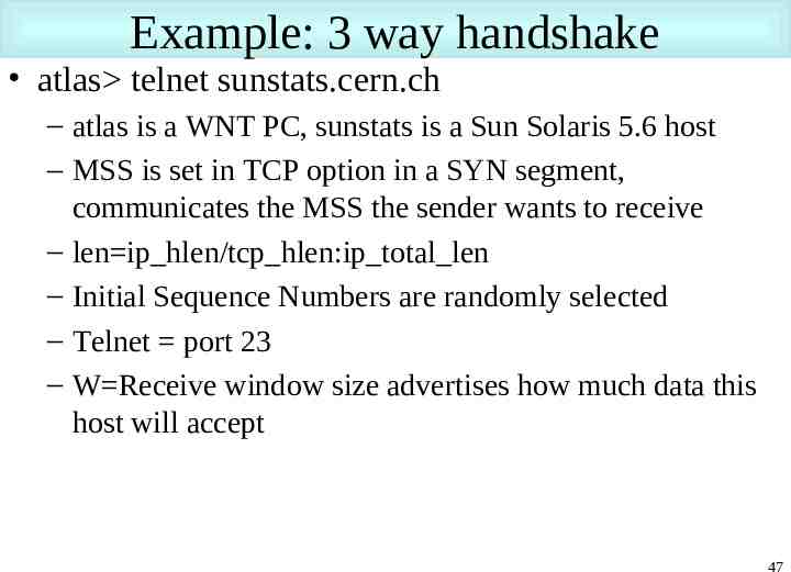
Example: 3 way handshake atlas telnet sunstats.cern.ch – atlas is a WNT PC, sunstats is a Sun Solaris 5.6 host – MSS is set in TCP option in a SYN segment, communicates the MSS the sender wants to receive – len ip hlen/tcp hlen:ip total len – Initial Sequence Numbers are randomly selected – Telnet port 23 – W Receive window size advertises how much data this host will accept 47
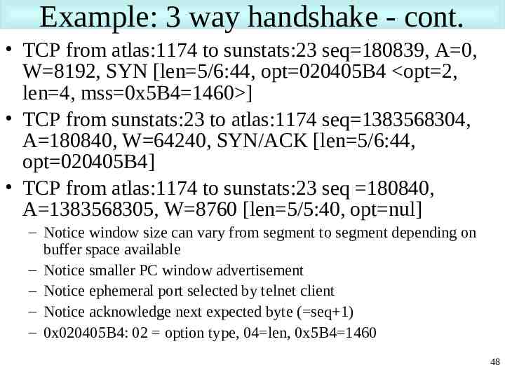
Example: 3 way handshake - cont. TCP from atlas:1174 to sunstats:23 seq 180839, A 0, W 8192, SYN [len 5/6:44, opt 020405B4 opt 2, len 4, mss 0x5B4 1460 ] TCP from sunstats:23 to atlas:1174 seq 1383568304, A 180840, W 64240, SYN/ACK [len 5/6:44, opt 020405B4] TCP from atlas:1174 to sunstats:23 seq 180840, A 1383568305, W 8760 [len 5/5:40, opt nul] – Notice window size can vary from segment to segment depending on buffer space available – Notice smaller PC window advertisement – Notice ephemeral port selected by telnet client – Notice acknowledge next expected byte ( seq 1) – 0x020405B4: 02 option type, 04 len, 0x5B4 1460 48
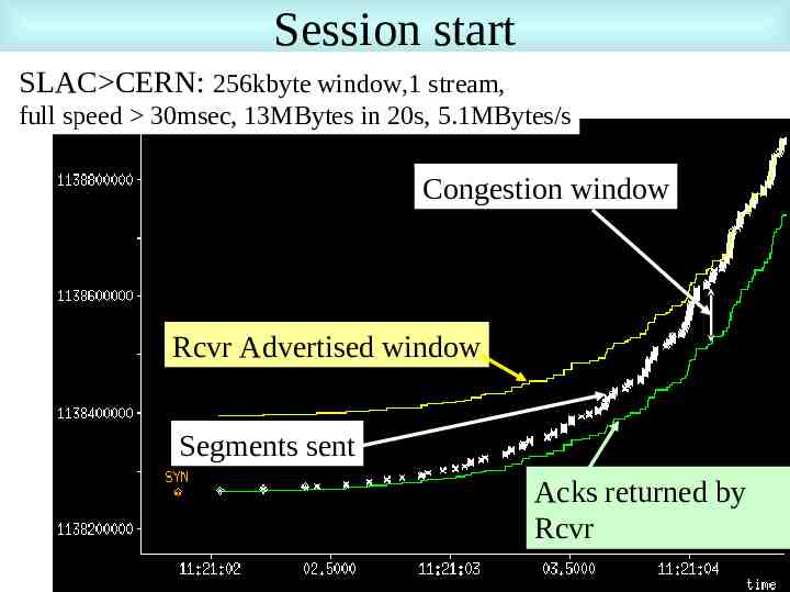
Session start SLAC CERN: 256kbyte window,1 stream, full speed 30msec, 13MBytes in 20s, 5.1MBytes/s Congestion window Rcvr Advertised window Segments sent Acks returned by Rcvr 49