LiFi based Communications Networks: Research Challenges and Solutions


40 Slides9.21 MB
LiFi based Communications Networks: Research Challenges and Solutions Prof. Abhishek Dixit IIT Delhi 2/17/24
Contents Motivations for VLC Research Challenges and Solutions Project & Research activities at IITD Conclusions 2/17/24 Visible Light Communication 2
Contents Motivations for VLC Research Challenges and Solutions Project & Research activities at IITD Conclusions 2/17/24 Visible Light Communication 3
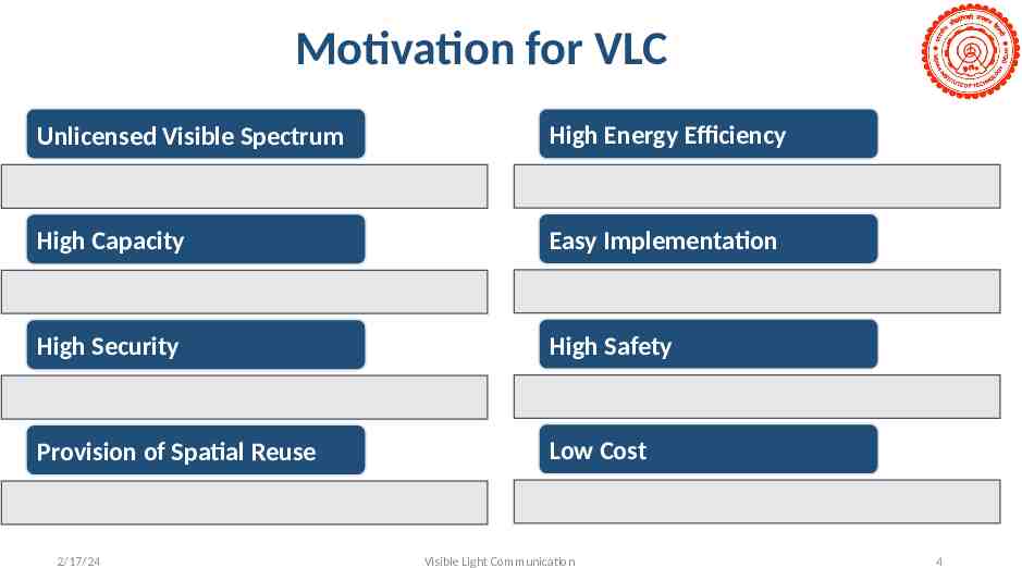
Motivation for VLC Unlicensed Visible Spectrum High Energy Efficiency High Capacity Easy Implementation High Security High Safety Provision of Spatial Reuse Low Cost 2/17/24 Visible Light Communication 4
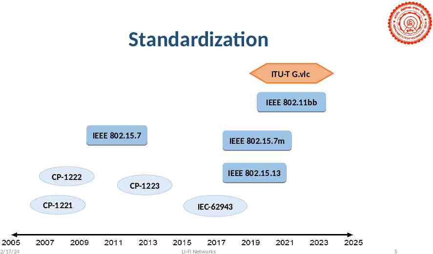
Standardization ITU-T G.vlc IEEE 802.11bb IEEE 802.15.7 CP-1222 CP-1221 2/17/24 IEEE 802.15.7m IEEE 802.15.13 CP-1223 IEC-62943 Li-Fi Networks 5
Contents Motivations for VLC Research Challenges and Solutions Channel Modelling Challenges at the Transmitter Modulation Schemes Multiplexing Techniques Indoor Positioning Systems Media Access Control Project & Research activities at IITD Conclusions 2/17/24 Visible Light Communication 6
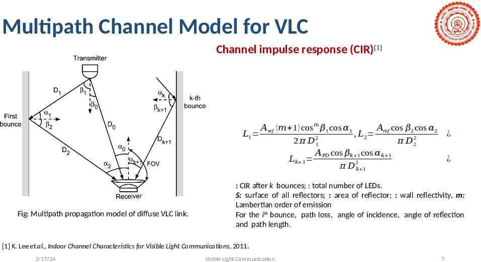
Multipath Channel Model for VLC Channel impulse response (CIR)[1] 𝐿1 Fig: Multipath propagation model of diffuse VLC link. 𝐴ref ( 𝑚 1 ) cos 𝑚 𝛽1 cos 𝛼 1 𝐴ref cos 𝛽 2 cos 𝛼2 , 𝐿 2 2 𝜋 𝐷 21 𝜋 𝐷 22 𝐴PD cos 𝛽𝑘 1 cos 𝛼𝑘 1 𝐿𝑘 1 2 𝜋 𝐷 𝑘 1 ¿ ¿ : CIR after k bounces; : total number of LEDs. S: surface of all reflectors; : area of reflector; : wall reflectivity, m: Lambertian order of emission For the ith bounce, path loss, angle of incidence, angle of reflection and path length. [1] K. Lee et al., Indoor Channel Characteristics for Visible Light Communications, 2011. 2/17/24 Visible Light Communication 7
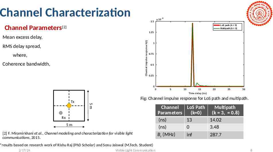
Channel Characterization 10 1.5 Channel Parameters -6 LoS path (k 0) Multipath (k 3) [2] 1.25 Channel impulse response h(t) Mean excess delay, RMS delay spread, where, Coherence bandwidth, 1 0.75 0.5 0.25 0 0 5 10 15 20 25 30 Time delay (ns) Fig: Channel impulse response for LoS path and multipath. 5m Tx Rx 5m [2] F. Miramirkhani et al., Channel modeling and characterization for visible light communications, 2015. Channel Parameters (ns) (ns) Bc (MHz) LoS Path Multipath (k 0) (k 3, 0.8) 13 14.02 0 3.48 inf 287.7 *results based on research work of Rishu Raj (PhD Scholar) and Sonu Jaiswal (M.Tech. Student) 2/17/24 Visible Light Communication 8
Contents Motivations for VLC Research Challenges and Solutions Channel Modelling Challenges at the Transmitter Modulation Schemes Multiplexing Techniques Indoor Positioning Systems Media Access Control Project & Research activities at IITD Conclusions 2/17/24 Visible Light Communication 9
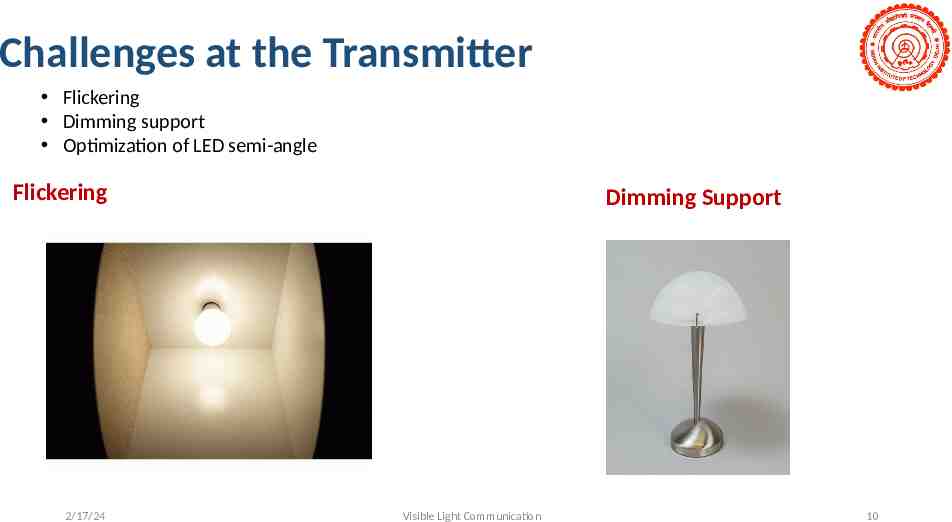
Challenges at the Transmitter Flickering Dimming support Optimization of LED semi-angle Flickering 2/17/24 Dimming Support Visible Light Communication 10
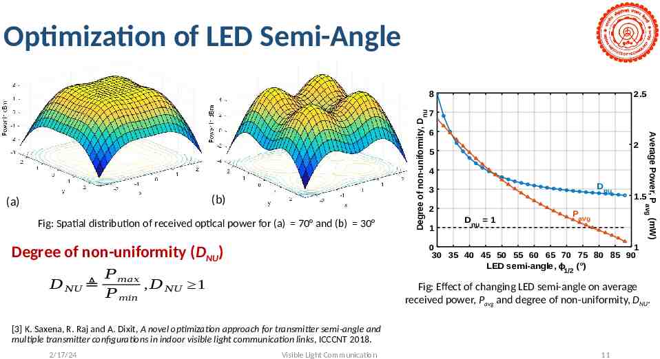
Optimization of LED Semi-Angle Fig: Spatial distribution of received optical power for (a) 70 and (b) 30 7 6 2 5 4 Dnu 3 2 1 D nu 1 Pavg 𝑃 𝑚𝑎𝑥 , 𝐷 𝑁𝑈 1 𝑃 𝑚𝑖𝑛 Fig: Effect of changing LED semi-angle on average received power, Pavg and degree of non-uniformity, DNU. [3] K. Saxena, R. Raj and A. Dixit, A novel optimization approach for transmitter semi-angle and multiple transmitter configurations in indoor visible light communication links, ICCCNT 2018. 2/17/24 1.5 0 1 30 35 40 45 50 55 60 65 70 75 80 85 90 LED semi-angle, ϕ1/2 ( ) Degree of non-uniformity (DNU) 𝐷 𝑁𝑈 2.5 Average Power, P avg (mW) (b) (a) Degree of non-uniformity, D nu 8 Visible Light Communication 11
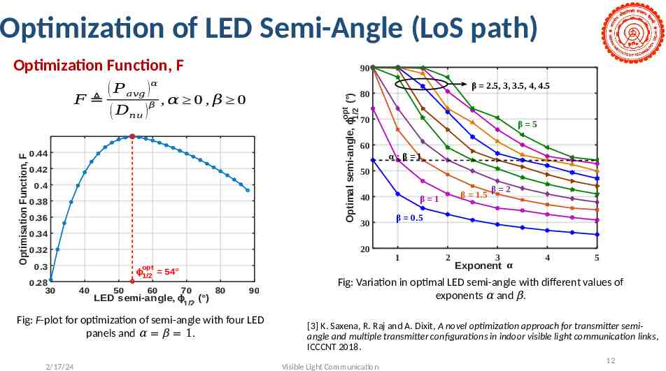
Optimization of LED Semi-Angle (LoS path) Optimization Function, F 90 opt Optimal semi-angle, ϕ1/2 ( ) Optimisation Function, F ( 𝑃 𝑎𝑣𝑔 )𝛼 𝐹 ,𝛼 0 , 𝛽 0 𝛽 ( 𝐷𝑛𝑢 ) 0.44 0.42 0.4 0.38 0.36 β 2.5, 3, 3.5, 4, 4.5 80 70 60 β 5 α:β 1 50 40 30 β 1.5 β 1 β 2 β 0.5 0.34 20 0.32 0.3 0.28 30 opt ϕ1/2 40 50 54 60 70 LED semi-angle, ϕ1/2 ( ) 80 90 Fig: F-plot for optimization of semi-angle with four LED panels and α β 1. 2/17/24 1 2 3 Exponent α 4 5 Fig: Variation in optimal LED semi-angle with different values of exponents α and β. [3] K. Saxena, R. Raj and A. Dixit, A novel optimization approach for transmitter semiangle and multiple transmitter configurations in indoor visible light communication links, ICCCNT 2018. Visible Light Communication 12
Contents Motivations for VLC Research Challenges and Solutions Channel Modelling Challenges at the Transmitter Modulation Schemes Multiplexing Techniques Indoor Positioning Systems Media Access Control Project & Research activities at IITD Conclusions 2/17/24 Visible Light Communication 13
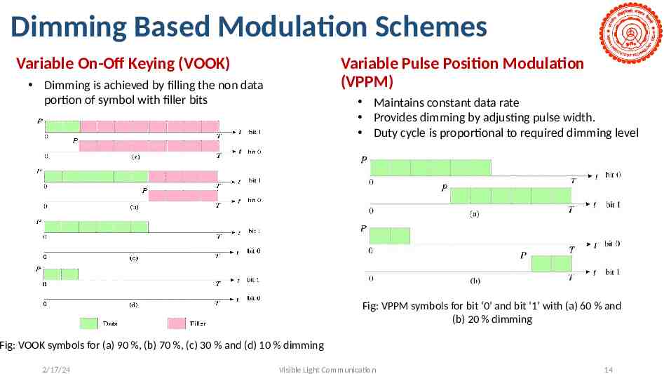
Dimming Based Modulation Schemes Variable On-Off Keying (VOOK) Variable Pulse Position Modulation (VPPM) Dimming is achieved by filling the non data portion of symbol with filler bits Maintains constant data rate Provides dimming by adjusting pulse width. Duty cycle is proportional to required dimming level Fig: VPPM symbols for bit ‘0’ and bit ‘1’ with (a) 60 % and (b) 20 % dimming Fig: VOOK symbols for (a) 90 %, (b) 70 %, (c) 30 % and (d) 10 % dimming 2/17/24 Visible Light Communication 14
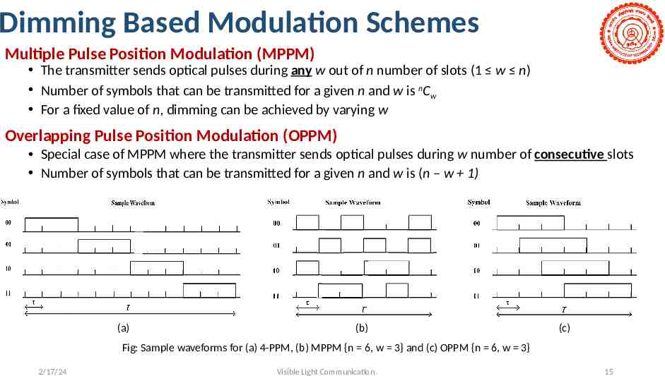
Dimming Based Modulation Schemes Multiple Pulse Position Modulation (MPPM) The transmitter sends optical pulses during any w out of n number of slots (1 w n) Number of symbols that can be transmitted for a given n and w is nCw For a fixed value of n, dimming can be achieved by varying w Overlapping Pulse Position Modulation (OPPM) Special case of MPPM where the transmitter sends optical pulses during w number of consecutive slots Number of symbols that can be transmitted for a given n and w is (n – w 1) (a) (b) (c) Fig: Sample waveforms for (a) 4-PPM, (b) MPPM {n 6, w 3} and (c) OPPM {n 6, w 3} 2/17/24 Visible Light Communication 15
Contents Motivations for VLC Research Challenges and Solutions Channel Modelling Challenges at the Transmitter Modulation Schemes Multiplexing Techniques: OFDM and NOMA Indoor Positioning Systems Media Access Control Project & Research activities at IITD Conclusions 2/17/24 Visible Light Communication 16
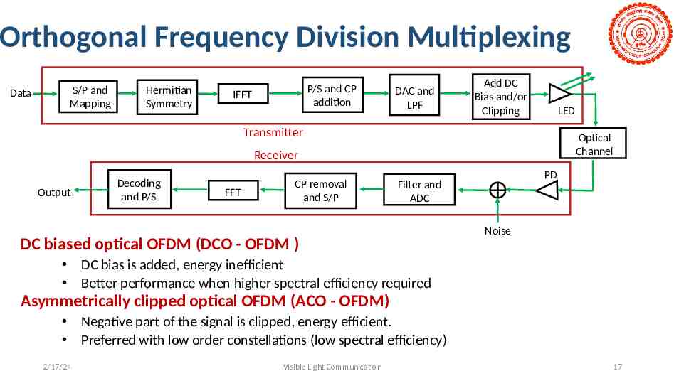
Orthogonal Frequency Division Multiplexing Data S/P and Mapping Hermitian Symmetry P/S and CP addition IFFT DAC and LPF Add DC Bias and/or Clipping LED Transmitter Optical Channel Receiver Output Decoding and P/S FFT CP removal and S/P PD Filter and ADC DC biased optical OFDM (DCO - OFDM ) Noise DC bias is added, energy inefficient Better performance when higher spectral efficiency required Asymmetrically clipped optical OFDM (ACO - OFDM) Negative part of the signal is clipped, energy efficient. Preferred with low order constellations (low spectral efficiency) 2/17/24 Visible Light Communication 17
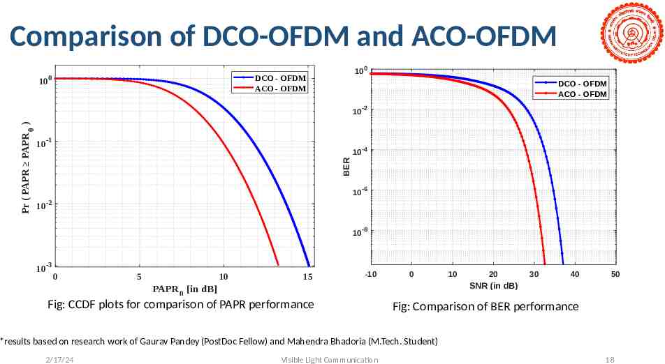
Comparison of DCO-OFDM and ACO-OFDM 10 0 10 0 DCO - OFDM ACO - OFDM DCO - OFDM ACO - OFDM 10 -2 -1 10 -4 BER Pr ( PAPR PAPR 0 ) 10 10 -6 10 -2 10 -8 10-3 0 5 10 15 -10 0 20 30 40 50 SNR (in dB) PAPR 0 [in dB] Fig: CCDF plots for comparison of PAPR performance 10 Fig: Comparison of BER performance *results based on research work of Gaurav Pandey (PostDoc Fellow) and Mahendra Bhadoria (M.Tech. Student) 2/17/24 Visible Light Communication 18
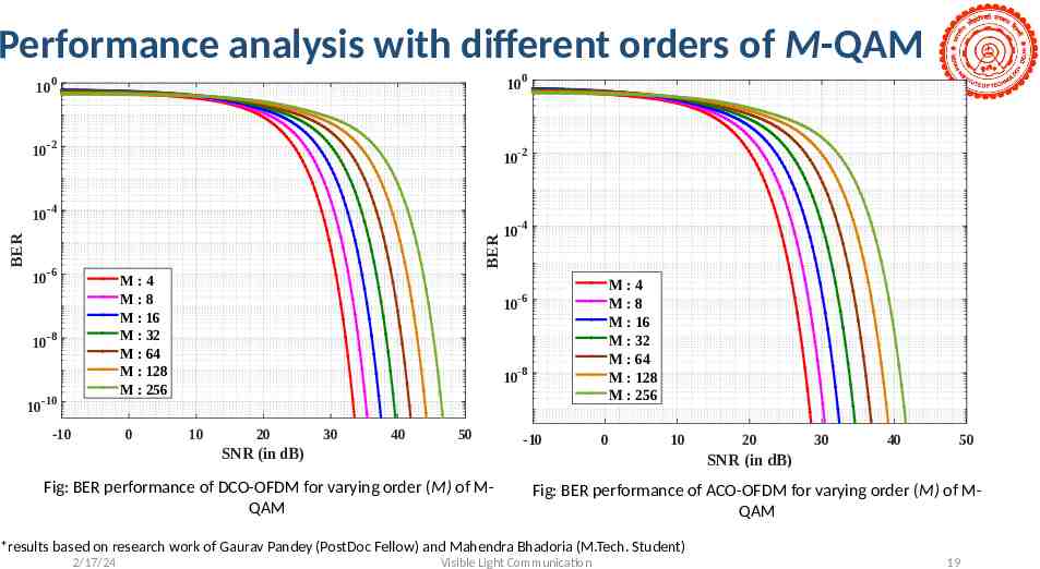
Performance analysis with different orders of M-QAM -2 10 -4 10 -6 BER 10 10 10 100 0 BER 10 M:4 M:8 M : 16 M : 32 M : 64 M : 128 M : 256 -8 -10 -10 0 10 -2 10 -4 10 -6 M:4 M:8 M : 16 M : 32 M : 64 M : 128 M : 256 10-8 10 20 30 40 50 SNR (in dB) -10 0 10 20 30 40 50 SNR (in dB) Fig: BER performance of DCO-OFDM for varying order (M) of MQAM Fig: BER performance of ACO-OFDM for varying order (M) of MQAM *results based on research work of Gaurav Pandey (PostDoc Fellow) and Mahendra Bhadoria (M.Tech. Student) 2/17/24 Visible Light Communication 19
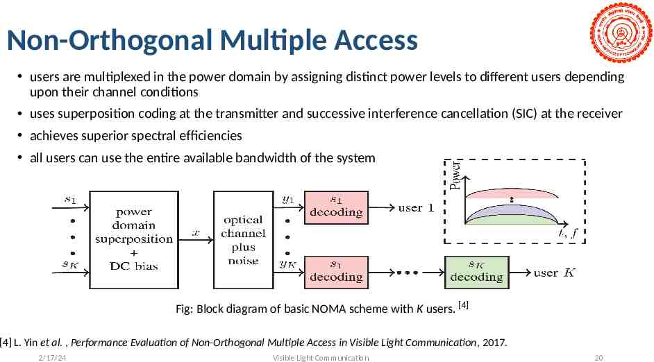
Non-Orthogonal Multiple Access users are multiplexed in the power domain by assigning distinct power levels to different users depending upon their channel conditions uses superposition coding at the transmitter and successive interference cancellation (SIC) at the receiver achieves superior spectral efficiencies all users can use the entire available bandwidth of the system Fig: Block diagram of basic NOMA scheme with K users. [4] [4] L. Yin et al. , Performance Evaluation of Non-Orthogonal Multiple Access in Visible Light Communication, 2017. 2/17/24 Visible Light Communication 20
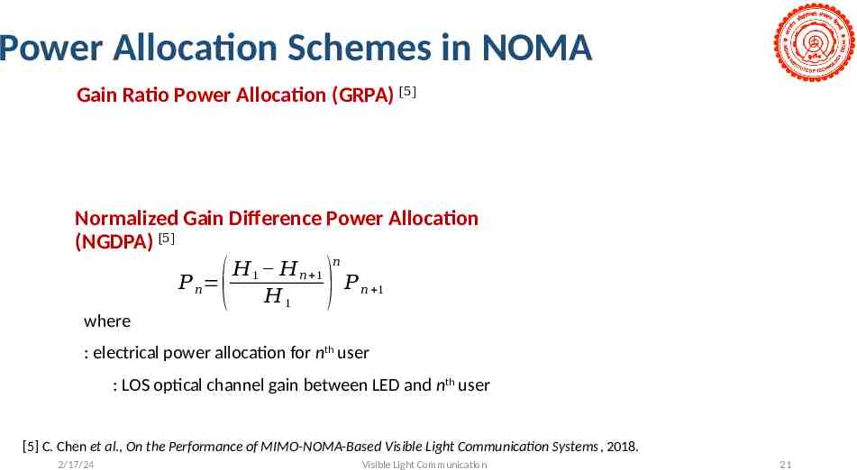
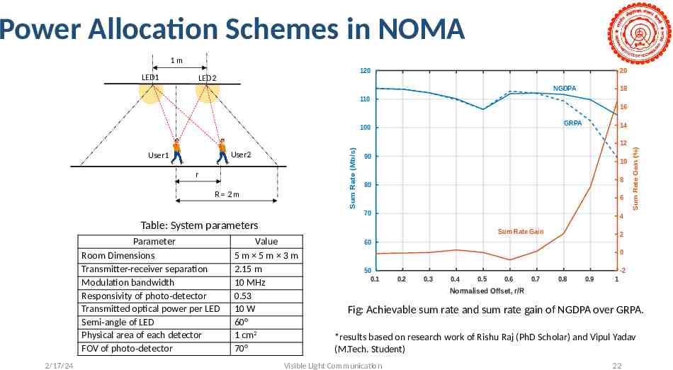
Power Allocation Schemes in NOMA Gain Ratio Power Allocation (GRPA) [5] Normalized Gain Difference Power Allocation (NGDPA) [5] 𝐻 1 𝐻 𝑛 1 𝑃 𝑛 𝐻1 ( 𝑛 ) 𝑃 𝑛 1 where : electrical power allocation for nth user : LOS optical channel gain between LED and nth user [5] C. Chen et al., On the Performance of MIMO-NOMA-Based Visible Light Communication Systems, 2018. 2/17/24 Visible Light Communication 21
Power Allocation Schemes in NOMA 1m 120 LED1 20 LED2 NGDPA 18 110 16 GRPA 14 Sum Rate (Mb/s) 12 User2 User1 r R 2m 90 10 8 80 6 70 4 Table: System parameters Parameter Room Dimensions Transmitter-receiver separation Modulation bandwidth Responsivity of photo-detector Transmitted optical power per LED Semi-angle of LED Physical area of each detector FOV of photo-detector 2/17/24 Sum Rate Gain Value 5m 5m 3m 2.15 m 10 MHz 0.53 10 W 60 1 cm2 70 Sum Rate Gain (%) 100 2 60 0 50 0.1 -2 0.2 0.3 0.4 0.5 0.6 0.7 0.8 0.9 1 Normalised Offset, r/R Fig: Achievable sum rate and sum rate gain of NGDPA over GRPA. *results based on research work of Rishu Raj (PhD Scholar) and Vipul Yadav (M.Tech. Student) Visible Light Communication 22
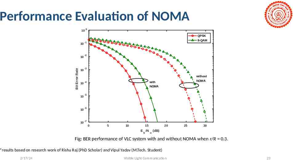
Performance Evaluation of NOMA 10 0 Bit Error Rate QPSK 10 -1 10 -2 10 -3 10 -4 10 -5 10 -6 10 -7 8-QAM without NOMA with NOMA 0 5 10 15 E /N b 20 o 25 30 (dB) Fig: BER performance of VLC system with and without NOMA when r/R 0.3. *results based on research work of Rishu Raj (PhD Scholar) and Vipul Yadav (M.Tech. Student) 2/17/24 Visible Light Communication 23
Contents Motivations for VLC Research Challenges and Solutions Channel Modelling Challenges at the Transmitter Modulation Schemes Multiplexing Techniques Media Access Control Project & Research activities at IITD Conclusions 2/17/24 Visible Light Communication 24
Contents Motivations for VLC Research Challenges and Solutions Channel Modelling Challenges at the Transmitter Modulation Schemes Multiplexing Techniques Indoor Positioning Systems Media Access Control Project & Research activities at IITD Conclusions 2/17/24 Visible Light Communication 25
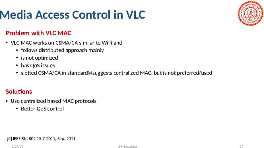
Media Access Control in VLC Problem with VLC MAC VLC MAC works on CSMA/CA similar to WiFi and follows distributed approach mainly is not optimized has QoS issues slotted CSMA/CA in standard[6] suggests centralized MAC, but is not preferred/used Solutions Use centralized based MAC protocols Better QoS control [6] IEEE Std 802.15.7-2011, Sep. 2011. 2/17/24 Li-Fi Networks 26
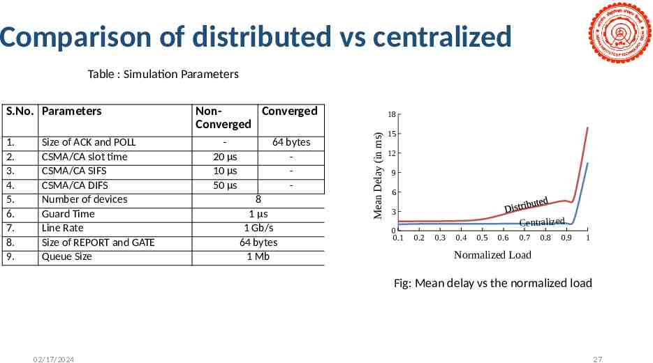
Comparison of distributed vs centralized Table : Simulation Parameters 1. 2. 3. 4. 5. 6. 7. 8. 9. Size of ACK and POLL CSMA/CA slot time CSMA/CA SIFS CSMA/CA DIFS Number of devices Guard Time Line Rate Size of REPORT and GATE Queue Size NonConverged Converged 20 µs 10 µs 50 µs 64 bytes 8 1 µs 1 Gb/s 64 bytes 1 Mb 18 Mean Delay (in ms) S.No. Parameters 15 12 9 6 3 0 0.1 Centralized 0.2 0.3 0.4 0.5 0.6 0.7 0.8 0.9 1 Normalized Load Fig: Mean delay vs the normalized load 02/17/2024 27
Contents Motivations for VLC Research Challenges and Solutions Project & Research activities at IITD Conclusions 2/17/24 Visible Light Communication 28
Li-Fi Project (Subproject of 5G TestBed) IIT Delhi Funding: Department of Telecommunication (DoT), Ministry of Communications, Government of India. End Date: March, 2021 2/17/24 Visible Light Communication 29
Team Structure 2/17/24 S.No. Designation Number of candidates 1. Project Engineer 3 2. Ph.D. student 1 3. Sr. Project Assistant 1 4. Project Associate 2 5. Project Attendant 1 Current team strength 8 Expected team strength 12 Li-Fi Networks 30
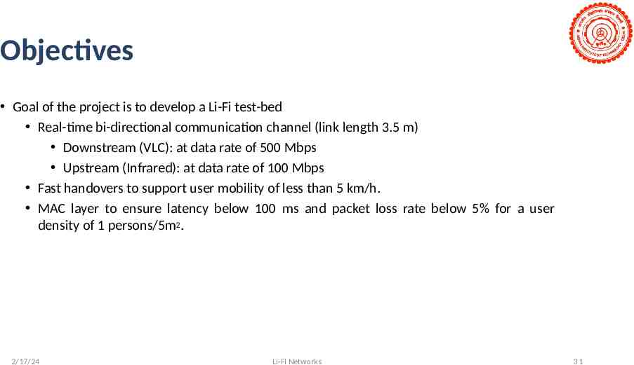
Objectives Goal of the project is to develop a Li-Fi test-bed Real-time bi-directional communication channel (link length 3.5 m) Downstream (VLC): at data rate of 500 Mbps Upstream (Infrared): at data rate of 100 Mbps Fast handovers to support user mobility of less than 5 km/h. MAC layer to ensure latency below 100 ms and packet loss rate below 5% for a user density of 1 persons/5m2. 2/17/24 Li-Fi Networks 31
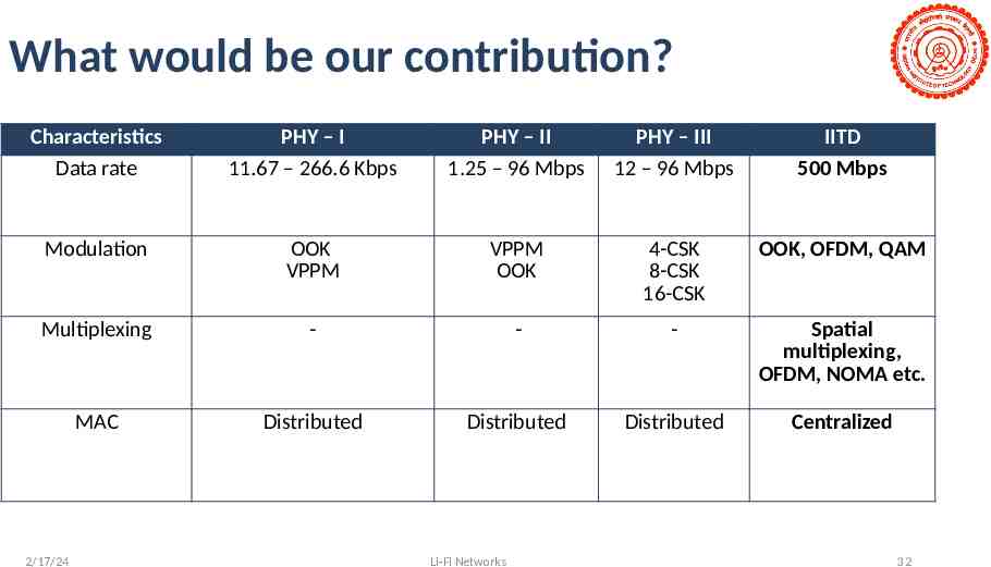
What would be our contribution? Characteristics Data rate PHY – I 11.67 – 266.6 Kbps PHY – II 1.25 – 96 Mbps PHY – III 12 – 96 Mbps IITD 500 Mbps Modulation OOK VPPM VPPM OOK 4-CSK 8-CSK 16-CSK OOK, OFDM, QAM Multiplexing - - - Spatial multiplexing, OFDM, NOMA etc. MAC Distributed Distributed Distributed Centralized 2/17/24 Li-Fi Networks 32
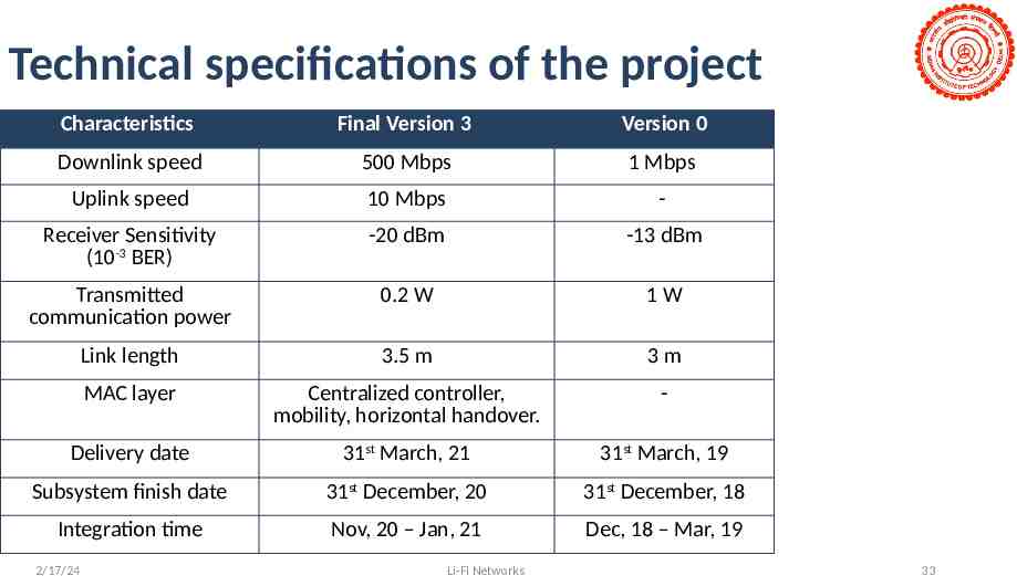
Technical specifications of the project Characteristics Final Version 3 Version 0 Downlink speed 500 Mbps 1 Mbps Uplink speed 10 Mbps - Receiver Sensitivity (10-3 BER) -20 dBm -13 dBm Transmitted communication power 0.2 W 1W Link length 3.5 m 3m MAC layer Centralized controller, mobility, horizontal handover. - Delivery date 31st March, 21 31st March, 19 Subsystem finish date 31st December, 20 31st December, 18 Integration time Nov, 20 – Jan, 21 Dec, 18 – Mar, 19 2/17/24 Li-Fi Networks 33
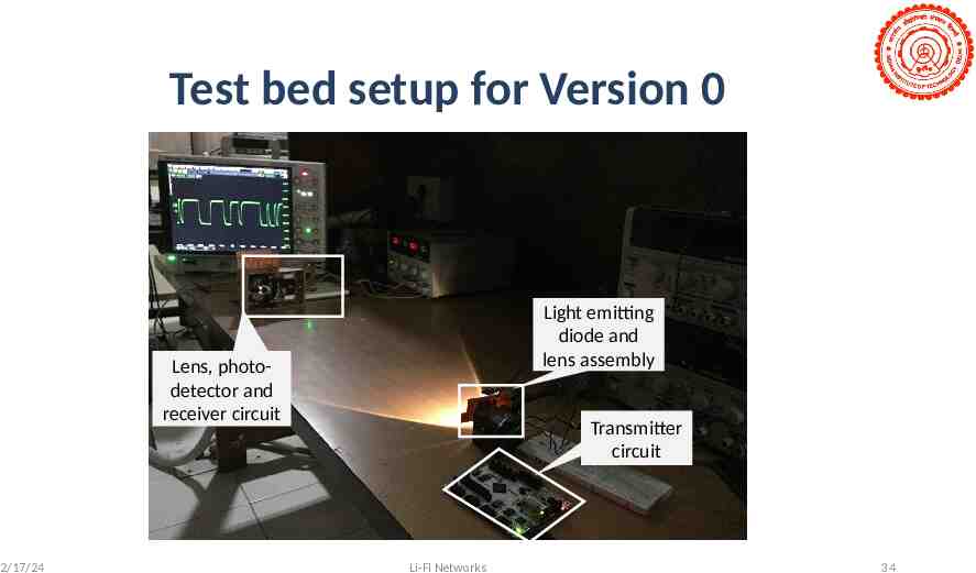
Test bed setup for Version 0 Light emitting diode and lens assembly Lens, photodetector and receiver circuit 2/17/24 Transmitter circuit Li-Fi Networks 34
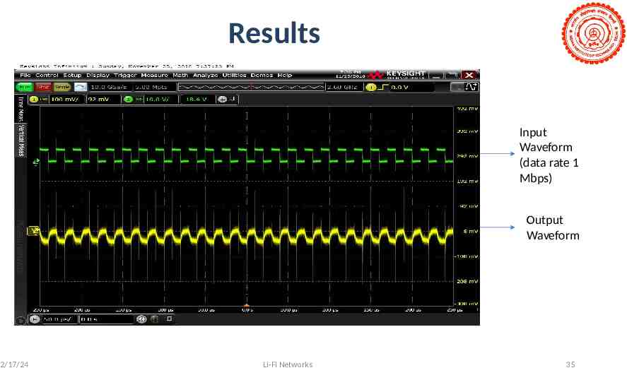
Results Input Waveform (data rate 1 Mbps) Output Waveform 2/17/24 Li-Fi Networks 35
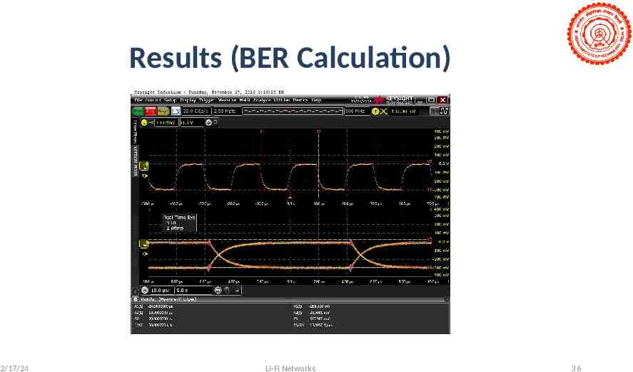
Results (BER Calculation) 2/17/24 Li-Fi Networks 36
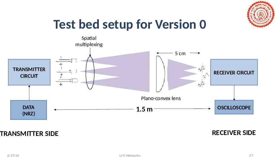
Test bed setup for Version 0 Spatial multiplexing 5 cm TRANSMITTER CIRCUIT RECEIVER CIRCUIT Plano-convex lens DATA (NRZ) 1.5 m RECEIVER SIDE TRANSMITTER SIDE 2/17/24 OSCILLOSCOPE Li-Fi Networks 37
Contents Motivations for VLC Research Challenges and Solutions Project & Research activities at IITD Conclusions 2/17/24 Visible Light Communication 38
Conclusions VLC is a promising technology – data rates, health safe, cheap Targets to get up to 500 Mb/s with right modulation and multiplexing solutions We achieved up to 1 Gb/s with OOK 2/17/24 Visible Light Communication 39
Thank You ! 2/17/24 Visible Light Communication 40