Fins-2 If the pot from previous lecture is made of other materials


8 Slides60.50 KB
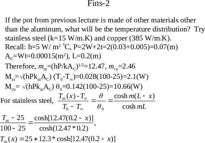
Fins-2 If the pot from previous lecture is made of other materials other than the aluminum, what will be the temperature distribution? Try stainless steel (k 15 W/m.K) and copper (385 W/m.K). Recall: h 5 W/ m2 C, P 2W 2t 2(0.03 0.005) 0.07(m) AC Wt 0.00015(m2), L 0.2(m) Therefore, mss (hP/kAC)1/2 12.47, mcu 2.46 Mss (hPkssAC) (Tb-T ) 0.028(100-25) 2.1(W) Mcu (hPkssAC) b 0.142(100-25) 10.66(W) Tss ( x ) - T cosh m( L x ) For stainless steel, Tb T b cosh mL Tss 25 cosh[12.47(0.2 x )] , 100 25 cosh(12.47 * 0.2) Tss ( x ) 25 12.3 * cosh[12.47(0.2 x )]
Fins-2 (cont.) Tcu ( x ) - T cosh m( L x ) For copper, Tb T b cosh mL Tcu 25 cosh[2.46(0.2 x )] , 100 25 cosh(2.46 * 0.2) Tcu ( x ) 25 66.76 * cosh[2.46(0.2 x )] 100 T( x ) T ss( x ) T cu( x ) 95 copper 90 aluminum 85 80 75 0 stainless steel 0.04 0.08 0.12 x 0.16 0.2
Fins-2 (cont.) Inside the handle of the stainless steel pot, temperature drops quickly. Temperature at the end of the handle is 37.3 C. This is because the stainless steel has low thermal conductivity and heat can not penetrate easily into the handle. Copper has the highest k and, correspondingly, the temperature inside the copper handle distributes more uniformly. Heat easily transfers into the copper handle. Question? Which material is most suitable to be used in a heat sink?
Fins-2 (cont.) How do we know the adiabatic tip assumption is good? Try using the convection heat transfer condition at the tip (case A in fins table) We will use the aluminum pot as the example. h 5 W/m2.K, k 237 W/m.K, m 3.138, M 8.325W Long equation T ( x ) - T cosh[ m( L x )] (h / mk )sinh[m( L x )] Tb T b cosh mL (h / mk )sinh mL cosh[3138 . (0.2 x )] 0.00672 sinh[3138 . (0.2 x )] cosh(0.6276) 0.00672 sinh(0.6276) T ( x ) 25 62.09{cosh(0.6276 3138 . x ) 0.00672 sinh(0.6276 3138 . x )}
Fins-2 (cont.) 100 T: adiabatic tip 96.25 T( x ) T c( x ) Tc: convective tip 92.5 88.75 85 0 0.04 0.08 0.12 0.16 0.2 T(0.2) 87.32 C Tc(0.2) 87.09 C x Note 1: Convective tip case has a slightly lower tip temperature as expected since there is additional heat transfer at the tip. Note 2: there is no significant difference between these two solutions, therefore, correct choice of boundary condition is not that important here. However, sometimes correction might be needed to compensate the effect of convective heat transfer at the end. (especially for thick fins)
Fins-2 (cont.) In some situations, it might be necessary to include the convective heat transfer at the tip. However, one would like to avoid using the long equation as described in case A, fins table. The alternative is to use case B instead and accounts for the convective heat transfer at the tip by extending the fin length L to LC L (t/2). t With convection Original fin length L LC L t/2 L insulation t/2 Then apply the adiabatic condition at the tip of the extended fin as shown above.
Fins-2 (cont.) Use the same example: aluminum pot handle, m 3.138, the length will need to be corrected to LC l (t/2) 0.2 0.0025 0.2025(m) Tcorr ( x ) - T cosh m( Lc x ) Tb T b cosh mLc Tcorr 25 cosh[3138 . (0.2025 x )] , 100 25 cosh(3138 . * 0.2025) Tcorr ( x ) 25 62.05 * cosh[3138 . (0.2025 x )] 100 T( x ) T c( x ) 96.25 92.5 T corr( x ) 88.75 85 0 0.04 0.08 0.12 0.16 0.2 T(0.2) 87.32 C Tc(0.2) 87.09 C Tcorr(0.2025) 87.05 C slight improvement over the uncorrected solution
Correction Length The correction length can be determined by using the formula: Lc L (Ac/P), where Ac is the cross-sectional area and P is the perimeter of the fin at the tip. Thin rectangular fin: Ac Wt, P 2(W t) 2W, since t W Lc L (Ac/P) L (Wt/2W) L (t/2) Cylindrical fin: Ac ( /4)D2, P D, Lc L (Ac/P) L (D/4) Square fin: Ac W2, P 4W, Lc L (Ac/P) L (W2/4W) L (W/4)