Extraction Technology


37 Slides6.18 MB
Extraction Technology
Extraction Process Figure 8.1 Typical liquid-liquid extraction process.
Typical Extractor Light Phase Out Heavy Phase In Light Phase Out Heavy Phase In Light Phase In Light Phase In Heavy Phase Out Light Phase Dispersed Heavy Phase Out Heavy Phase Dispersed
Typical Extractor Extract Out Feed In Solvent In Raffinate Out Light Phase Dispersed
Liquid-liquid Equilibrium f i I f i II x P i i I i xi Pi i vap xi i I xi i II xiI iII I II xi i vap II Phase I Phase II
Design Methods Theoretical Trays Hunter – Nash graphical method Aspen Packed Tower Height Seibert et al. Sieve Tray Efficiency Seibert et al.
Hunter – Nash Graphical Method Blender Material Balance M F S RNp E1 M xM F xF S yS RNp xNp E1y1
Hunter – Nash Graphical Method Figure 8.14 Location of product point.
“P” Point 100 lbs 90 lbs 78 lbs 69 lbs 10 lbs 12 lbs 9 lbs 181 lbs 81 lbs 171 lbs 81 lbs 159 lbs 81 lbs 150 lbs 81 lbs
Hunter – Nash Graphical Method Figure 8.15 Location of operating point.
Hunter – Nash Graphical Method Figure 8.18 Determination of minimum solvent to feed ratio.
Hunter – Nash Graphical Method Figure 8.17 Determination of the number of equilibrium stages.
Graphical Method Example In a continuous counter-current train of mixer settlers, 100 kg/hr of a 40 wt % acetone / 60 wt % water solution is to be reduced to 10 wt % acetone by extraction with pure 1,1,2 trichloroethane (TCE) at 25 C. Find: 1. The minimum solvent rate 2. At 1.8 times the minimum solvent rate, find the number of mixer settlers required. Water Phase ( wt %) TCE Phase ( wt %) C2H3Cl3 Water Acetone C2H3Cl3 Water Acetone 0.73 82.23 17.04 73.76 1.10 25.14 1.02 72.06 26.92 59.21 2.27 38.52 1.17 67.95 30.88 53.92 3.11 42.97 1.60 62.67 35.73 47.53 4.26 48.21 2.10 57.00 40.90 40.00 6.05 53.95 3.75 50.20 46.05 33.70 8.90 57.40 6.52 41.70 51.78 26.26 13.40 60.34
Acetone E1min F Mmin RNp s TCE Water
Acetone E1 F M RNp TCE s Water
10 Minute Problem A feed stream “C” of 100 kg/min containing 30 mass percent solute “A” is being contacted in a single stage stirred contactor with 50 kg/min of pure solvent “S” (equilibrium figure below). Determine the composition and amount of the resulting raffinate and extract streams.
Extractor Sieve Tray Photo of Sieve tray
Trayed Extractor Efficiency (Treybal Empirical Model) 3.12 H t Eo 0.5 Ud Uc 0.42 Where: Ht tray spacing (ft) Ud superficial dispersed phase velocity Uc superficial continuous phase velocity interfacial tension (dyne/cm)
Interfacial Tension
Trayed Extractor Efficiency (Seibert Model) Eo ln 1 EMD 1 ln EMD 4.4 K od , f dVS 6 K od ,r d z h U d dVS U d o o 2 3 K od ,r d z h 0.4 K od , f dVS 1 dVS U d U o do U m d dc Uc Kod,r Kod,f Seibert, A.F. and Fair, J.R., “Mass-Transfer Efficiency of a Large-scale Sieve Tray Extractor,” Ind. Eng. Chem. Res., 32 (10): 2213-19 (1993).
Trayed Extractor Efficiency K od ,r 1 D kc ,r 0.698 AB Re0c .5 Scc0.4 1 d dVS m 1 dc k d ,r kc ,r k d ,r 0.023 U S Scd 0.5 6 k d ,r 0.00375U S 1 d c Rec 6 c U S dVS c 0. 5 Scd 1 Correction of k d,r from Seibert Table VI Equation 16 d c Scc c c DAB
Trayed Extractor Efficiency K od , f 1 kd , f dVS D k c , f 1.3 AB,c f 1 mdc kc , f 1.5 g 1/ 2 D k d , f 1.3 AB, d f 1/ 2 N o dVS3 6 f Qd Uo 1/ 2 where : 1.0 c d 1.4 d c dVS Qd N o d o2 4
Trayed Extractor Efficiency P 2 c 3 C4 g 2 4 dVS g W H 3 c N Re 0.757 0 . 94 H 0.857 0.149 P N Re dVS c U so c H 59.3 0.14 P 0.149 W 0.9 cP N Re 0.441 3 . 42 H 0.857 H 59.3 0.149 P Ud d Uc U so exp 1.92 d 1 d U s U so exp 1.92 d
Trayed Extractor Hydraulics 2 U 0.71 h 0.50 d o 1 g do U o d log d 2 0.2 2 d 02 g c U down 2.47 3.2 g d o g h
Packed Liquid-liquid Extraction IMTP Pall Rings Structured
Packed Extractor Design (Hydraulics) dVS 1.15 g c2 3 P 4 C g 1/ 2 where : 1.0 2 4 dVS g W H 3 c N Re 0.94 H 0.757 0.857 H 59.3 0.149 P c d 1.4 d c 0.14 P 0.149 W 0.9 cP N Re 3.42 H 0.441 0.857 H 59.3 0.149 P Seibert, A.F., Reeves, B.E., and Fair, J.R., “Performance of a Large-scale Packed Liquid-Liquid Extractor,” Ind. Eng. Chem. Res. 29 (9); 1901-07 (1990).
Packed Extractor Design (Hydraulics) N Re dVS c U so c d a p dVS U d cos 8 U so exp 1.92 d a p dVS U s U so exp 1.92 d cos 8 1 U c , flood 5.63 U so 1 0.925 U d , flood U c , flood 2 Uc 1 d a p dVS 1 cos 8 a p dVS cos 8 2 Uc 1 d
Packed Extractor Design (Mass Transfer) Z HTU oc * NTU oc 1 1 1 K oc mdc k d k c k d 0.023 U S Scd HTU oc Uc K oc aw where aw D kc 0.698 AB Re 0c.5 Scc0.4 1 d dVS 0.5 6 k d ,r 0.00375 U S 1 d c 6 d dVS Re c 6 c U S dVS c 0.5 Scd 1 d c Scc c c DAB
Extraction Equipment Selection Depends on: - solvent recovery economics viscosities, interfacial tension, solids product/solvent value flowrates risk assessment operation experience
Static Columns Light liquid out Light liquid out Heavy liquid in Column interface Rag removal Large-diameter Elgin head Interface Heavy liquid in Redistributor Spray Tower Packing Packed Tower Light-phase distributor (a) Light liquid in Heavy liquid out Heavy liquid out Light liquid in
Static Columns Light liquid out Operating interface Heavy liquid in Perforated plate Downcomer Coalesced dispersed Light liquid in Heavy liquid out Sieve Tray
Oldshue-Rushston Column Develop in 1950s Many commercial installations Solids handling Viscosities to 500 cP Differential contactor Light liquid out Interface Heavy liquid in Stator Ring Stirrer Light liquid in Heavy liquid out
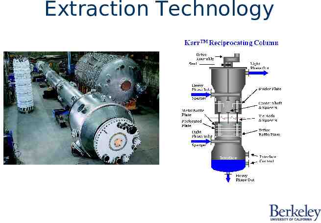
Reciprocating Plate Extractor (Karr) Developed in 1959 Many commercial installations Light liquid out V. High Volumetric Efficiency Vary tray amplitude and frequency Caution at low interfacial tensions Tray movement can clean walls Differential contactor Scale-up to the 0.38 power on diameter Other variations (e.g. VPE) Light liquid in Heavy liquid in Interface Heavy liquid out
Podbielniak Horizontal centrifugal extractor High efficiency Short residence time Minimum inventory Light phase out Light phase in Heavy phase in Heavy phase out
Mixer-Settler Wide range of designs Handle wide range of flow ratios Easy start-up Easy to clean/inspect Batch operations Larger equipment Handles solids Low headroom Occupy much floor space Can add stages Interstage pumping often required High solvent inventory
Hollow Fiber Extractor Solvent Out Feed In Developed in 1980s Modified in 1990s Stage contactor Low organic solvent to aqueous feed ratios Few commercial extraction applications Many commercial gas/liquid applications Solvent In Feed Out
QVF-RZE (agitated cell) RTL Pulsed: packed plate Kühni Karr RDC Packed M/S Sieve Tray Stichlmair (1980)