EE369 POWER SYSTEM ANALYSIS Lecture 6 Development of Transmission

29 Slides1.48 MB
EE369 POWER SYSTEM ANALYSIS Lecture 6 Development of Transmission Line Models Tom Overbye and Ross Baldick 1
Homework HW 5 is Problems 4.1, 4.3, 4.6, 4.26, 4.33, 4.36, 4.38, 4.49, 5.2, 5.4, 5.7, 5.9; due Thursday 9/29. HW 6 is problems 5.14, 5.16, 5.19, 5.26, 5.31, 5.32, 5.33, 5.36; case study questions chapter 5 a, b, c, d, is due Thursday, 10/6. Power plant tour is 10/6. Instead of coming to class, go to UT power plant. Turn in homework at beginning of tour. 2
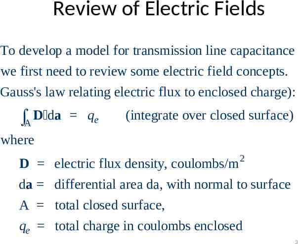
Review of Electric Fields To develop a model for transmission line capacitance we first need to review some electric field concepts. Gauss's law relating electric flux to enclosed charge): A D da qe (integrate over closed surface) where D da A qe electric flux density, coulombs/m 2 differential area da, with normal to surface total closed surface, total charge in coulombs enclosed 3
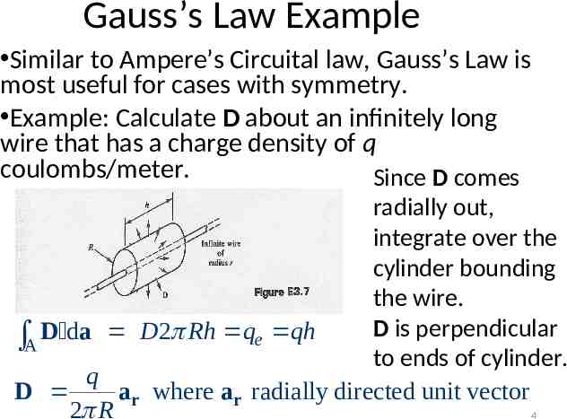
Gauss’s Law Example Similar to Ampere’s Circuital law, Gauss’s Law is most useful for cases with symmetry. Example: Calculate D about an infinitely long wire that has a charge density of q coulombs/meter. Since D comes radially out, integrate over the cylinder bounding the wire. D is perpendicular A D da D 2 Rh qe qh to ends of cylinder. q D ar where ar radially directed unit vector 2 R 4
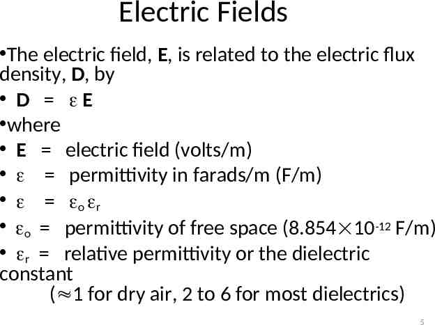
Electric Fields The electric field, E, is related to the electric flux density, D, by D E where E electric field (volts/m) permittivity in farads/m (F/m) o r o permittivity of free space (8.854 10-12 F/m) r relative permittivity or the dielectric constant ( 1 for dry air, 2 to 6 for most dielectrics) 5
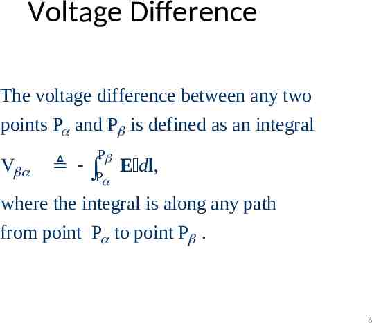
Voltage Difference The voltage difference between any two points P and P is defined as an integral V P E dl, P where the integral is along any path from point P to point P . 6
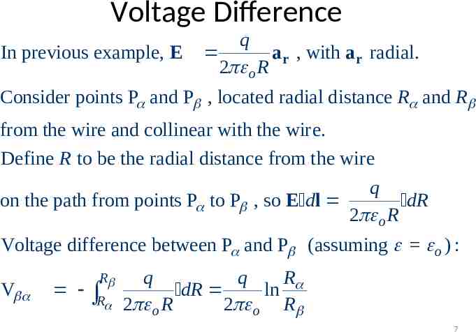
Voltage Difference In previous example, E q ar , with ar radial. 2 o R Consider points P and P , located radial distance R and R from the wire and collinear with the wire. Define R to be the radial distance from the wire q on the path from points P to P , so E dl dR 2 o R Voltage difference between P and P (assuming o ) : V R R R q q dR ln 2 o R 2 o R 7
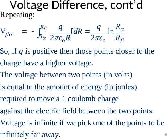
Voltage Difference, cont’d Repeating: V R R R q q dR ln 2 o R 2 o R So, if q is positive then those points closer to the charge have a higher voltage. The voltage between two points (in volts) is equal to the amount of energy (in joules) required to move a 1 coulomb charge against the electric field between the two points. Voltage is infinite if we pick one of the points to be 8 infinitely far away.
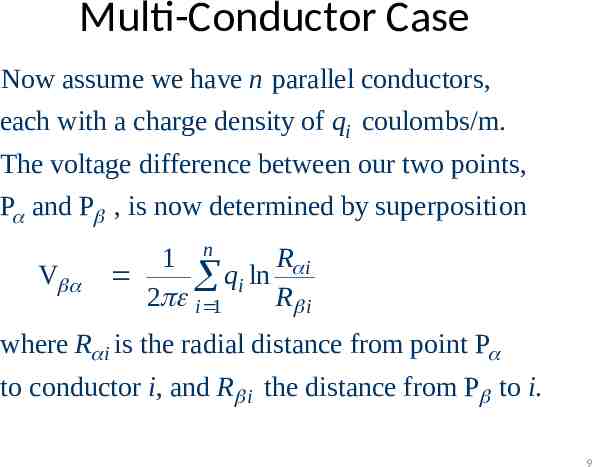
Multi-Conductor Case Now assume we have n parallel conductors, each with a charge density of qi coulombs/m. The voltage difference between our two points, P and P , is now determined by superposition V R i 1 n qi ln 2 i 1 R i where R i is the radial distance from point P to conductor i, and R i the distance from P to i. 9
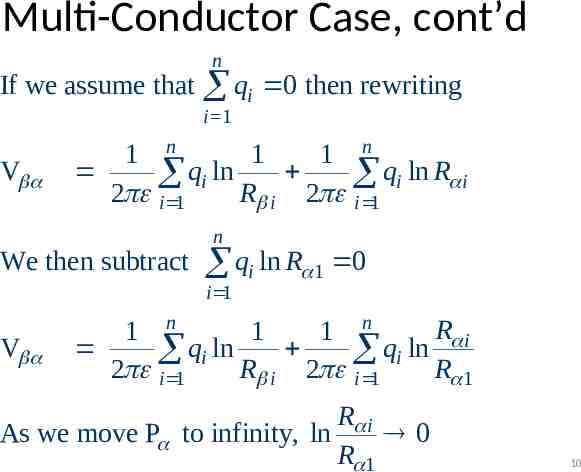
Multi-Conductor Case, cont’d If we assume that n qi 0 then rewriting i 1 V 1 n 1 1 n qi ln qi ln R i 2 i 1 R i 2 i 1 We then subtract n qi ln R 1 0 i 1 V R i 1 n 1 1 n qi ln qi ln 2 i 1 R i 2 i 1 R 1 R i As we move P to infinity, ln 0 R 1 10
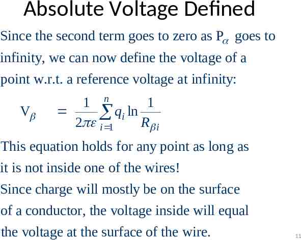
Absolute Voltage Defined Since the second term goes to zero as P goes to infinity, we can now define the voltage of a point w.r.t. a reference voltage at infinity: V 1 n 1 qi ln 2 i 1 R i This equation holds for any point as long as it is not inside one of the wires! Since charge will mostly be on the surface of a conductor, the voltage inside will equal the voltage at the surface of the wire. 11
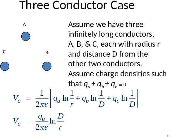
Three Conductor Case Assume we have three infinitely long conductors, A, B, & C, each with radius r B and distance D from the other two conductors. Assume charge densities such that qa qb qc 0 1 1 1 1 Va q ln q ln q ln a b c 2 r D D qa D Va ln 2 r A C 12
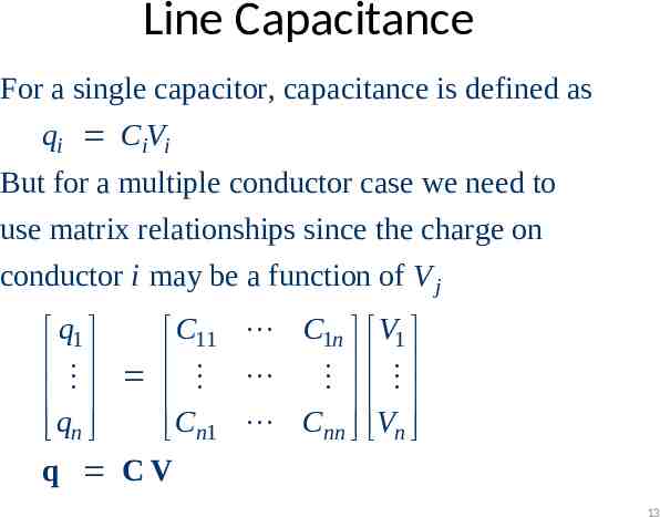
Line Capacitance For a single capacitor, capacitance is defined as qi CiVi But for a multiple conductor case we need to use matrix relationships since the charge on conductor i may be a function of V j q1 C11 C1n V1 qn Cn1 Cnn Vn q CV 13
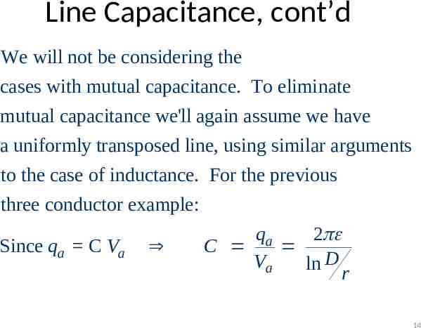
Line Capacitance, cont’d We will not be considering the cases with mutual capacitance. To eliminate mutual capacitance we'll again assume we have a uniformly transposed line, using similar arguments to the case of inductance. For the previous three conductor example: qa 2 Since qa C Va C Va ln D r 14
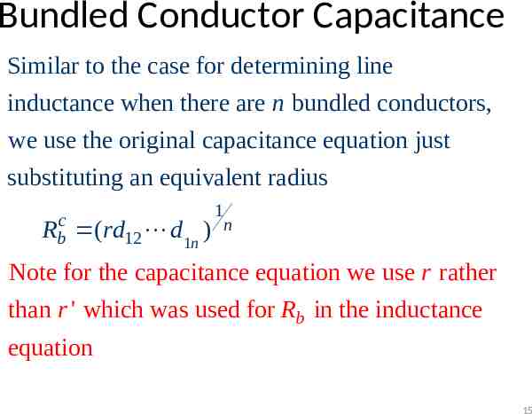
Bundled Conductor Capacitance Similar to the case for determining line inductance when there are n bundled conductors, we use the original capacitance equation just substituting an equivalent radius Rbc (rd12 d1n ) 1 n Note for the capacitance equation we use r rather than r ' which was used for Rb in the inductance equation 15
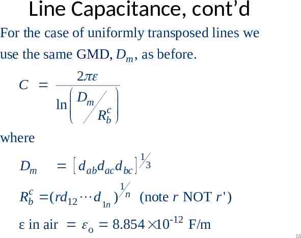
Line Capacitance, cont’d For the case of uniformly transposed lines we use the same GMD, GMR, Dm , as before. 2 C Dm ln c R b where Dm Rbc d ab d ac d bc ( rd12 d 1n ) 1 n 1 3 (note r NOT r ') ε in air o 8.854 10-12 F/m 16
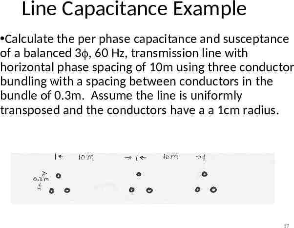
Line Capacitance Example Calculate the per phase capacitance and susceptance of a balanced 3 , 60 Hz, transmission line with horizontal phase spacing of 10m using three conductor bundling with a spacing between conductors in the bundle of 0.3m. Assume the line is uniformly transposed and the conductors have a a 1cm radius. 17
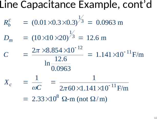
Line Capacitance Example, cont’d Rbc Dm C Xc (0.01 0.3 0.3) (10 10 20) 1 3 1 3 0.0963 m 12.6 m 2 8.854 10 12 11 1.141 10 F/m 12.6 ln 0.0963 1 1 C 2 60 1.141 10 11 F/m 2.33 108 -m (not / m) 18
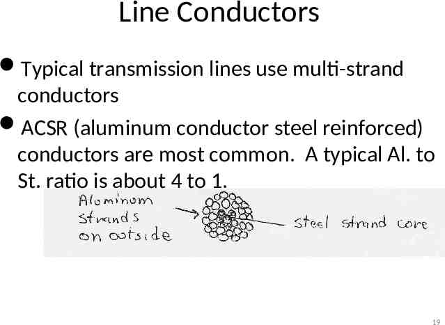
Line Conductors Typical transmission lines use multi-strand conductors ACSR (aluminum conductor steel reinforced) conductors are most common. A typical Al. to St. ratio is about 4 to 1. 19
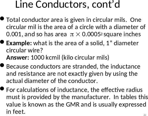
Line Conductors, cont’d Total conductor area is given in circular mils. One circular mil is the area of a circle with a diameter of 0.001, and so has area 0.00052 square inches Example: what is the area of a solid, 1” diameter circular wire? Answer: 1000 kcmil (kilo circular mils) Because conductors are stranded, the inductance and resistance are not exactly given by using the actual diameter of the conductor. For calculations of inductance, the effective radius must is provided by the manufacturer. In tables this value is known as the GMR and is usually expressed in feet. 20
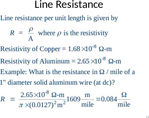
Line Resistance Line resistance per unit length is given by R where is the resistivity A Resistivity of Copper 1.68 10-8 Ω-m Resistivity of Aluminum 2.65 10-8 Ω-m Example: What is the resistance in Ω / mile of a 1" diameter solid aluminum wire (at dc)? -8 2.65 10 Ω-m m R 1609 0.084 2 2 mile mile (0.0127) m 21
Line Resistance, cont’d Because ac current tends to flow towards the surface of a conductor, the resistance of a line at 60 Hz is slightly higher than at dc. Resistivity and hence line resistance increase as conductor temperature increases (changes is about 8% between 25 C and 50 C) Because ACSR conductors are stranded, actual resistance, inductance, and capacitance needs to be determined from tables. 22
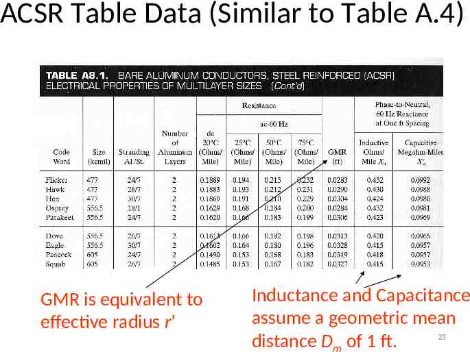
ACSR Table Data (Similar to Table A.4) GMR is equivalent to effective radius r’ Inductance and Capacitance assume a geometric mean 23 distance Dm of 1 ft.
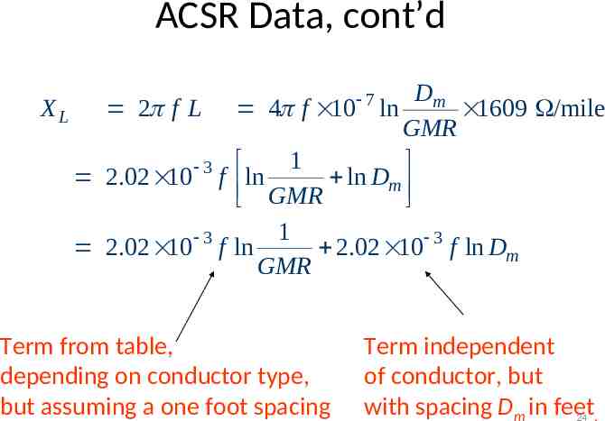
ACSR Data, cont’d Dm X L 2 f L 4 f 10 ln 1609 /mile GMR 1 3 2.02 10 f ln ln Dm GMR 1 3 2.02 10 f ln 2.02 10 3 f ln Dm GMR 7 Term from table, depending on conductor type, but assuming a one foot spacing Term independent of conductor, but with spacing Dm in feet 24 .
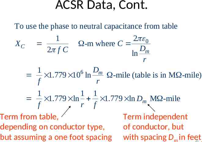
ACSR Data, Cont. To use the phase to neutral capacitance from table 2 0 XC -m where C Dm ln r Dm 1 6 1.779 10 ln -mile (table is in M -mile) f r 1 1 1 1.779 ln 1.779 ln Dm M -mile f r f Term from table, Term independent depending on conductor type, of conductor, but but assuming a one foot spacing with spacing Dm in feet 25 . 1 2 f C
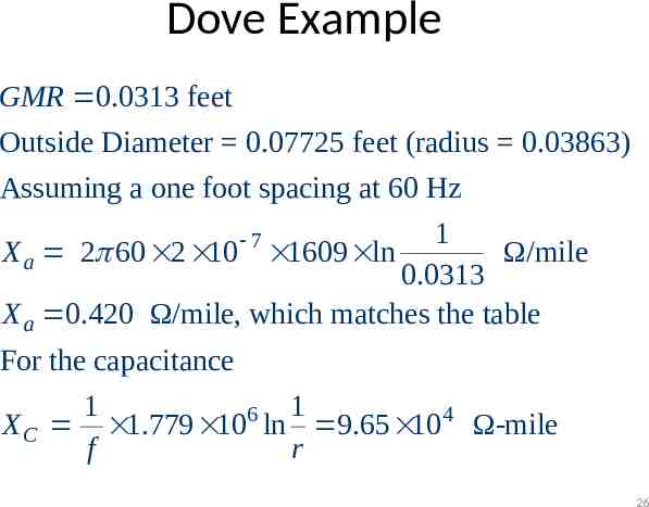
Dove Example GMR 0.0313 feet Outside Diameter 0.07725 feet (radius 0.03863) Assuming a one foot spacing at 60 Hz 1 X a 2 60 2 10 1609 ln Ω/mile 0.0313 X a 0.420 Ω/mile, which matches the table 7 For the capacitance 1 1 6 X C 1.779 10 ln 9.65 104 Ω-mile f r 26
Additional Transmission Topics Multi-circuit lines: Multiple lines often share a common transmission right-of-way. This DOES cause mutual inductance and capacitance, but is often ignored in system analysis. Cables: There are about 3000 miles of underground ac cables in U.S. Cables are primarily used in urban areas. In a cable the conductors are tightly spaced, ( 1ft) with oil impregnated paper commonly used to provide insulation – inductance is lower – capacitance is higher, limiting cable length 27
Additional Transmission topics Ground wires: Transmission lines are usually protected from lightning strikes with a ground wire. This topmost wire (or wires) helps to attenuate the transient voltages/currents that arise during a lighting strike. The ground wire is typically grounded at each pole. Corona discharge: Due to high electric fields around lines, the air molecules become ionized. This causes a crackling sound and may cause the line to glow! 28
Additional Transmission topics Shunt conductance: Usually ignored. A small current may flow through contaminants on insulators. DC Transmission: Because of the large fixed cost necessary to convert ac to dc and then back to ac, dc transmission is only practical for several specialized applications – long distance overhead power transfer ( 400 miles) – long cable power transfer such as underwater – providing an asynchronous means of joining different power systems (such as the Eastern and ERCOT grids). 29