Core Overview, Bending and Torsion Testing Snehal Shetye, Rob Mauck


20 Slides4.12 MB
Core Overview, Bending and Torsion Testing Snehal Shetye, Rob Mauck
Biomechanics Core – How we operate Key players: Rob Mauck (Director) – Snehal Shetye (Technical Director) – Ashley Rodriguez (Research Specialist) https://www.med.upenn.edu/pcmd/biomechanics.html Submit project request form In reality most PIs just directly contact Rob Rob and Snehal sit down with client group to review proposed project, feasibility, approach. Core user has a choice: Self-service (you get trained and then test yourself) Fee for service (Snehal and Ashley do the project for you) After getting trained, you get access to Google Calendar for the particular equipment Remember to cite us in your manuscript: Grant number is P30 AR069619
Available Equipment Instron 5542 (x2) Instron 5543 Instron 5848 (x2) Instron ElectroPuls Instron 8874 Compression MicroTester Freezing Stage Microtome Polarizing Scope Dynamic Cross-Polarized Light Imaging Setup GisMO (cross-sectional area measurement device) 3D Printer Software MATLAB, GraphPad, SPSS, Abaqus, Trellis, Rhino 3D, QCapture Pro Milling Machine, Mini-Lathe, Vertical and Horizontal Bandsaws, Soldering and Electrical Equipment
Signing up and Etiquette Signup on Google Calendar: PCMD: PI Last Name : your pennkey – Note: McKay does get first dibs on equipment usage – Generally, you can only access equipment between the hours of 9-5pm We can bend the rules for special circumstances – All hardware is shared among all users, including McKay, so usually allocate extra time for find your fixtures! Format is important We summarize quarterly usage and send invoices to PIs Current PCMD Biomechanics core discount: 90% If there is a scheduling conflict Talk to Snehal or email the other person (pennkey is on calendar signup) and ask nicely Accessing Snehal Don’t hesitate to contact me anytime (I am at McKay from 6:30am to 4pm) Do remember I have two jobs: Soslowsky Lab and PCMD Biomechanics Core
3-point Bending Load (F) 3-point test
Shear and Moment Diagram Maximum moment at center point of beam
4-point Bending Load 4-point test
Shear and Moment Diagram Maximum moment spans distance between top actuators
Parameters Compression 𝑦 Maximum Flexural Stress Tension – Here, is 2nd moment of inertia, moment applied at middle of specimen, distance from center of specimen to convex surface Elastic Modulus (for 3-point bending) (for 4-point bending) – Here, is deflection at max. force, is length between bottom supports, and is max. force Bending Stiffness Slope of linear region from force-displacement curve
How do we calculate ? Laws of static mechanics: Sum of all forces Sum of all moments at a single point – These two equations will resolve the unknown reaction forces at the bottom supports – Moment at any point can now be calculated 3-point Bending: 4-point Bending
How do we calculate ? This is difficult for biological specimens For bone Obtain uCT scans of mid-shaft We have a custom MATLAB code that calculates for any chosen axis (Bending Buddy) This code also estimates by fitting circle to bone cross-section and obtaining equivalent radius
Stuff to Consider Measure length of all your samples to determine proper support spacing 3-point bending not recommended for fractured bone 4-point bending is generally always recommended over 3-point unless tissue is too small Torsion tests work well for fractured specimens Most ideal to test all samples on same day (day-to-day variation in test setup can influence results) Keep orientation constant for all samples! Find a stable orientation such that bone does not rotate while being loaded
Example 4-point bend setup
Failure modes in bone
When to use torsion tests? 3-pt or 4-pt bend tests work well for intact specimens Fractured samples 3-pt test will cause significant stress concentrations at the contact point – Usually that is where the fracture/callus is – Definitely not recommended 4-pt test loading points should span the healing site – Difficult to achieve on mouse femora/tibiae – Cannot control size and location of fracture callus Torsion – Usually have unobstructed access to epiphysis – Only test that evaluates the entire free length of the bone – Does need 6-dof fixation at the termini – Takes longer for prep and setup Load (F) Load
Torsion testing
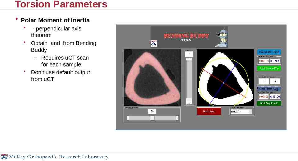
Torsion Parameters Polar Moment of Inertia - perpendicular axis theorem Obtain and from Bending Buddy – Requires uCT scan for each sample Don’t use default output from uCT
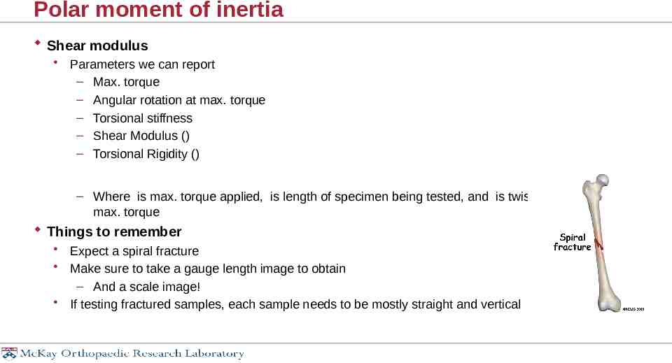
Polar moment of inertia Shear modulus Parameters we can report – Max. torque – Angular rotation at max. torque – Torsional stiffness – Shear Modulus () – Torsional Rigidity () – Where is max. torque applied, is length of specimen being tested, and is twist (in radians) at max. torque Things to remember Expect a spiral fracture Make sure to take a gauge length image to obtain – And a scale image! If testing fractured samples, each sample needs to be mostly straight and vertical
Torsion Testing
Questions?