Chapter 7 System Models Ian Sommerville 2000 Software Engineering, 6th


44 Slides442.00 KB
Chapter 7 System Models Ian Sommerville 2000 Software Engineering, 6th edition. Chapter 7 Slide 1
System models Abstract descriptions of systems whose requirements are being analysed Ian Sommerville 2000 Software Engineering, 6th edition. Chapter 7 Slide 2
Objectives To explain why the context of a system should be modelled as part of the RE process To describe behavioural modelling, data modelling and object modelling To introduce some of the notations used in the Unified Modeling Language (UML) To show how CASE workbenches support system modelling Ian Sommerville 2000 Software Engineering, 6th edition. Chapter 7 Slide 3
Topics covered Context models Behavioural models Data models Object models CASE workbenches Ian Sommerville 2000 Software Engineering, 6th edition. Chapter 7 Slide 4
System modelling System modelling helps the analyst to understand the functionality of the system and models are used to communicate with customers Different models present the system from different perspectives External perspective showing the system’s context or environment Behavioural perspective showing the behaviour of the system Structural perspective showing the system or data architecture Ian Sommerville 2000 Software Engineering, 6th edition. Chapter 7 Slide 5
Structured methods Structured methods incorporate system modelling as an inherent part of the method Methods define a set of models, a process for deriving these models and rules and guidelines that should apply to the models CASE tools support system modelling as part of a structured method Ian Sommerville 2000 Software Engineering, 6th edition. Chapter 7 Slide 6
Method weaknesses They do not model non-functional system requirements They do not usually include information about whether a method is appropriate for a given problem The may produce too much documentation The system models are sometimes too detailed and difficult for users to understand Ian Sommerville 2000 Software Engineering, 6th edition. Chapter 7 Slide 7
Model types Data processing model showing how the data is processed at different stages Composition model showing how entities are composed of other entities Architectural model showing principal sub-systems Classification model showing how entities have common characteristics Stimulus/response model showing the system’s reaction to events Ian Sommerville 2000 Software Engineering, 6th edition. Chapter 7 Slide 8
Context models Context models are used to illustrate the boundaries of a system Social and organisational concerns may affect the decision on where to position system boundaries Architectural models show the a system and its relationship with other systems Ian Sommerville 2000 Software Engineering, 6th edition. Chapter 7 Slide 9
The context of an ATM system Security system Branch accounting system Account database Auto-teller system Branch counter system Usage database Maintenance system Ian Sommerville 2000 Software Engineering, 6th edition. Chapter 7 Slide 10
Process models Process models show the overall process and the processes that are supported by the system Data flow models may be used to show the processes and the flow of information from one process to another Ian Sommerville 2000 Software Engineering, 6th edition. Chapter 7 Slide 11
Equipment procurement process Delivery note Specify equipment requir ed Equipment spec. Validate specification Equipment spec. Supplier database Checked spec. Supplier list Find suppliers Accept delivery of equipment Get cost estimates Spec. supplier estima te Choose supplier Order notification Order details Blank order form Place equipment order Checked and signed order form Delivery note Check delivered items Installation instructions Install equipment Installation acceptance Accept delivered equipment Equipment details Equipment database Ian Sommerville 2000 Software Engineering, 6th edition. Chapter 7 Slide 12
Behavioural models Behavioural models are used to describe the overall behaviour of a system Two types of behavioural model are shown here Data processing models that show how data is processed as it moves through the system State machine models that show the systems response to events Both of these models are required for a description of the system’s behaviour Ian Sommerville 2000 Software Engineering, 6th edition. Chapter 7 Slide 13
Data-processing models Data flow diagrams are used to model the system’s data processing These show the processing steps as data flows through a system Intrinsic part of many analysis methods Simple and intuitive notation that customers can understand Show end-to-end processing of data Ian Sommerville 2000 Software Engineering, 6th edition. Chapter 7 Slide 14
Order processing DFD Or der details blank order form Completed order form Complete order form Signed order form Valida te order Signed order form Checked and signed order order notification Send to supplier Record order Order details Signed order form Adjust available budget Order amount account details Orders file Ian Sommerville 2000 Software Engineering, 6th edition. Chapter 7 Budget file Slide 15
Data flow diagrams DFDs model the system from a functional perspective Tracking and documenting how the data associated with a process is helpful to develop an overall understanding of the system Data flow diagrams may also be used in showing the data exchange between a system and other systems in its environment Ian Sommerville 2000 Software Engineering, 6th edition. Chapter 7 Slide 16
CASE toolset DFD Input design Valid design Design editor Referenced designs Design database Ian Sommerville 2000 Checked design Design cross checker and Design analysis Design analyser Checked design Code skeleton generator Software Engineering, 6th edition. Chapter 7 User report Report generator Output code Design database Slide 17
State machine models These model the behaviour of the system in response to external and internal events They show the system’s responses to stimuli so are often used for modelling real-time systems State machine models show system states as nodes and events as arcs between these nodes. When an event occurs, the system moves from one state to another Statecharts are an integral part of the UML Ian Sommerville 2000 Software Engineering, 6th edition. Chapter 7 Slide 18
Microwave oven model Full power Full power do: set power 600 Timer Waiting do: display time Half power Number Full power Half power Door closed Timer Door open Half power do: set power 300 Operation do: operate oven Set time do: get number exit: set time Door closed Cancel Start Enabled do: display 'Ready' Door open Waiting do: display time Disabled do: display 'Waiting' Ian Sommerville 2000 Software Engineering, 6th edition. Chapter 7 Slide 19
Microwave oven state description Ian Sommerville 2000 Software Engineering, 6th edition. Chapter 7 Slide 20
Microwave oven stimuli Ian Sommerville 2000 Software Engineering, 6th edition. Chapter 7 Slide 21
Statecharts Allow the decomposition of a model into submodels (see following slide) A brief description of the actions is included following the ‘do’ in each state Can be complemented by tables describing the states and the stimuli Ian Sommerville 2000 Software Engineering, 6th edition. Chapter 7 Slide 22
Microwave oven operation Operation Checking do: check status Turntable fault Time Cook do: run generator OK Emitter fault Timeout Done do: buzzer on for 5 secs. Alarm do: display event Door open Disabled Ian Sommerville 2000 Cancel Waiting Software Engineering, 6th edition. Chapter 7 Slide 23
Semantic data models Used to describe the logical structure of data processed by the system Entity-relation-attribute model sets out the entities in the system, the relationships between these entities and the entity attributes Widely used in database design. Can readily be implemented using relational databases No specific notation provided in the UML but objects and associations can be used Ian Sommerville 2000 Software Engineering, 6th edition. Chapter 7 Slide 24
Software design semantic model Design 1 name description C-date M-date is-a has-nodes 1 has-links 1 n n 1 Node has-links 1 name type 2 Link n 1 links name type 1 1 has-labels has-labels Label n Ian Sommerville 2000 name text icon n Software Engineering, 6th edition. Chapter 7 Slide 25
Data dictionaries Data dictionaries are lists of all of the names used in the system models. Descriptions of the entities, relationships and attributes are also included Advantages Support name management and avoid duplication Store of organisational knowledge linking analysis, design and implementation Many CASE workbenches support data dictionaries Ian Sommerville 2000 Software Engineering, 6th edition. Chapter 7 Slide 26
Data dictionary entries Ian Sommerville 2000 Software Engineering, 6th edition. Chapter 7 Slide 27
Object models Object models describe the system in terms of object classes An object class is an abstraction over a set of objects with common attributes and the services (operations) provided by each object Various object models may be produced Inheritance models Aggregation models Interaction models Ian Sommerville 2000 Software Engineering, 6th edition. Chapter 7 Slide 28
Object models Natural ways of reflecting the real-world entities manipulated by the system More abstract entities are more difficult to model using this approach Object class identification is recognised as a difficult process requiring a deep understanding of the application domain Object classes reflecting domain entities are reusable across systems Ian Sommerville 2000 Software Engineering, 6th edition. Chapter 7 Slide 29
Inheritance models Organise the domain object classes into a hierarchy Classes at the top of the hierarchy reflect the common features of all classes Object classes inherit their attributes and services from one or more super-classes. these may then be specialised as necessary Class hierarchy design is a difficult process if duplication in different branches is to be avoided Ian Sommerville 2000 Software Engineering, 6th edition. Chapter 7 Slide 30
The Unified Modeling Language Devised by the developers of widely used object-oriented analysis and design methods Has become an effective standard for object-oriented modelling Notation Object classes are rectangles with the name at the top, attributes in the middle section and operations in the bottom section Relationships between object classes (known as associations) are shown as lines linking objects Inheritance is referred to as generalisation and is shown ‘upwards’ rather than ‘downwards’ in a hierarchy Ian Sommerville 2000 Software Engineering, 6th edition. Chapter 7 Slide 31
Library item Library class hierarchy Catalogue number Acquisition date Cost Type Status Number of copies Acquire () Catalogue () Dispose () Issue () Return () Published item Recorded item Title Medium Title Publisher Book Author Edition Publication date ISBN Magazine Year Issue Film Director Date of release Distributor Computer program Version Platform
User class hierarchy Libr ary user Name Address Phone Registration # Register () De-r egister () Reader Borrower Items on loan Max. loans Affiliation Staff Department Department phone Student Major subject Home address
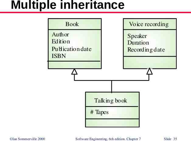
Multiple inheritance Rather than inheriting the attributes and services from a single parent class, a system which supports multiple inheritance allows object classes to inherit from several super-classes Can lead to semantic conflicts where attributes/services with the same name in different super-classes have different semantics Makes class hierarchy reorganisation more complex Ian Sommerville 2000 Software Engineering, 6th edition. Chapter 7 Slide 34
Multiple inheritance Book Voice recording Author Edition Publication date ISBN Speaker Duration Recording date Talking book # Tapes Ian Sommerville 2000 Software Engineering, 6th edition. Chapter 7 Slide 35
Object aggregation Aggregation model shows how classes which are collections are composed of other classes Similar to the part-of relationship in semantic data models Ian Sommerville 2000 Software Engineering, 6th edition. Chapter 7 Slide 36
Object aggregation Study pack Course title Number Year Instructor OHP slides Assignment Slides Credits Exercises #Problems Description Ian Sommerville 2000 Lectur e notes Text Videotape Tape ids. Solutions Text Diagrams Software Engineering, 6th edition. Chapter 7 Slide 37
Object behaviour modelling A behavioural model shows the interactions between objects to produce some particular system behaviour that is specified as a use-case Sequence diagrams (or collaboration diagrams) in the UML are used to model interaction between objects Ian Sommerville 2000 Software Engineering, 6th edition. Chapter 7 Slide 38
Issue of electronic items Ecat: Catalog :Library Item Lib1: NetServer :Library User Lookup Display Issue Issue licence Accept licence Compress Deliver Ian Sommerville 2000 Software Engineering, 6th edition. Chapter 7 Slide 39
CASE workbenches A coherent set of tools that is designed to support related software process activities such as analysis, design or testing Analysis and design workbenches support system modelling during both requirements engineering and system design These workbenches may support a specific design method or may provide support for a creating several different types of system model Ian Sommerville 2000 Software Engineering, 6th edition. Chapter 7 Slide 40
An analysis and design workbench Data dictionary Structured diagramming tools Report generation facilities Code generator Central information repository Query language facilities Forms creation tools Design, analysis and checking tools Import/export facilities Ian Sommerville 2000 Software Engineering, 6th edition. Chapter 7 Slide 41
Analysis workbench components Diagram editors Model analysis and checking tools Repository and associated query language Data dictionary Report definition and generation tools Forms definition tools Import/export translators Code generation tools Ian Sommerville 2000 Software Engineering, 6th edition. Chapter 7 Slide 42
Key points A model is an abstract system view. Complementary types of model provide different system information Context models show the position of a system in its environment with other systems and processes Data flow models may be used to model the data processing in a system State machine models model the system’s behaviour in response to internal or external events Ian Sommerville 2000 Software Engineering, 6th edition. Chapter 7 Slide 43
Key points Semantic data models describe the logical structure of data which is imported to or exported by the systems Object models describe logical system entities, their classification and aggregation Object models describe the logical system entities and their classification and aggregation CASE workbenches support the development of system models Ian Sommerville 2000 Software Engineering, 6th edition. Chapter 7 Slide 44