Chapter 5 – System Modeling Lecture 2 Chapter 5 System modeling 1
45 Slides548.50 KB
Chapter 5 – System Modeling Lecture 2 Chapter 5 System modeling 1
3. Structural Models Structural models of software display the organization of a system in terms of the components and their relationships. Structural models may be static models, which show the structure of the system design, or dynamic models, which show the organization of the system when it is executing. Structural models are created when discussing and designing the system architecture. Chapter 5 System modeling 2
Class Diagrams Class diagrams are used when developing an object-oriented system model to show the classes in a system and the associations between these classes. An association is a link between classes that indicates that there is some relationship between these classes. When you are developing models during the early stages of the software engineering process, objects represent something in the real world, such as a patient, a prescription, doctor, a device, etc. We have spoken in terms of 'nouns' or 'things.' Chapter 5 System modeling 3
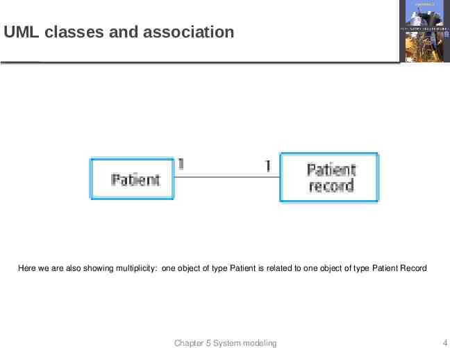
UML classes and association Here we are also showing multiplicity: one object of type Patient is related to one object of type Patient Record Chapter 5 System modeling 4
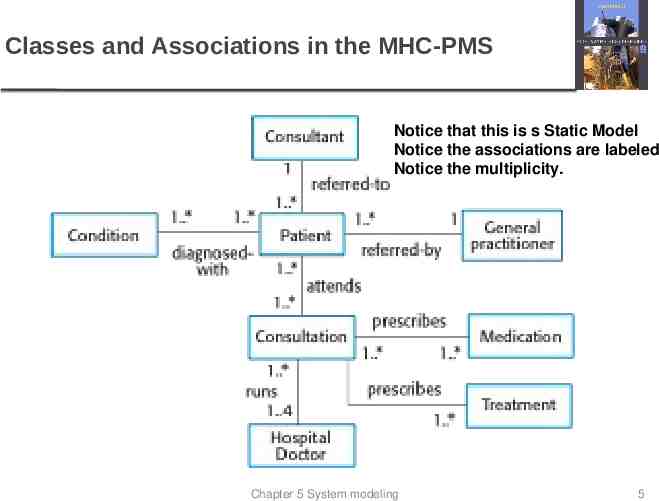
Classes and Associations in the MHC-PMS Notice that this is s Static Model Notice the associations are labeled Notice the multiplicity. Chapter 5 System modeling 5
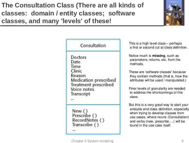
The Consultation Class (There are all kinds of classes: domain / entity classes; software classes, and many 'levels' of these! This is a high level class – perhaps a first or second cut at class definition. Notice much is missing, such as parameters, returns, etc. from the methods. These are ‘software classes’ because they contain methods (that is, how the attributes will be used / manipulated.) Finer levels of granularity are needed to address the shortcomings of this class. But this is a very good way to start your analysis and class definition, especially when trying to develop classes from use cases, where nouns (Consultation) and verbs (new, prescribe .) will be found in the use case itself. Chapter 5 System modeling 6
Generalization Generalization is an everyday technique that we use to Rather than learn the detailed characteristics of every entity that we experience, we place these entities in more general classes (animals, cars, houses, etc.) and learn the characteristics of these classes. This allows us to infer that different members of these classes have some common characteristics e.g. squirrels and rats are rodents. In programming, we refer to this as 'inheritance.' Base class and derived classes, or super class and derived class. parent and child. many terms for capturing these important relationships. Chapter 5 System modeling 7
Generalization In modeling systems, it is often useful to examine the classes in a system to see if there is scope for generalization. In object-oriented languages, such as Java, generalization is implemented using the class inheritance mechanisms built into the language. In a generalization, the attributes and operations associated with higher-level classes are also associated with (inherited by) the lower-level classes. The lower-level classes are subclasses inherit the attributes and operations from their superclasses. These lower-level classes then add more specific attributes and operations. Chapter 5 System modeling 8
Relationships: Generalization A relationship among classes where one class shares the structure and/or behavior of one or more classes Defines a hierarchy of abstractions in which a subclass inherits from one or more superclasses Single inheritance Multiple inheritance Generalization is an “is-a-kind of” relationship, or simply, “is a” relationship.
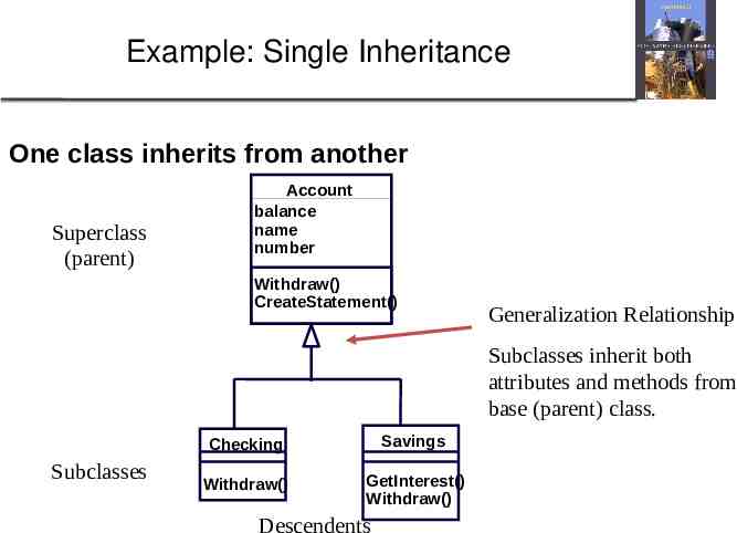
Example: Single Inheritance One class inherits from another Superclass (parent) Account balance name number Withdraw() CreateStatement() Generalization Relationship Subclasses inherit both attributes and methods from base (parent) class. Subclasses Checking Savings Withdraw() GetInterest() Withdraw() Descendents
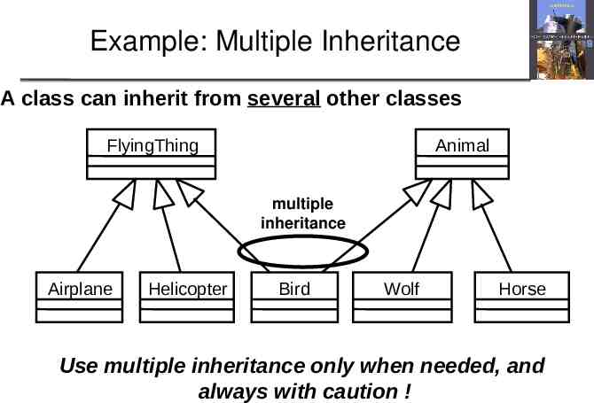
Example: Multiple Inheritance A class can inherit from several other classes FlyingThing Animal multiple inheritance Airplane Helicopter Bird Wolf Horse Use multiple inheritance only when needed, and always with caution !
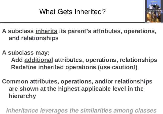
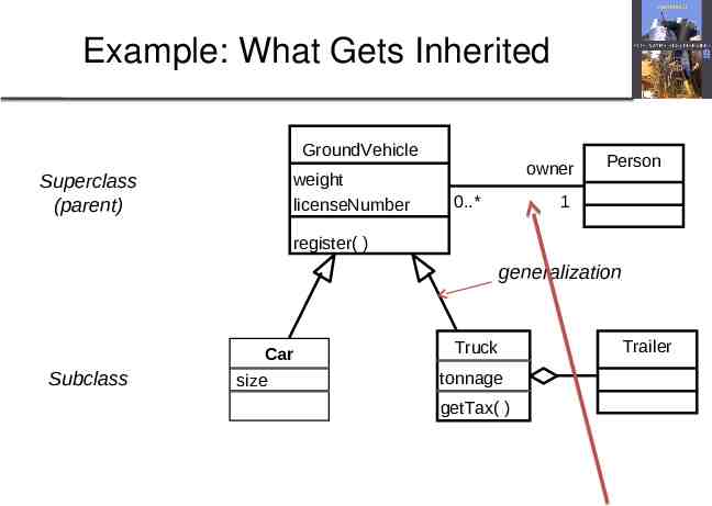
What Gets Inherited? A subclass inherits its parent’s attributes, operations, and relationships A subclass may: Add additional attributes, operations, relationships Redefine inherited operations (use caution!) Common attributes, operations, and/or relationships are shown at the highest applicable level in the hierarchy Inheritance leverages the similarities among classes
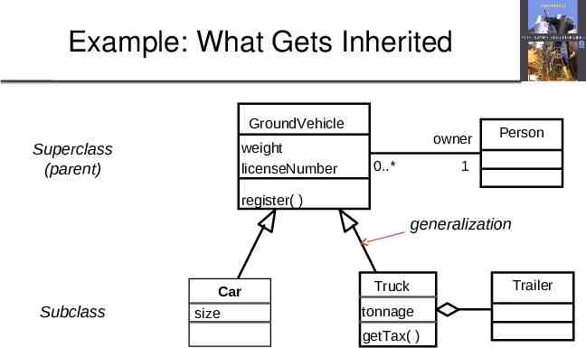
Example: What Gets Inherited GroundVehicle Superclass (parent) weight licenseNumber owner 0.* Person 1 register( ) generalization Subclass Car size Truck tonnage getTax( ) Trailer
Object class aggregation models An aggregation model shows how classes that are collections are composed of other classes. Aggregation models are similar to the part-of relationship in semantic data models. Chapter 5 System modeling 14
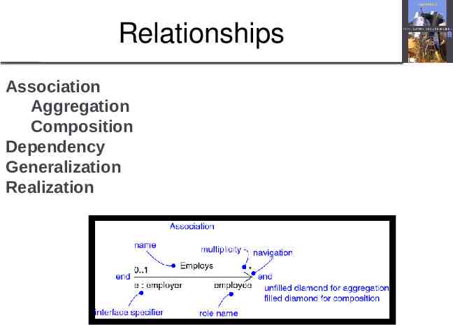
Relationships Association Aggregation Composition Dependency Generalization Realization
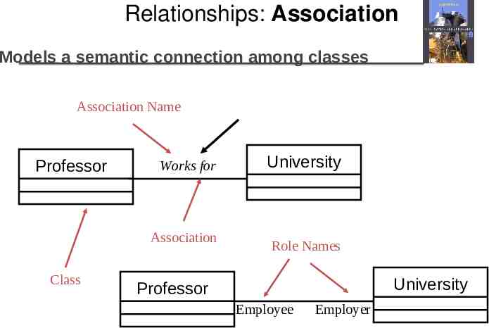
Relationships: Association Models a semantic connection among classes Association Name Professor Works for Association Class University Role Names University Professor Employee Employer
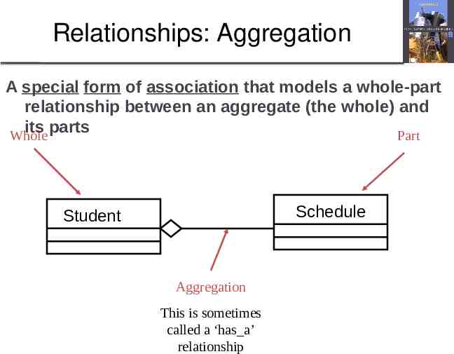
Relationships: Aggregation A special form of association that models a whole-part relationship between an aggregate (the whole) and its parts Whole Part Schedule Student Aggregation This is sometimes called a ‘has a’ relationship
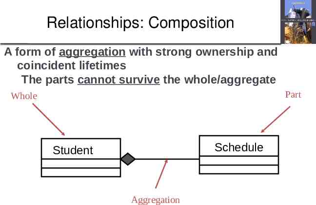
Relationships: Composition A form of aggregation with strong ownership and coincident lifetimes The parts cannot survive the whole/aggregate Part Whole Schedule Student Aggregation
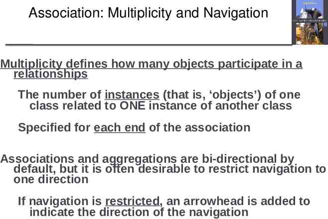
Association: Multiplicity and Navigation Multiplicity defines how many objects participate in a relationships The number of instances (that is, ‘objects’) of one class related to ONE instance of another class Specified for each end of the association Associations and aggregations are bi-directional by default, but it is often desirable to restrict navigation to one direction If navigation is restricted, an arrowhead is added to indicate the direction of the navigation
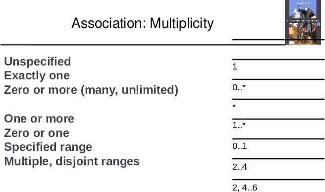
Association: Multiplicity Unspecified Exactly one Zero or more (many, unlimited) One or more Zero or one Specified range Multiple, disjoint ranges 1 0.* * 1.* 0.1 2.4 2, 4.6
Example: What Gets Inherited GroundVehicle Superclass (parent) weight licenseNumber owner 0.* Person 1 register( ) generalization Subclass Car size Truck tonnage getTax( ) Trailer
Key points Structural models show the organization and architecture of a system. Class diagrams are used to define the static structure of classes in a system and their associations. Chapter 5 System modeling 22
4. Behavioral Models Behavioral models are models of the dynamic behavior of a system as it is executing. They show what happens or what is supposed to happen when a system responds to a stimulus from its environment. You can think of these stimuli as being of two types: A. Data Some data arrives that has to be processed by the system. B. Events Some event happens that triggers system processing. Events may have associated data, although this is not always the case. Chapter 5 System modeling 23
A. Data-driven Modeling Many business systems are data-processing systems that are primarily driven by data. They are controlled by the data input to the system, with relatively little external event processing. Data-driven models show the sequence of actions involved in processing input data and generating an associated output. They are particularly useful during the analysis of requirements as they can be used to show end-to-end processing in a system. Chapter 5 System modeling 24
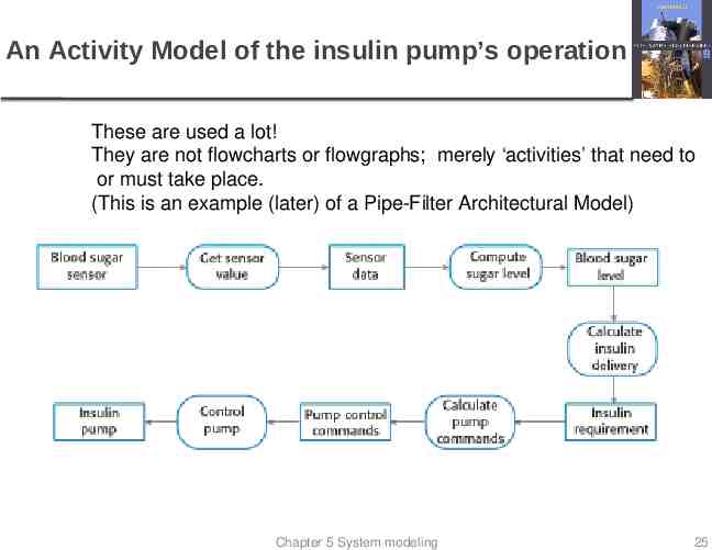
An Activity Model of the insulin pump’s operation These are used a lot! They are not flowcharts or flowgraphs; merely ‘activities’ that need to or must take place. (This is an example (later) of a Pipe-Filter Architectural Model) Chapter 5 System modeling 25
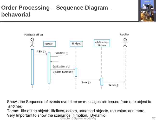
Order Processing – Sequence Diagram behavorial Shows the Sequence of events over time as messages are issued from one object to another. Terms: life of the object; lifelines, actors, unnamed objects, recursion, and more. Very Important to show the scenarios in motion. Dynamic! Chapter 5 System modeling 26
B. Event-Driven Modeling Real-time systems are often event-driven, with minimal data processing. For example, a landline phone switching system responds to events such as ‘receiver off hook’ by generating a dial tone. Event-driven modeling shows how a system responds to external and internal events. It is based on the assumption that a system has a finite number of states and that events (stimuli) may cause a transition from one state to another. Chapter 5 System modeling 27
State Machine Models These model the behaviour of the system in response to external and internal events. They show the system’s responses to stimuli so are often used for modeling real-time systems. State machine models show system states as nodes and events as arcs between these nodes. When an event occurs, the system moves from one state to another. Statecharts are an integral part of the UML and are used to represent state machine models. Chapter 5 System modeling 28
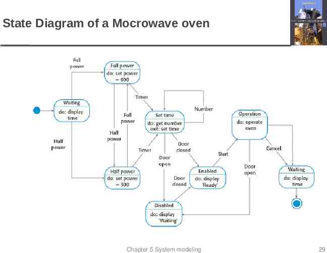
State Diagram of a Mocrowave oven Chapter 5 System modeling 29
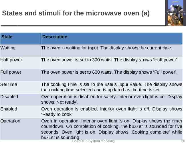
States and stimuli for the microwave oven (a) State Description Waiting The oven is waiting for input. The display shows the current time. Half power The oven power is set to 300 watts. The display shows ‘Half power’. Full power The oven power is set to 600 watts. The display shows ‘Full power’. Set time The cooking time is set to the user’s input value. The display shows the cooking time selected and is updated as the time is set. Oven operation is disabled for safety. Interior oven light is on. Display shows ‘Not ready’. Oven operation is enabled. Interior oven light is off. Display shows ‘Ready to cook’. Oven in operation. Interior oven light is on. Display shows the timer countdown. On completion of cooking, the buzzer is sounded for five seconds. Oven light is on. Display shows ‘Cooking complete’ while buzzer is sounding. Disabled Enabled Operation Chapter 5 System modeling 30
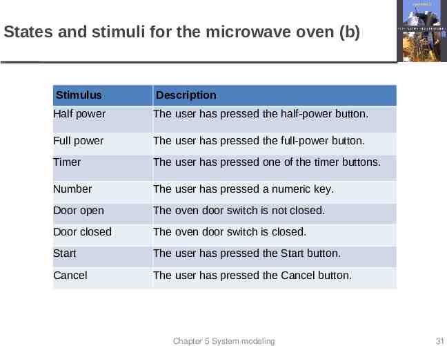
States and stimuli for the microwave oven (b) Stimulus Description Half power The user has pressed the half-power button. Full power The user has pressed the full-power button. Timer The user has pressed one of the timer buttons. Number The user has pressed a numeric key. Door open The oven door switch is not closed. Door closed The oven door switch is closed. Start The user has pressed the Start button. Cancel The user has pressed the Cancel button. Chapter 5 System modeling 31
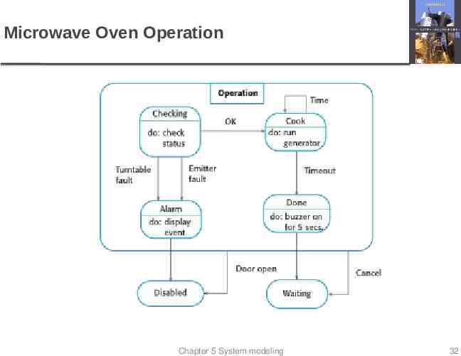
Microwave Oven Operation Chapter 5 System modeling 32
5. Model-Driven Engineering Model-driven engineering (MDE) is an approach to software development where models rather than programs are the principal outputs of the development process. Programs execute on a hardware/software platform are generated automatically from the models. Proponents of MDE argue that this raises the level of abstraction in software engineering so that engineers no longer have to be concerned with programming language details or the specifics of execution platforms. Chapter 5 System modeling 33
Usage of Model-Driven Engineering Model-driven engineering is still at an early stage of development, and it is unclear whether or not it will have a significant effect on software engineering practice. Pros Allows systems to be considered at higher levels of abstraction Generating code automatically means that it is cheaper to adapt systems to new platforms. Cons Models for abstraction and not necessarily right for implementation. Savings from generating code may be outweighed by the costs of developing translators for new platforms. Chapter 5 System modeling 34
Model driven architecture Model-driven architecture (MDA) was the precursor of more general model-driven engineering MDA is a model-focused approach to software design and implementation that uses a subset of UML models to describe a system. Models at different levels of abstraction are created. From a high-level, platform independent model, it is possible, in principle, to generate a working program without manual intervention. Chapter 5 System modeling 35
Examples IEF Information Engineering Facility Rational Rose Others Chapter 5 System modeling 36
Key points Behavioral models are used to describe the dynamic behavior of an executing system. This behavior can be modeled from the perspective of the data processed by the system, or by the events that stimulate responses from a system. Activity diagrams may be used to model the processing of data, where each activity represents one process step. State diagrams are used to model a system’s behavior in response to internal or external events. Model-driven engineering is an approach to software development in which a system is represented as a set of models that can be automatically transformed to executable code. Chapter 5 System modeling 37
On Your Own Good Stuff. Be sure to read through this casually Chapter 5 System modeling 38
Types of model A computation independent model (CIM) These model the important domain abstractions used in a system. CIMs are sometimes called domain models. A platform independent model (PIM) These model the operation of the system without reference to its implementation. The PIM is usually described using UML models that show the static system structure and how it responds to external and internal events. Platform specific models (PSM) These are transformations of the platform-independent model with a separate PSM for each application platform. In principle, there may be layers of PSM, with each layer adding some platform-specific detail. Chapter 5 System modeling 39
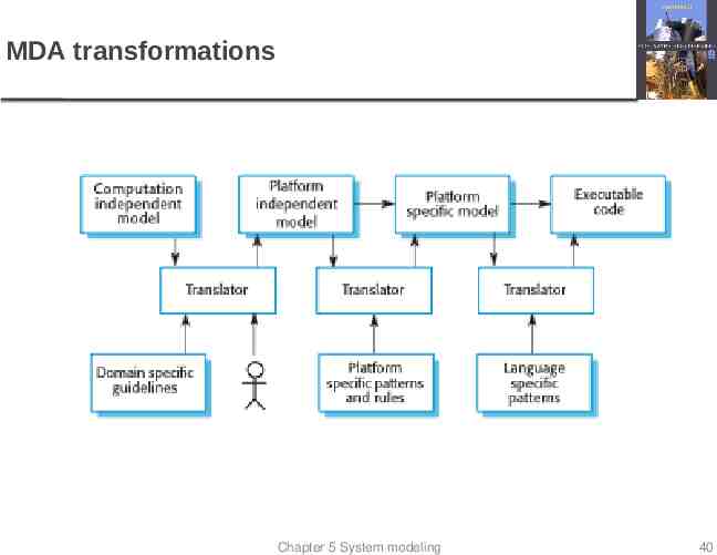
MDA transformations Chapter 5 System modeling 40
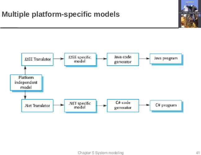
Multiple platform-specific models Chapter 5 System modeling 41
Agile methods and MDA The developers of MDA claim that it is intended to support an iterative approach to development and so can be used within agile methods. The notion of extensive up-front modeling contradicts the fundamental ideas in the agile manifesto and I suspect that few agile developers feel comfortable with modeldriven engineering. If transformations can be completely automated and a complete program generated from a PIM, then, in principle, MDA could be used in an agile development process as no separate coding would be required. Chapter 5 System modeling 42
Executable UML The fundamental notion behind model-driven engineering is that completely automated transformation of models to code should be possible. This is possible using a subset of UML 2, called Executable UML or xUML. Chapter 5 System modeling 43
Features of executable UML To create an executable subset of UML, the number of model types has therefore been dramatically reduced to these 3 key types: Domain models that identify the principal concerns in a system. They are defined using UML class diagrams and include objects, attributes and associations. Class models in which classes are defined, along with their attributes and operations. State models in which a state diagram is associated with each class and is used to describe the life cycle of the class. The dynamic behavior of the system may be specified declaratively using the object constraint language (OCL), or may be expressed using UML’s action language. Chapter 5 System modeling 44
Key points Behavioral models are used to describe the dynamic behavior of an executing system. This behavior can be modeled from the perspective of the data processed by the system, or by the events that stimulate responses from a system. Activity diagrams may be used to model the processing of data, where each activity represents one process step. State diagrams are used to model a system’s behavior in response to internal or external events. Model-driven engineering is an approach to software development in which a system is represented as a set of models that can be automatically transformed to executable code. Chapter 5 System modeling 45