Antenna Design For Wireless Products Kerry Greer Vice President
37 Slides1.66 MB
Antenna Design For Wireless Products Kerry Greer Vice President of Engineering SkyCross Inc. February 25, 2002 2002 SkyCross. All Rights Reserved.
Topics Antenna Evolution Changing Wireless Marketplace Issues Driving Antenna Design Antenna Physics Antenna Performance Specifications External Antennas Embedded Antennas Advanced Wireless Device Antenna Concepts leading leadingwireless wirelessinnovation innovation Page Page22 COMPANY 2002 CONFIDENTIAL SkyCross. All Rights Reserved.
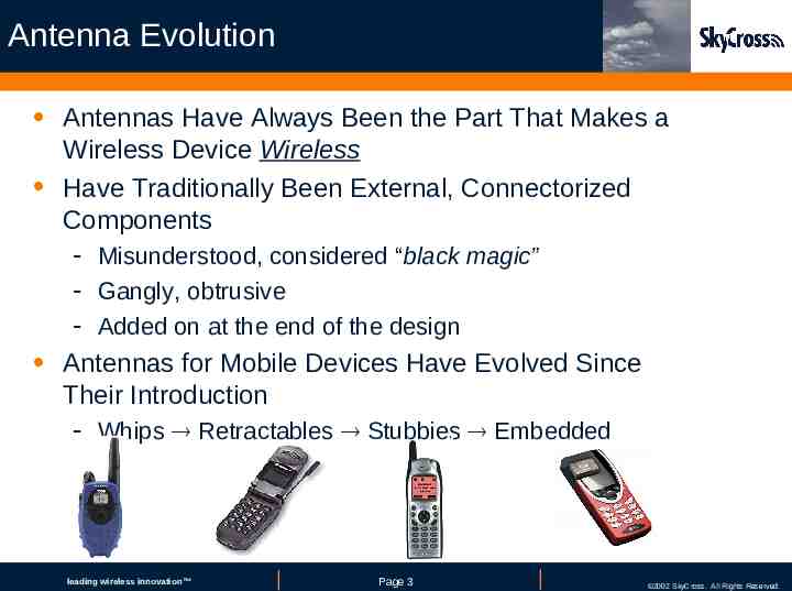
Antenna Evolution Antennas Have Always Been the Part That Makes a Wireless Device Wireless Have Traditionally Been External, Connectorized Components - Misunderstood, considered “black magic” - Gangly, obtrusive - Added on at the end of the design Antennas for Mobile Devices Have Evolved Since Their Introduction - Whips Retractables Stubbies Embedded leading leadingwireless wirelessinnovation innovation Page Page33 COMPANY 2002 CONFIDENTIAL SkyCross. All Rights Reserved.
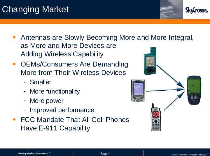
Changing Market Antennas are Slowly Becoming More and More Integral, as More and More Devices are Adding Wireless Capability OEMs/Consumers Are Demanding More from Their Wireless Devices - Smaller More functionality More power Improved performance FCC Mandate That All Cell Phones Have E-911 Capability leading leadingwireless wirelessinnovation innovation Page Page44 COMPANY 2002 CONFIDENTIAL SkyCross. All Rights Reserved.
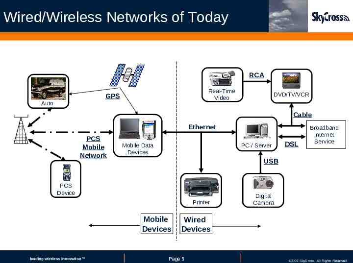
Wired/Wireless Networks of Today RCA Real-Time Video GPS Auto DVD/TV/VCR Cable Ethernet PCS Mobile Network Mobile Data Devices PC / Server USB PCS Device Printer Mobile Devices leading leadingwireless wirelessinnovation innovation DSL Broadband Internet Service Digital Camera Wired Devices Page Page55 COMPANY 2002 CONFIDENTIAL SkyCross. All Rights Reserved.
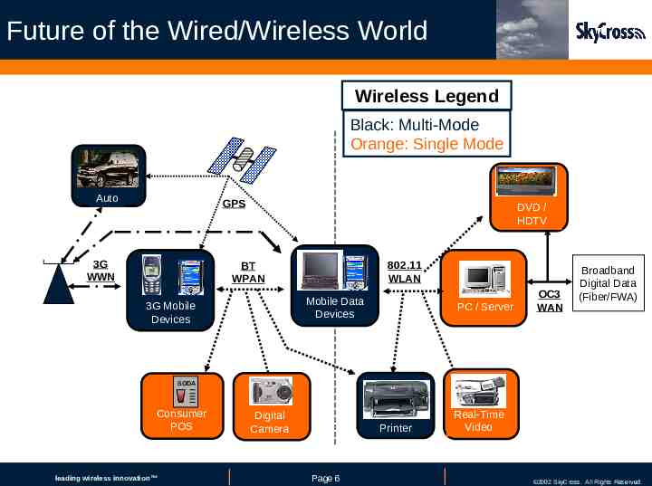
Future of the Wired/Wireless World Wireless Legend Black: Multi-Mode Orange: Single Mode Auto GPS 3G WWN DVD / HDTV 802.11 WLAN BT WPAN Mobile Data Devices 3G Mobile Devices PC / Server OC3 WAN Broadband Digital Data (Fiber/FWA) SODA Consumer POS leading leadingwireless wirelessinnovation innovation Digital Camera Printer Page Page66 Real-Time Video COMPANY 2002 CONFIDENTIAL SkyCross. All Rights Reserved.
Issues Facing Antenna Design Traditional Cost vs. Performance Tradeoffs Three Different Groups Have Three Different Sets of Priorities (OEMs Service Providers Consumers) Antenna Considerations (OEM Priority) 1) 2) 3) 4) Cost Size Performance Multiple operation modes leading leadingwireless wirelessinnovation innovation Page Page77 COMPANY 2002 CONFIDENTIAL SkyCross. All Rights Reserved.
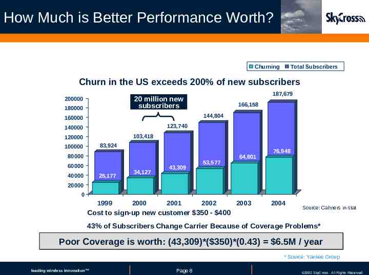
How Much is Better Performance Worth? Churning Total Subscribers Churn in the US exceeds 200% of new subscribers 187,679 20 million new subscribers 200000 180000 166,158 144,804 160000 123,740 140000 103,418 120000 83,924 100000 80000 60000 40000 25,177 34,127 43,309 53,577 64,801 76,948 20000 0 1999 2000 2001 2002 Cost to sign-up new customer 350 - 400 2003 2004 Source: Cahners in-stat 43% of Subscribers Change Carrier Because of Coverage Problems* Poor Coverage is worth: (43,309)*( 350)*(0.43) 6.5M / year * Source: Yankee Group leading leadingwireless wirelessinnovation innovation Page Page88 COMPANY 2002 CONFIDENTIAL SkyCross. All Rights Reserved.
1. Cost Antennas are Viewed as Components, with Traditional Price Points: - External whip/monopole assemblies: 1 - 2 - Internal/embedded antennas: 0.50 OEMs Very Reluctant to Consider Higher-priced Antennas for Existing Applications - Regardless of Performance Gains Alternative: Provide Multiple Functionality - Example: 3 antennas in 1 (Cell/PCS/ISM) - 3 for 1 multi-band antenna is better overall choice than 3 separate antennas for 1 each leading leadingwireless wirelessinnovation innovation Page Page99 COMPANY 2002 CONFIDENTIAL SkyCross. All Rights Reserved.
2. Reduced Size With the Evolution of Wireless Devices the Antenna has Been Forced to Reduce in Size Some Size Reduction Has Been Natural Result of Physics as Frequencies Increase - Example: commercial radio broadcast television analog cellular digital PCS wireless data But Further Reduction in Size Introduces New Complexities - Must continue to increase performance - But, must maintain a minimum certain size in order to meet bandwidth and energy requirements leading leadingwireless wirelessinnovation innovation Page Page10 10 COMPANY 2002 CONFIDENTIAL SkyCross. All Rights Reserved.
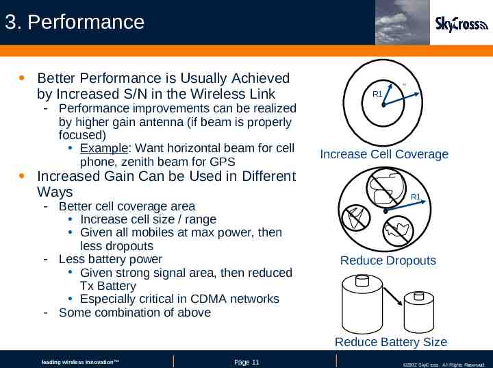
3. Performance Better Performance is Usually Achieved by Increased S/N in the Wireless Link - Performance improvements can be realized by higher gain antenna (if beam is properly focused) Example: Want horizontal beam for cell phone, zenith beam for GPS R2 R1 Increase Cell Coverage Increased Gain Can be Used in Different Ways - Better cell coverage area R1 Increase cell size / range Given all mobiles at max power, then less dropouts - Less battery power Given strong signal area, then reduced Tx Battery Especially critical in CDMA networks - Some combination of above Reduce Dropouts Reduce Battery Size leading leadingwireless wirelessinnovation innovation Page Page11 11 COMPANY 2002 CONFIDENTIAL SkyCross. All Rights Reserved.
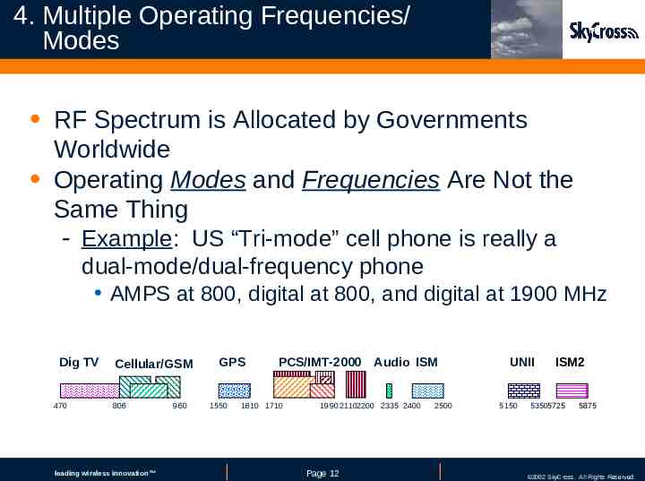
4. Multiple Operating Frequencies/ Modes RF Spectrum is Allocated by Governments Worldwide Operating Modes and Frequencies Are Not the Same Thing - Example: US “Tri-mode” cell phone is really a dual-mode/dual-frequency phone AMPS at 800, digital at 800, and digital at 1900 MHz Dig TV 470 Cellular/GSM 806 leading leadingwireless wirelessinnovation innovation 960 GPS 1550 PCS/IMT-2000 1610 1710 Audio ISM 1990 21102200 2335 2400 Page Page12 12 2500 UNII 5150 ISM2 53505725 5875 COMPANY 2002 CONFIDENTIAL SkyCross. All Rights Reserved.
Antenna Physics Antenna is Fundamentally a Transmission Line - Electrical energy is converted to Electromagnetic Radiation f c/ - as frequency goes up, wavelength gets shorter Loosely Speaking, Radiation Occurs Anywhere There is a Change in an Electric Current’s Velocity (Speed and/or Direction) - Consequently, antennas come in all forms of curved, bent and folded metal shapes designed to alter current velocity or density leading leadingwireless wirelessinnovation innovation Page Page13 13 COMPANY 2002 CONFIDENTIAL SkyCross. All Rights Reserved.
Antenna Performance Specifications Antenna is Traditionally Evaluated for Performance Under These Criteria A. B. C. D. E. Frequency Gain / directivity Return Loss / VSWR Bandwidth Impedance Today Additional Antenna Performance Parameters Must be Evaluated F. Efficiency G. Volumetric size leading leadingwireless wirelessinnovation innovation Page Page14 14 COMPANY 2002 CONFIDENTIAL SkyCross. All Rights Reserved.
A. Frequency of Operation Electromagnetic Spectrum Is Measured in Terms of Frequency Most Antennas Transceive Over a Narrow Frequency Range Which Is Usually 10% of the Center Frequency For Antennas, This Includes Both the Uplink and Downlink Frequencies (if duplex) - Example: (US PCS Tx and Rx) 1850 MHz to 1990 MHz leading leadingwireless wirelessinnovation innovation Page Page15 15 COMPANY 2002 CONFIDENTIAL SkyCross. All Rights Reserved.
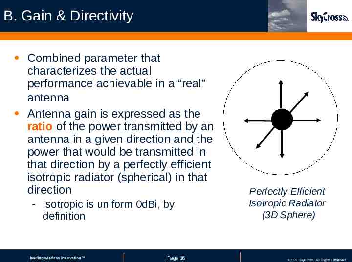
B. Gain & Directivity Combined parameter that characterizes the actual performance achievable in a “real” antenna Antenna gain is expressed as the ratio of the power transmitted by an antenna in a given direction and the power that would be transmitted in that direction by a perfectly efficient isotropic radiator (spherical) in that direction - Isotropic is uniform 0dBi, by definition leading leadingwireless wirelessinnovation innovation Page Page16 16 Perfectly Efficient Isotropic Radiator (3D Sphere) COMPANY 2002 CONFIDENTIAL SkyCross. All Rights Reserved.
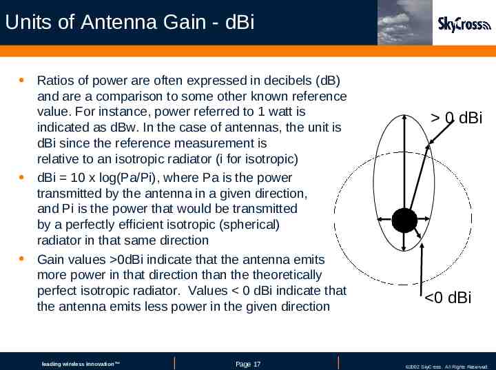
Units of Antenna Gain - dBi Ratios of power are often expressed in decibels (dB) and are a comparison to some other known reference value. For instance, power referred to 1 watt is indicated as dBw. In the case of antennas, the unit is dBi since the reference measurement is relative to an isotropic radiator (i for isotropic) dBi 10 x log(Pa/Pi), where Pa is the power transmitted by the antenna in a given direction, and Pi is the power that would be transmitted by a perfectly efficient isotropic (spherical) radiator in that same direction Gain values 0dBi indicate that the antenna emits more power in that direction than the theoretically perfect isotropic radiator. Values 0 dBi indicate that the antenna emits less power in the given direction leading leadingwireless wirelessinnovation innovation Page Page17 17 0 dBi 0 dBi COMPANY 2002 CONFIDENTIAL SkyCross. All Rights Reserved.
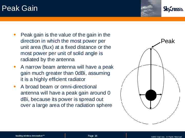
Peak Gain Peak gain is the value of the gain in the direction in which the most power per unit area (flux) at a fixed distance or the most power per unit of solid angle is radiated by the antenna A narrow beam antenna will have a peak gain much greater than 0dBi, assuming it is a highly efficient radiator A broad beam or omni-directional antenna will have a peak gain around 0 dBi, because its power is spread out over a large area of the radiation sphere leading leadingwireless wirelessinnovation innovation Page Page18 18 Peak COMPANY 2002 CONFIDENTIAL SkyCross. All Rights Reserved.
Average Gain As with peak gain, average gain for an antenna is also expressed in dBi, because it is referenced to a perfectly efficient isotropic radiator The highest possible average gain for an antenna is 0 dBi, because the total power emitted by an antenna can never be greater than the total power emitted by a perfectly efficient radiator. This assumes the averaging is done over the entire 4 steradian volume—the entire sphere Often average gain is expressed only over a portion of the sphere, such as a 2D planar cut in azimuth leading leadingwireless wirelessinnovation innovation Page Page19 19 COMPANY 2002 CONFIDENTIAL SkyCross. All Rights Reserved.
C. Return Loss / VSWR Difference between the power input to and the power reflected back from a discontinuity in a transmission circuit In a perfectly matched transmission system, there are no standing waves and the Voltage Standing Wave Ratio (a ratiometric measure of the crest to null of the voltage standing on the line) is 1:1 Antennas having VSWR less than 3:1 are acceptable for receive applications and low power transmission,with 2:1 being very good leading leadingwireless wirelessinnovation innovation Page Page20 20 COMPANY 2002 CONFIDENTIAL SkyCross. All Rights Reserved.
D. Bandwidth of Operation Amount of Spectrum Needed for a Particular Communications Channel or Group of Channels - Defined in units of frequency and is computed as the difference between an upper and lower band edge limit - Example: (PCS) 1990 – 1850 140 MHz BW 140 / 1920 (center) 7.3 % BW - Channel Bandwidth is usually much less than total allocated bandwidth Narrowband Antennas - Operate only on the band of frequencies for which the device was intended Broadband Antennas - Tend to perform less effectively than narrowband antennas but provide multiple frequency integration leading leadingwireless wirelessinnovation innovation Page Page21 21 COMPANY 2002 CONFIDENTIAL SkyCross. All Rights Reserved.
E. Input Impedance Antenna Input Impedance Is Traditionally Specified at 50 Ohms for Most Antenna Devices - Many not necessarily be optimal, but provides easy test / debug via standard coax test equipment - OEMs have begun to consider lower impedances, primarily driven to better match the output of the transmitting power amplifier (which is where most of the battery power is consumed) 75 Ohms Typical for Video Equipment leading leadingwireless wirelessinnovation innovation Page Page22 22 COMPANY 2002 CONFIDENTIAL SkyCross. All Rights Reserved.
F. Efficiency Direct Measure of How Well an Antenna Transforms Onboard Electrical Energy Into Transmitted Signal Energy - 100% efficient antenna would theoretically convert all input power into radiated power, with no loss to resistive or dielectric elements - Most all antennas in use exhibit at least 50% efficiency, with 70%-80% being very good designs leading leadingwireless wirelessinnovation innovation Page Page23 23 COMPANY 2002 CONFIDENTIAL SkyCross. All Rights Reserved.
G. Volumetric size Volumetric Size of the Best-designed Antenna Is Ultimately Limited by Theoretical Considerations That Depend on the Maximum Bandwidth Over Which the Antenna Must Operate - Some antennas exhibit a smaller occupied volume for a given degree of performance leading leadingwireless wirelessinnovation innovation Page Page24 24 COMPANY 2002 CONFIDENTIAL SkyCross. All Rights Reserved.
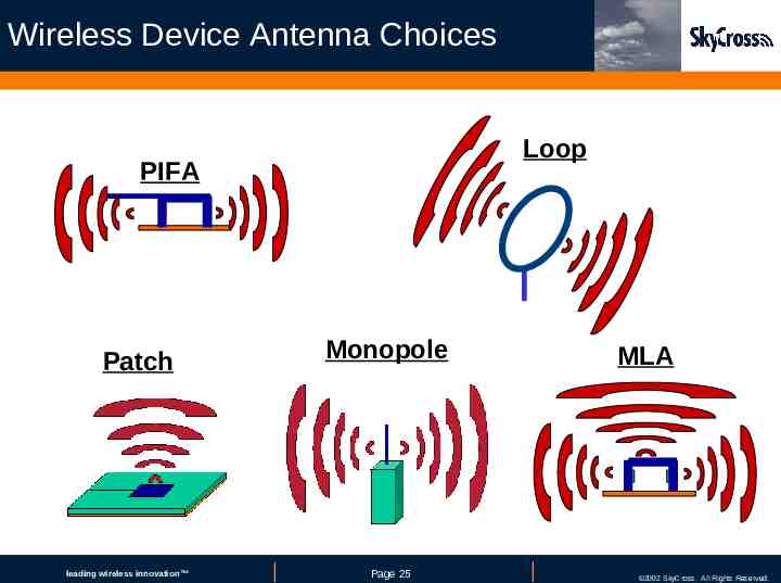
Wireless Device Antenna Choices Loop PIFA Patch leading leadingwireless wirelessinnovation innovation Monopole Page Page25 25 MLA COMPANY 2002 CONFIDENTIAL SkyCross. All Rights Reserved.
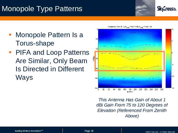
Monopole Type Patterns Monopole Pattern Is a Torus-shape PIFA and Loop Patterns Are Similar, Only Beam Is Directed in Different Ways This Antenna Has Gain of About 1 dBi Gain From 75 to 120 Degrees of Elevation (Referenced From Zenith Above) leading leadingwireless wirelessinnovation innovation Page Page26 26 COMPANY 2002 CONFIDENTIAL SkyCross. All Rights Reserved.
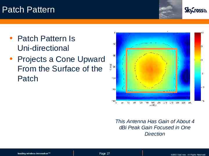
Patch Pattern Patch Pattern Is Uni-directional Projects a Cone Upward From the Surface of the Patch This Antenna Has Gain of About 4 dBi Peak Gain Focused in One Direction leading leadingwireless wirelessinnovation innovation Page Page27 27 COMPANY 2002 CONFIDENTIAL SkyCross. All Rights Reserved.
MLA and Other Patterns Meander Line Antenna (MLA) - Has both monopole and patch radiating modes, depending on operating frequency Monopole, Loop, PIFA and MLA May All Have Similar Beam Patterns - Depending on the size of the antenna relative to the wavelength of the signal, loop leading leadingwireless wirelessinnovation innovation Page Page28 28 COMPANY 2002 CONFIDENTIAL SkyCross. All Rights Reserved.
Embedded Antenna Considerations Include Antenna Designer as Part of the Design Team from Beginning Critical Considerations - Identify all frequency bands (GPS later ?) - Identify multiple-frequency RF front-end architecture Number of antenna feed points Diplexers, Tx/Rx paths, filtering needed - Identify orientation Desired beam pattern under consumer usage scenario Problem: PDA is used as both handheld and desktop - Plan and allocate for internal volume needed to achieve desired level of performance - Identify upfront the grounding scheme and adjacent metal surfaces leading leadingwireless wirelessinnovation innovation Page Page29 29 COMPANY 2002 CONFIDENTIAL SkyCross. All Rights Reserved.
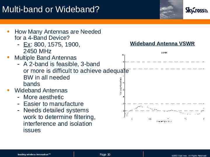
Multi-band or Wideband? How Many Antennas are Needed for a 4-Band Device? Wideband Antenna VSWR - Ex: 800, 1575, 1900, 2450 MHz Multiple Band Antennas - A 2-band is feasible, 3-band or more is difficult to achieve adequate BW in all needed bands Wideband Antennas - More aesthetic - Easier to manufacture - Needs detailed systems work to determine filtering, interference and isolation issues leading leadingwireless wirelessinnovation innovation Page Page30 30 COMPANY 2002 CONFIDENTIAL SkyCross. All Rights Reserved.
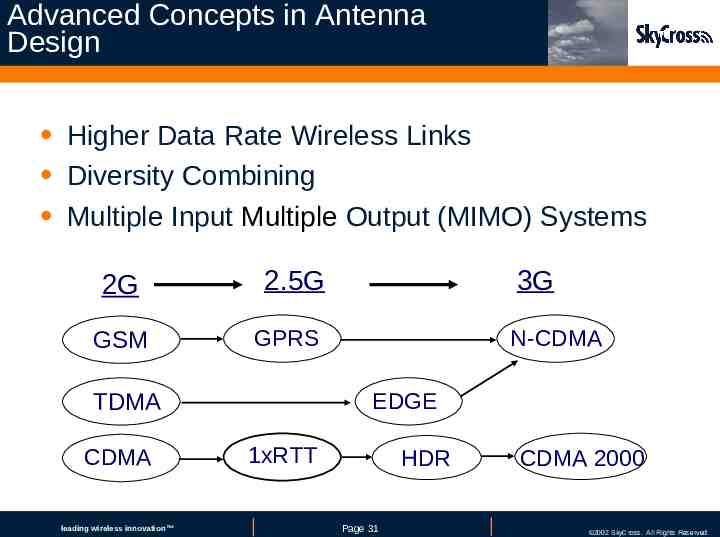
Advanced Concepts in Antenna Design Higher Data Rate Wireless Links Diversity Combining Multiple Input Multiple Output (MIMO) Systems 2G GSM 2.5G GPRS leading leadingwireless wirelessinnovation innovation N-CDMA EDGE TDMA CDMA 3G 1xRTT HDR Page Page31 31 CDMA 2000 COMPANY 2002 CONFIDENTIAL SkyCross. All Rights Reserved.
Higher and Higher Datarates The Convergence of Wireless Access and Broadband Internet Surfing Has Created a Demand for Low BER, High Datarate Wireless Systems Interference Dominates System Capacity Implying That Increasing Radiated Power at the Source Is Not the Solution The Electromagnetic Spectrum Is Limited and Efficient Usage Is Required From a Economic Perspective leading leadingwireless wirelessinnovation innovation Page Page32 32 COMPANY 2002 CONFIDENTIAL SkyCross. All Rights Reserved.
The Road Ahead Improved Spectral Efficiency Is Achievable in Environments of Interest for Commercial Wireless Services - Multipath characteristics of the channel determine the improvement in spectral efficiency - Published test results indicate that very small separation provides measurable improvements at mobile terminals As a Result, Multiple Antenna Diversity Is Being Introduced Into the Standards for Mobile 3G Systems (UMTS, EDGE) As Well As Indoor Systems (802.11 WLAN) leading leadingwireless wirelessinnovation innovation Page Page33 33 COMPANY 2002 CONFIDENTIAL SkyCross. All Rights Reserved.
Diversity Methods To Mitigate These Problems, Diversity Techniques are Being Developed - Spatial Diversity is a widespread technique based on the use of an - array of sufficiently spaced antennas at either transmitter or receiver Polarization Diversity takes advantage of existence of statistical independence of different polarization states as a wave is scattered in the environment Pattern Diversity uses the antenna itself to select angularly diverse components of the scattered wave to mitigate fading and increase SNR Temporal Diversity exploits the multidimensionality of the channel to improve SNR MIMO uses antenna arrays at both transmitter and receiver— multipath propagation can actually be exploited to establish multiple parallel channels leading leadingwireless wirelessinnovation innovation Page Page34 34 COMPANY 2002 CONFIDENTIAL SkyCross. All Rights Reserved.
Diversity Improvements There is Strong Evidence That One or More Forms of Diversity can Improve the Channel Performance of a Radio by Several dB - Cho, et al. 7 to 8 dB gain due to polarization A combination of height (spatial) and polarization diversity provide a robust scheme - Braun, et al. 9 dB with a two antenna configuration - Dietrich, Stutzman,et al. Also 5 to 7 dB - Many other references in Bibliography at GLOMO Project VPI leading leadingwireless wirelessinnovation innovation Page Page35 35 COMPANY 2002 CONFIDENTIAL SkyCross. All Rights Reserved.
Directional (Pattern) To Date, WLAN OEMs Have Not Exploited Directional - Traditional WLAN systems have relied on spatial only - Why not use 2 different WLAN antennas with higher peak gains focused in different directions? Example: 1 antenna omni-directional, 1 antenna patch diversity combines to better total hemi-spherical coverage “Smart Antennas” - Discriminate multi-path components - Process them separately Butler Matrix - If the signals from different directions can be processed separately, co-channel interference can be suppressed - Improve transmission quality and/or capacity - Can reduce delay spread leading leadingwireless wirelessinnovation innovation Page Page36 36 COMPANY 2002 CONFIDENTIAL SkyCross. All Rights Reserved.
Wireless Device Considerations for MIMO Multiple-Input, Multiple-Output (MIMO) Size Limited, Two Antennas Is About the Maximum Allowable in a Handheld Device Can Use Embedded Antenna as the Second One Can Exploit Polarization Diversity - Diversity Transmit and Diversity Receive - Second polarization for the whip antenna - Dual polarization antenna for the hidden antenna Treat Polarization Terms as Spatial Term Beam-formed Elements Again Treat Them as Spatial Terms and Process the Same Way leading leadingwireless wirelessinnovation innovation Page Page37 37 COMPANY 2002 CONFIDENTIAL SkyCross. All Rights Reserved.