A TURBINE AND turbine PUMP is a rotary engine that extracts

33 Slides1.15 MB
A TURBINE AND turbine PUMP is a rotary engine that extracts energy from a fluid flow and converts it into useful work Eg: steam turbine, gas turbine, hydraulic turbine Hydraulic Turbines transfer the kinetic energy and potential energy of water into a rotation . We can generate electricity by coupling to electric generator Pump is work consuming device and it is just opposite to turbine. Eg. Centrifugal pump
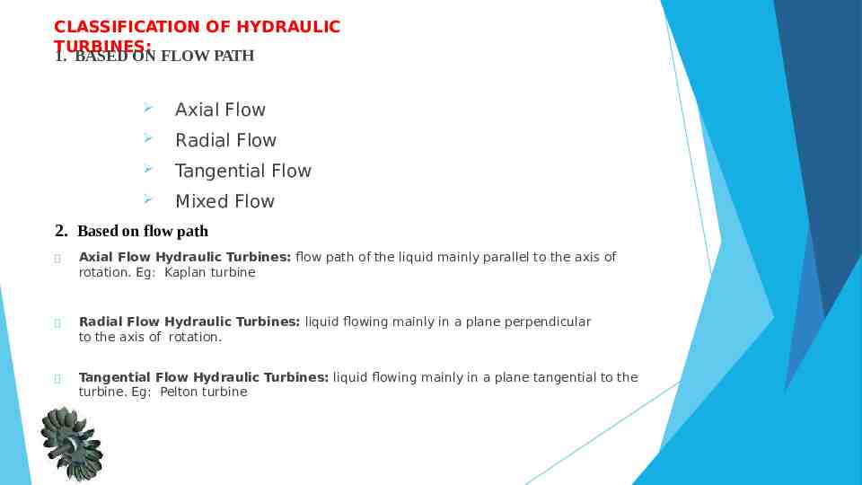
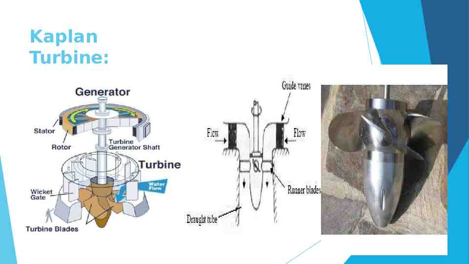
CLASSIFICATION OF HYDRAULIC TURBINES: 1. BASED ON FLOW PATH Axial Flow Radial Flow Tangential Flow Mixed Flow 2. Based on flow path Axial Flow Hydraulic Turbines: flow path of the liquid mainly parallel to the axis of rotation. Eg: Kaplan turbine Radial Flow Hydraulic Turbines: liquid flowing mainly in a plane perpendicular to the axis of rotation. Tangential Flow Hydraulic Turbines: liquid flowing mainly in a plane tangential to the turbine. Eg: Pelton turbine
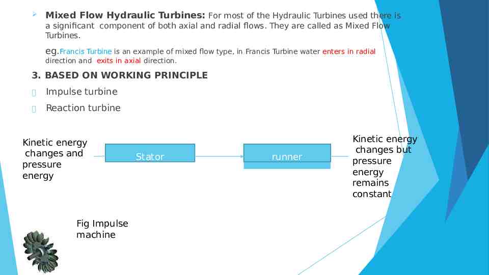
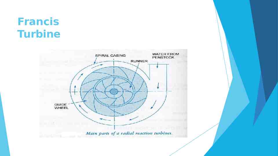
Mixed Flow Hydraulic Turbines: For most of the Hydraulic Turbines used there is a significant component of both axial and radial flows. They are called as Mixed Flow Turbines. eg.Francis Turbine is an example of mixed flow type, in Francis Turbine water enters in radial direction and exits in axial direction. 3. BASED ON WORKING PRINCIPLE Impulse turbine Reaction turbine Kinetic energy changes and pressure energy Fig Impulse machine Stator runner Kinetic energy changes but pressure energy remains constant
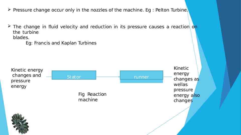
Pressure change occur only in the nozzles of the machine. Eg : Pelton Turbine. The change in fluid velocity and reduction in its pressure causes a reaction on the turbine blades. Eg: Francis and Kaplan Turbines Kinetic energy changes and pressure energy Stator Fig Reaction machine runner Kinetic energy changes as wellas pressure energy also changes
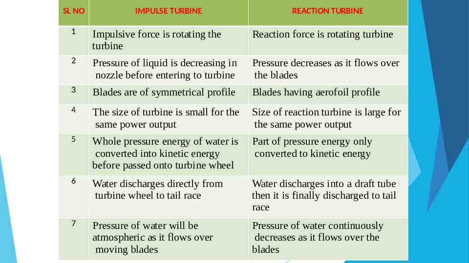
SL NO IMPULSE TURBINE REACTION TURBINE 1 Impulsive force is rotating the turbine Reaction force is rotating turbine 2 Pressure of liquid is decreasing in nozzle before entering to turbine Pressure decreases as it flows over the blades 3 Blades are of symmetrical profile Blades having aerofoil profile 4 The size of turbine is small for the same power output Size of reaction turbine is large for the same power output 5 Whole pressure energy of water is converted into kinetic energy before passed onto turbine wheel Part of pressure energy only converted to kinetic energy 6 Water discharges directly from turbine wheel to tail race Water discharges into a draft tube then it is finally discharged to tail race 7 Pressure of water will be atmospheric as it flows over moving blades Pressure of water continuously decreases as it flows over the blades
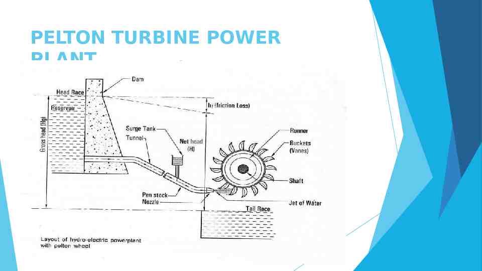
PELTON TURBINE POWER PLANT
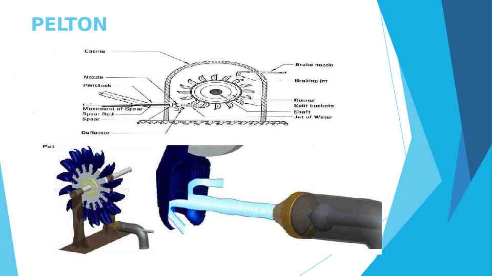
PELTON TURBINE
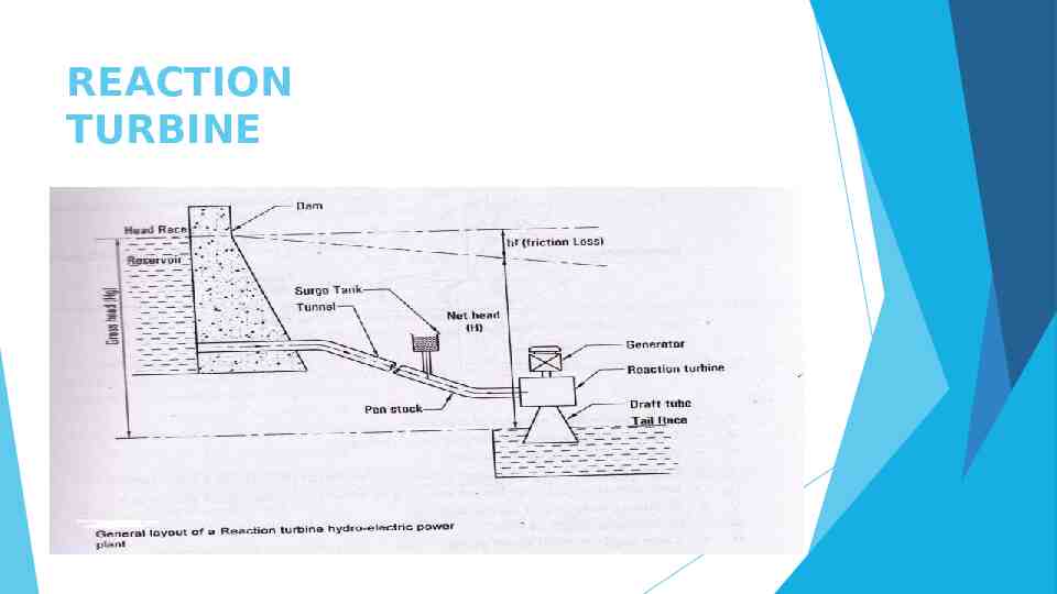
REACTION TURBINE
Francis Turbine
Kaplan Turbine:
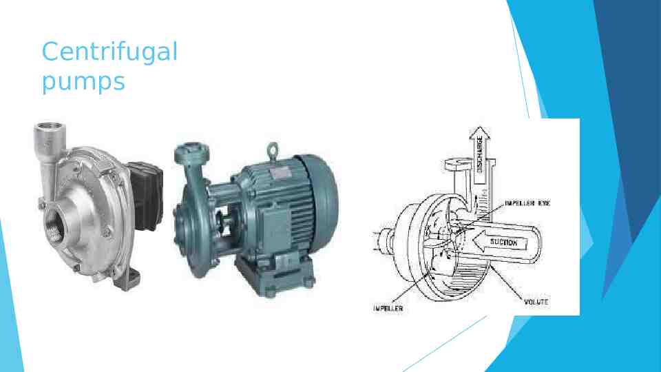
CLASSIFICATION OF PUMPS Pumps are broadly classified into 1. Positive- displacement pumps 2. Rotodynamic pumps Positive- displacement pumps: They make a fluid move by trapping a fixed amount and displacing the trapped volume into the discharge pipe. Discharge is directly proportional to speed. Eg : Reciprocating pump, Vane pump, Gear pump Rotodynamic pumps: It is a machine in which energy is continuously imparted to the pumped fluid by means of a rotor and thus fluid is raised to higher elevation. Eg: Centrifugal pump
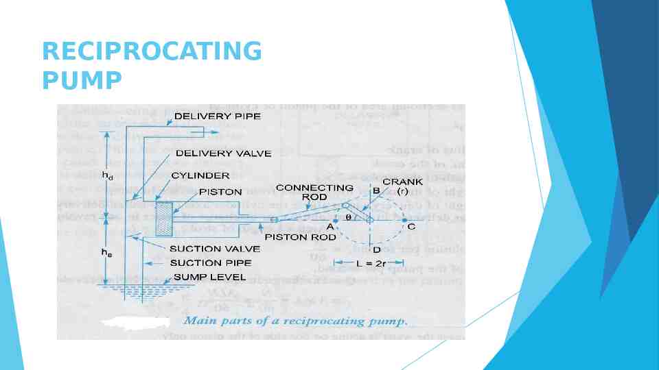
RECIPROCATING PUMP
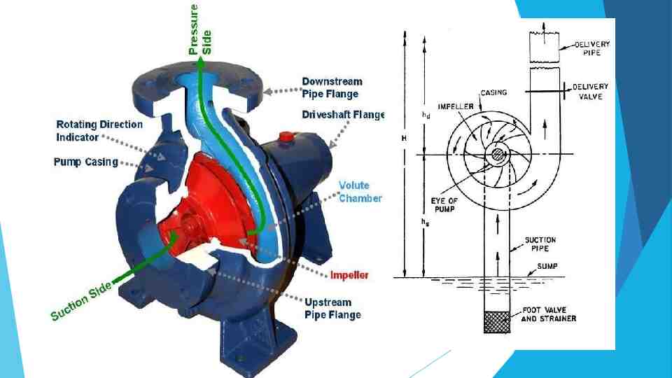
Centrifugal pumps
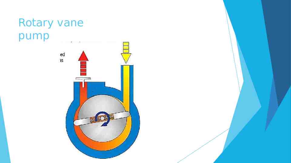
Rotary vane pump
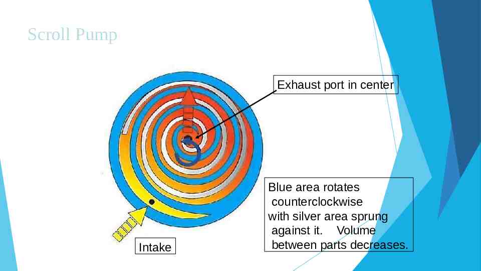
Scroll Pump Exhaust port in center Intake Blue area rotates counterclockwise with silver area sprung against it. Volume between parts decreases.
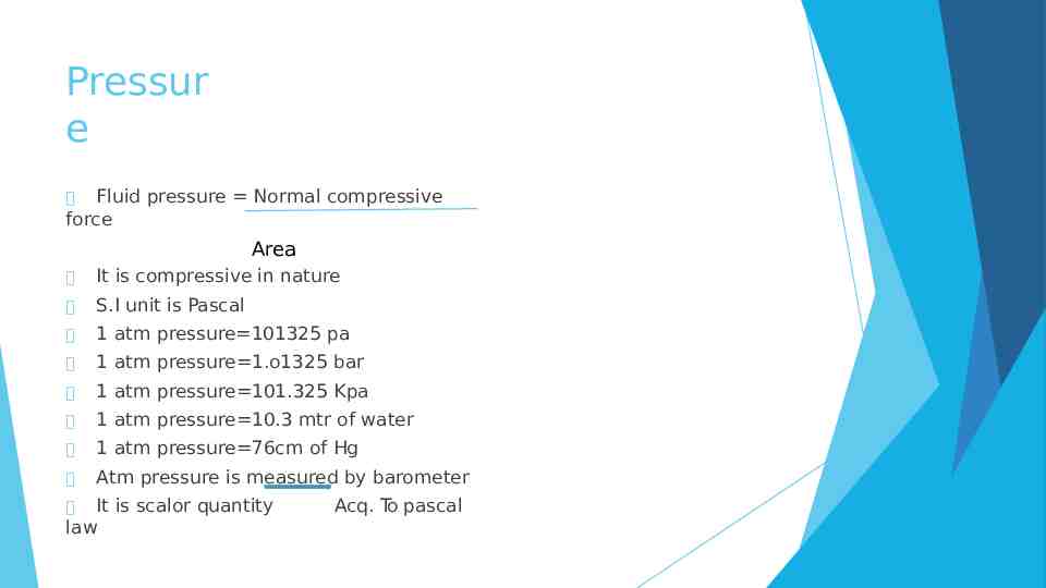
Pressur e Fluid pressure Normal compressive force Area It is compressive in nature S.I unit is Pascal 1 atm pressure 101325 pa 1 atm pressure 1.o1325 bar 1 atm pressure 101.325 Kpa 1 atm pressure 10.3 mtr of water 1 atm pressure 76cm of Hg Atm pressure is measured by barometer It is scalor quantity law Acq. To pascal
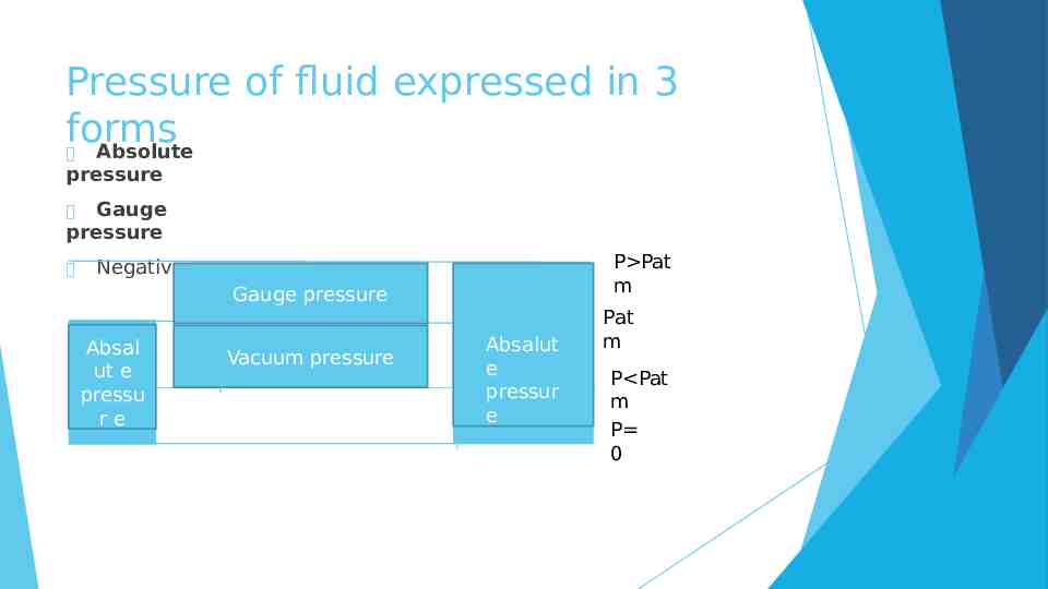
Pressure of fluid expressed in 3 forms Absolute pressure Gauge pressure P Pat m Negative gauge Gauge pressure Absal ut e pressu re Vacuum pressure Absalut e pressur e Pat m P Pat m P 0
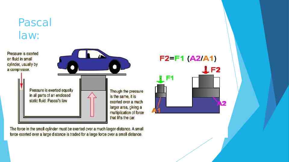
Pascal law:
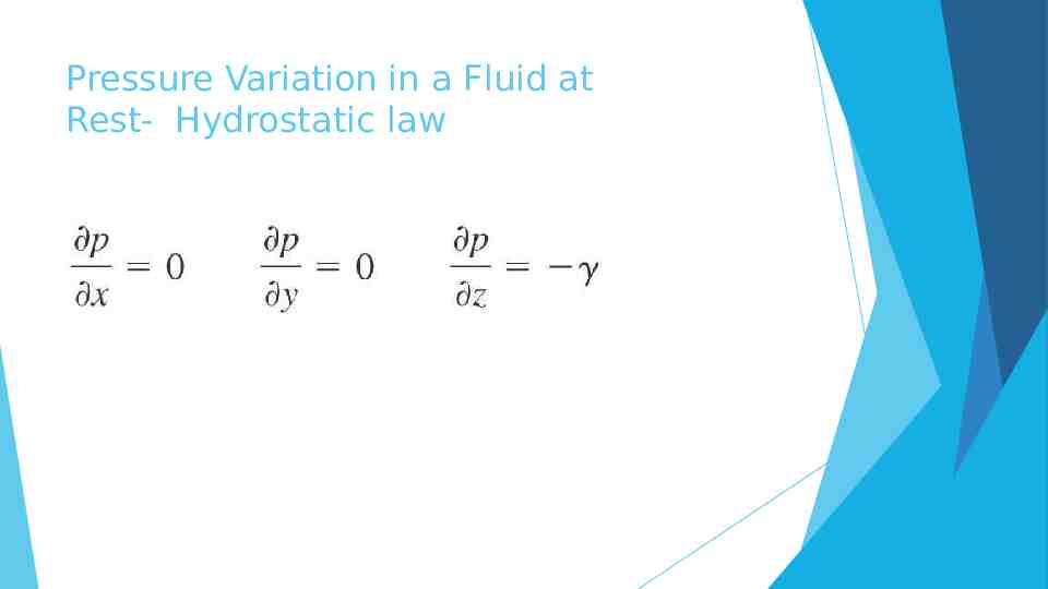
Pressure Variation in a Fluid at Rest- Hydrostatic law
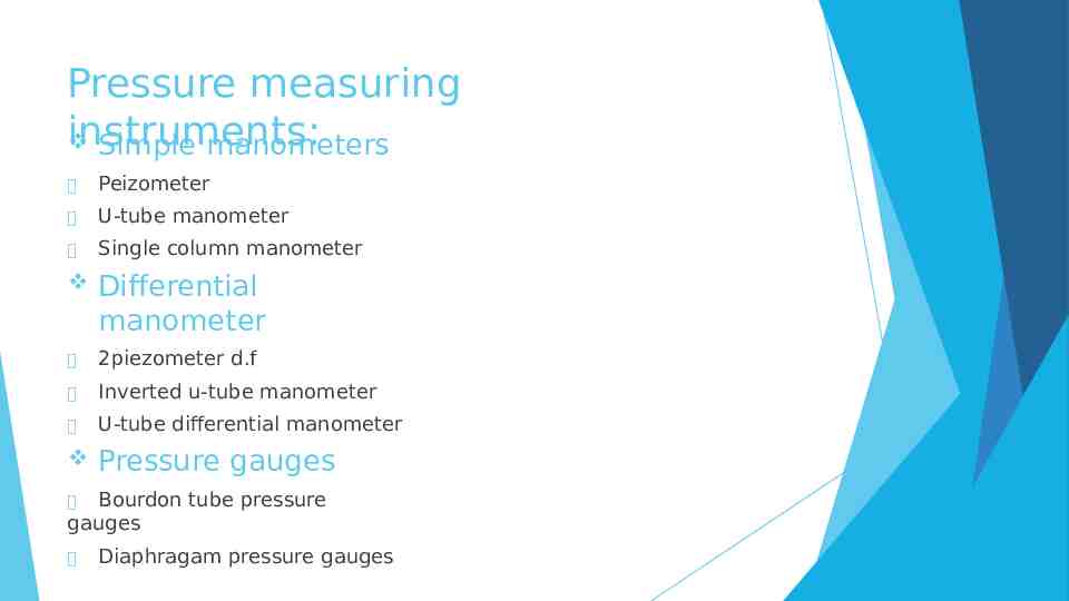
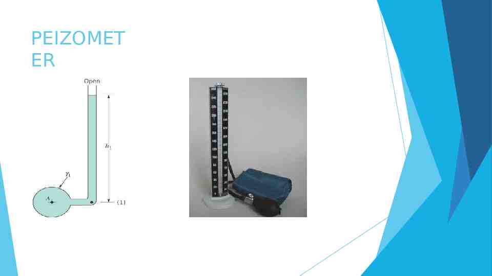
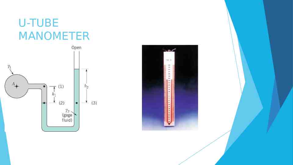
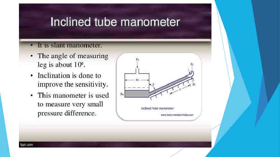
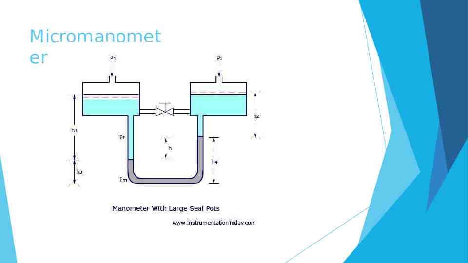
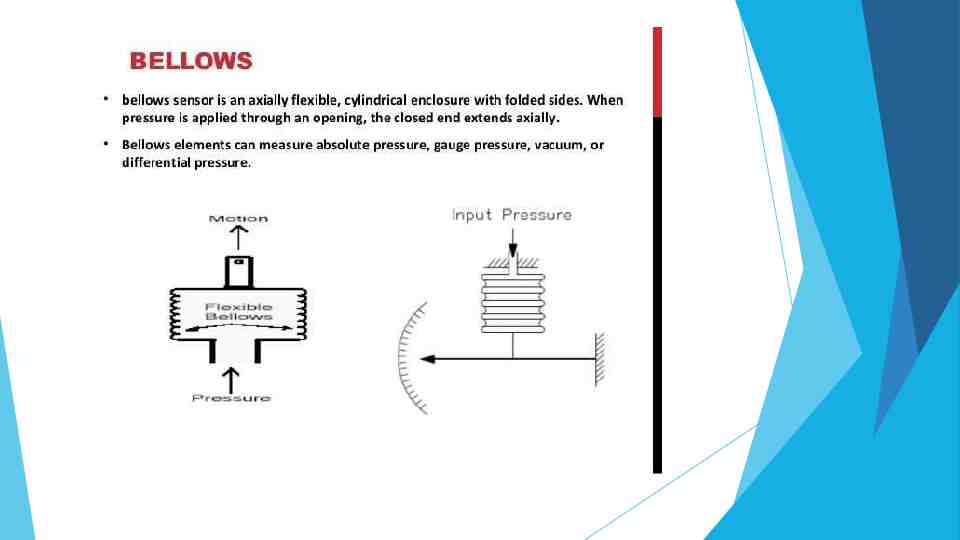
Pressure measuring instruments: Simple manometers Peizometer U-tube manometer Single column manometer Differential manometer 2piezometer d.f Inverted u-tube manometer U-tube differential manometer Pressure gauges Bourdon tube pressure gauges Diaphragam pressure gauges
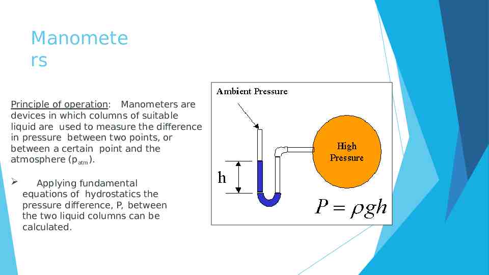
Manomete rs Principle of operation: Manometers are devices in which columns of suitable liquid are used to measure the difference in pressure between two points, or between a certain point and the atmosphere (patm). Applying fundamental equations of hydrostatics the pressure difference, P, between the two liquid columns can be calculated.
PEIZOMET ER
U-TUBE MANOMETER
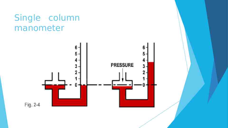
Single column manometer
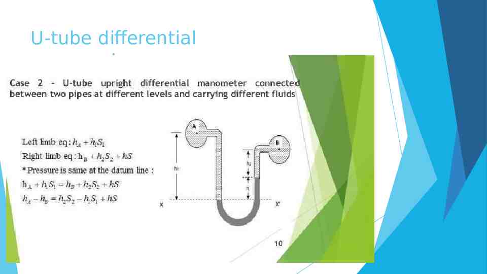
U-tube differential manometer
Micromanomet er
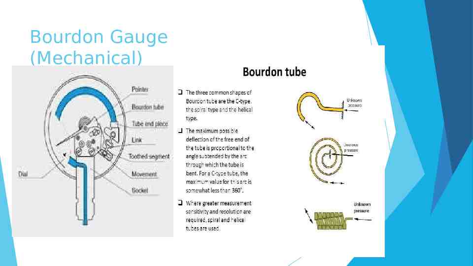
Bourdon Gauge (Mechanical)
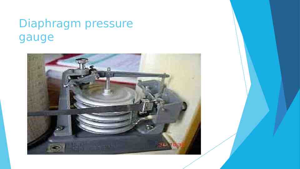
Diaphragm pressure gauge
Thank You