TIG Welding Introduction

36 Slides1.61 MB
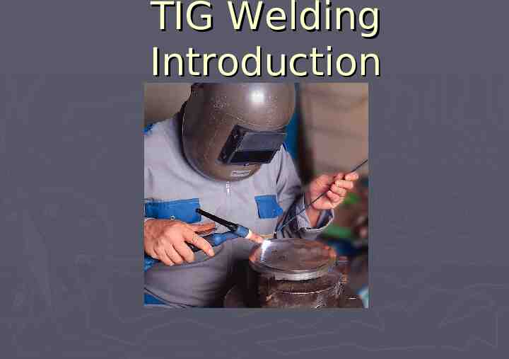
TIG Welding Introduction
Outline Background Advantages and Disadvantages Safety Preparation for TIG Welding Techniques for Basic Weld Joints TIG Shielding Gases Welding Parameters Tungsten Electrode Selection Conclusion 2
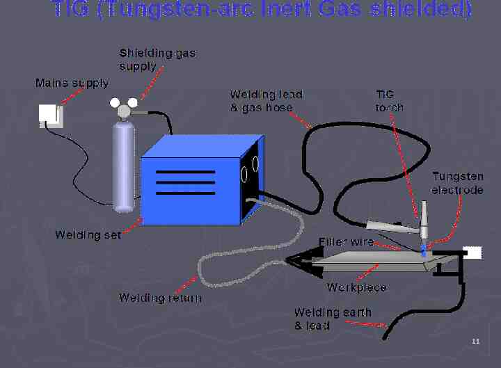
Background What is TIG? Tungsten Inert Gas Also referred to as GTAW Gas Shielded Tungsten Arc Welding In TIG welding, a tungsten electrode heats the metal and sheilding gas (most typically Argon) protects the weld from airborne contaminants 3
Background TIG welding uses a non-consumable tungsten Filler metal, when required, is added by hand Shielding gas protects the weld and tungsten 4
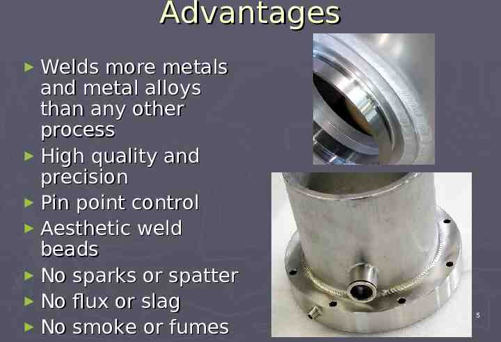
Advantages Welds more metals and metal alloys than any other process High quality and precision Pin point control Aesthetic weld beads No sparks or spatter No flux or slag No smoke or fumes 5
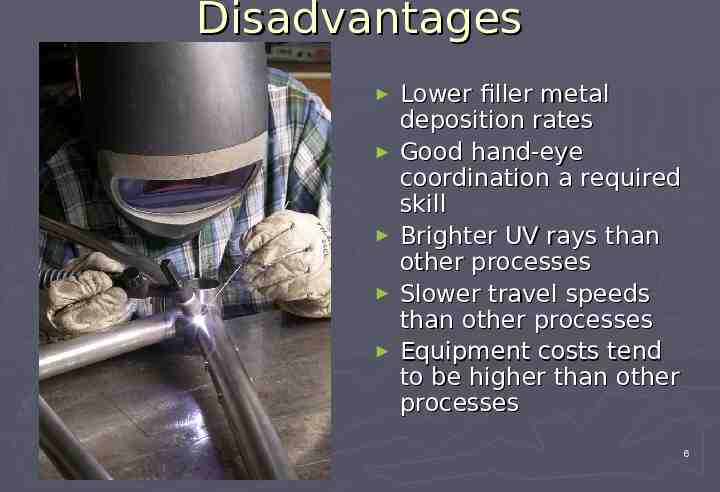
Disadvantages Lower filler metal deposition rates Good hand-eye coordination a required skill Brighter UV rays than other processes Slower travel speeds than other processes Equipment costs tend to be higher than other processes 6
Safety Electric shock can kill. Always wear dry insulating gloves Insulate yourself from work and ground Do not touch live electrical parts Keep all panels and covers securely in place Fumes health. and gases can be hazardous to your Keep your head out of the fumes Ventilate area, or use breathing device 7
Safety Welding can cause fire or explosion. Do not weld near flammable material Watch for fire; keep extinguisher nearby Do not locate unit over combustible surfaces Do not weld on closed containers Arc rays can burn eyes and skin; Noise can damage hearing. Wear welding helmet with correct shade of filter Wear correct eye, ear, and body protection 8
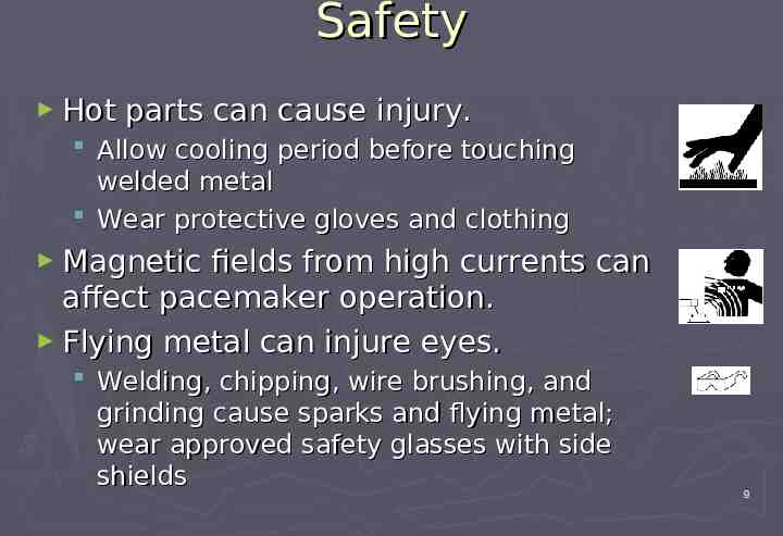
Safety Hot parts can cause injury. Allow cooling period before touching welded metal Wear protective gloves and clothing Magnetic fields from high currents can affect pacemaker operation. Flying metal can injure eyes. Welding, chipping, wire brushing, and grinding cause sparks and flying metal; wear approved safety glasses with side shields 9
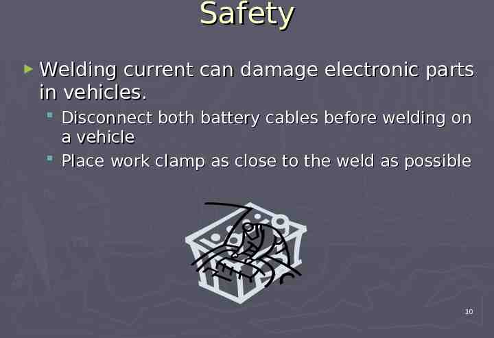
Safety Welding current can damage electronic parts in vehicles. Disconnect both battery cables before welding on a vehicle Place work clamp as close to the weld as possible 10
11
Preparation for TIG Welding Preparing the Weld Joint Many problems are a direct result of using improper methods to prepare the weld joint One of the most common is the improper use of grinding wheels Soft materials like aluminum may get embedded with abrasive particles resulting in excessive porosity Grinding wheels should be cleaned and dedicated only to the material being welded 12
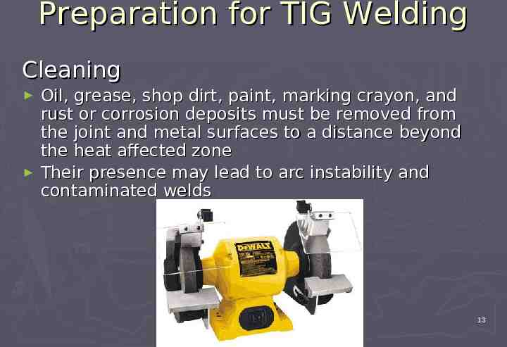
Preparation for TIG Welding Cleaning Oil, grease, shop dirt, paint, marking crayon, and rust or corrosion deposits must be removed from the joint and metal surfaces to a distance beyond the heat affected zone Their presence may lead to arc instability and contaminated welds ENBE 499 13
Preparation for TIG Welding Preparing Aluminum for Welding Very susceptible to contaminants Surface oxide must be removed Special abrasive wheels are available for aluminum Stainless steel wire brushes recommended Both sides of the joint should be cleaned if it contains foreign material 14
Preparation for TIG Welding Preparing Stainless Steel for Welding Should be thoroughly cleaned Foreign material may cause porosity in welds and carburetion of the surface which decreases the corrosion resistance Stainless steel wire brushes recommended 15
Preparation for TIG Welding Preparing Mild Steel for Welding Should be mechanically cleaned Scale, rust, paint, oil, grease, or any surface contaminants should be removed 16
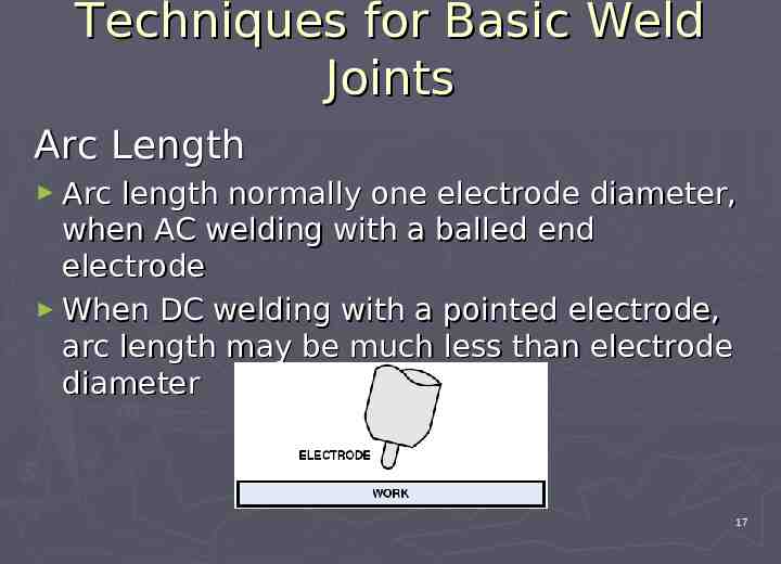
Techniques for Basic Weld Joints Arc Length Arc length normally one electrode diameter, when AC welding with a balled end electrode When DC welding with a pointed electrode, arc length may be much less than electrode diameter 17
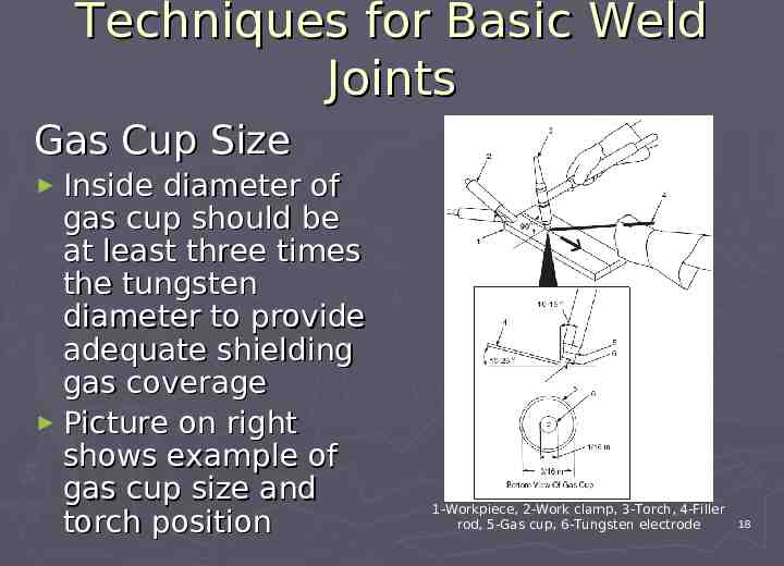
Techniques for Basic Weld Joints Gas Cup Size Inside diameter of gas cup should be at least three times the tungsten diameter to provide adequate shielding gas coverage Picture on right shows example of gas cup size and torch position 1-Workpiece, 2-Work clamp, 3-Torch, 4-Filler rod, 5-Gas cup, 6-Tungsten electrode 18
Techniques for Basic Weld Joints Electrode Extension Refers to distance the tungsten extends out beyond the gas cup May vary from flush with the gas cup to no more than the inside diameter of the gas cup Longer the extension, the more likely it may contact something by accident General rule would be to start with an extension of one electrode diameter 19
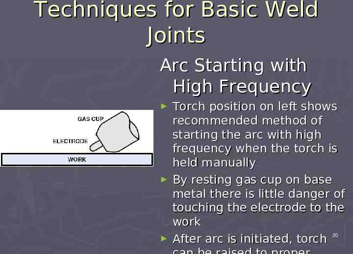
Techniques for Basic Weld Joints Arc Starting with High Frequency Torch position on left shows recommended method of starting the arc with high frequency when the torch is held manually By resting gas cup on base metal there is little danger of touching the electrode to the work After arc is initiated, torch 20
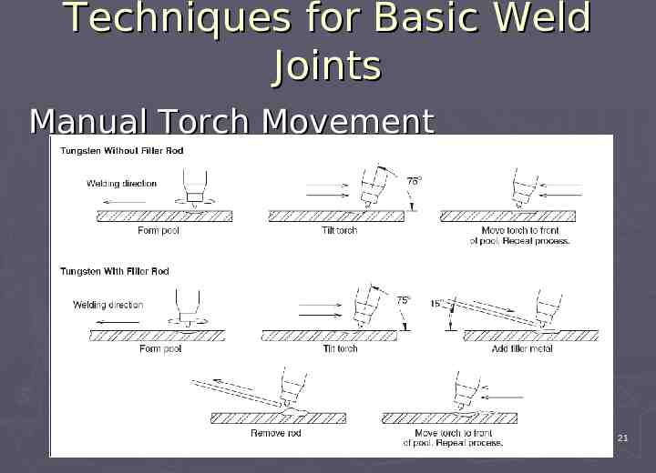
Techniques for Basic Weld Joints Manual Torch Movement ENBE 499 21
Techniques for Basic Weld Joints Manual Torch Movement Torch and filler rod must be moved progressively and smoothly so the weld pool, the hot filler rod end, and the solidifying weld are not exposed to air that will contaminate the weld metal area or heat affected zone When arc is turned off, postflow of shielding gas should shield the weld pool, electrode, and hot end of the filler rod 22
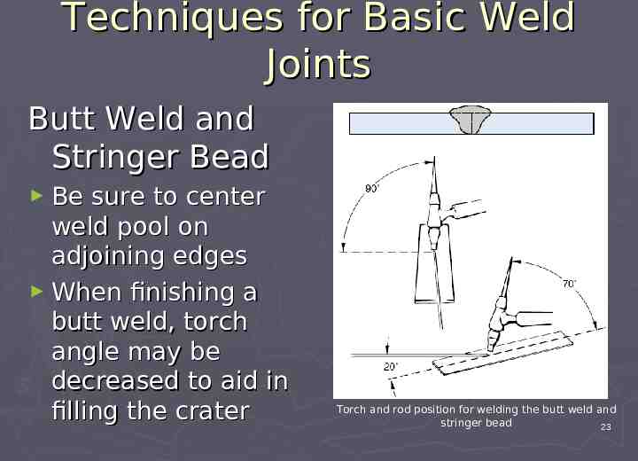
Techniques for Basic Weld Joints Butt Weld and Stringer Bead Be sure to center weld pool on adjoining edges When finishing a butt weld, torch angle may be decreased to aid in filling the crater Torch and rod position for welding the butt weld and stringer bead 23
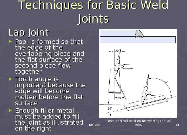
Techniques for Basic Weld Joints Lap Joint Pool is formed so that the edge of the overlapping piece and the flat surface of the second piece flow together Torch angle is important because the edge will become molten before the flat surface Enough filler metal must be added to fill the joint as illustrated ENBE 499 on the right Torch and rod position for welding the lap joint 24
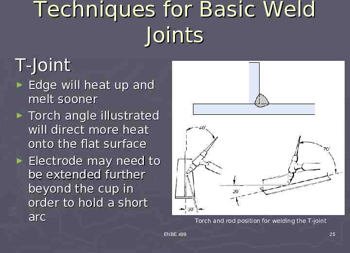
Techniques for Basic Weld Joints T-Joint Edge will heat up and melt sooner Torch angle illustrated will direct more heat onto the flat surface Electrode may need to be extended further beyond the cup in order to hold a short arc Torch and rod position for welding the T-joint ENBE 499 25
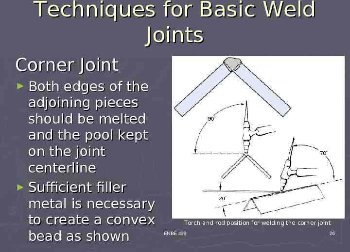
Techniques for Basic Weld Joints Corner Joint Both edges of the adjoining pieces should be melted and the pool kept on the joint centerline Sufficient filler metal is necessary to create a convex bead as shown Torch and rod position for welding the corner joint ENBE 499 26
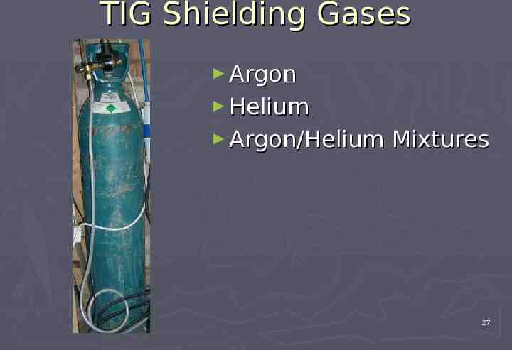
TIG Shielding Gases Argon Helium Argon/Helium Mixtures 27
TIG Shielding Gases Helium Argon Good arc starting Good cleaning action Good arc stability Focused arc cone Lower arc voltages 10-30 CFH flow rates Faster travel speeds Increased penetration Difficult arc starting Less cleaning action Less low amp stability Flared arc cone Higher arc voltages Higher flow rates (2x) Higher cost than argon 28
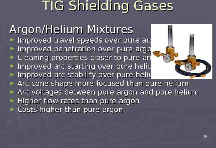
TIG Shielding Gases Argon/Helium Mixtures Improved travel speeds over pure argon Improved penetration over pure argon Cleaning properties closer to pure argon Improved arc starting over pure helium Improved arc stability over pure helium Arc cone shape more focused than pure helium Arc voltages between pure argon and pure helium Higher flow rates than pure argon Costs higher than pure argon 29
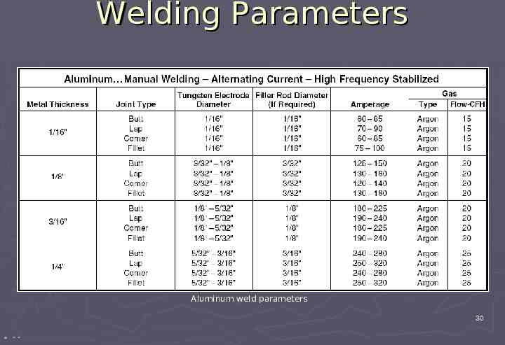
Welding Parameters Aluminum weld parameters 30 * “”
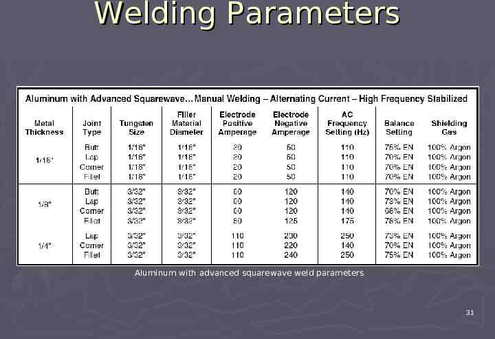
Welding Parameters Aluminum with advanced squarewave weld parameters 31
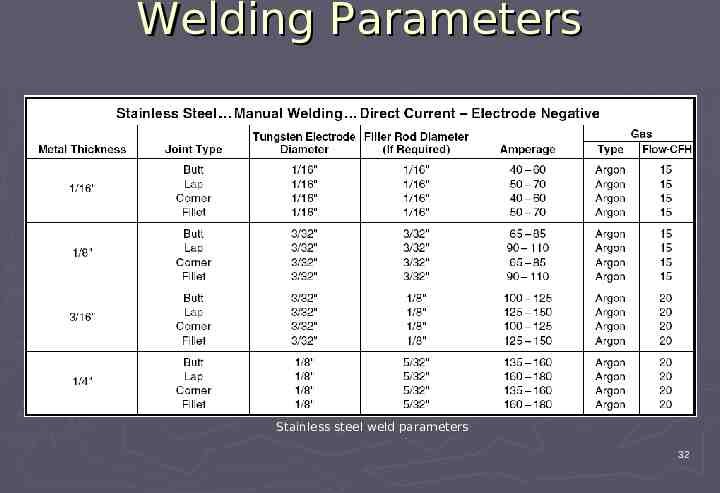
Welding Parameters Stainless steel weld parameters 32
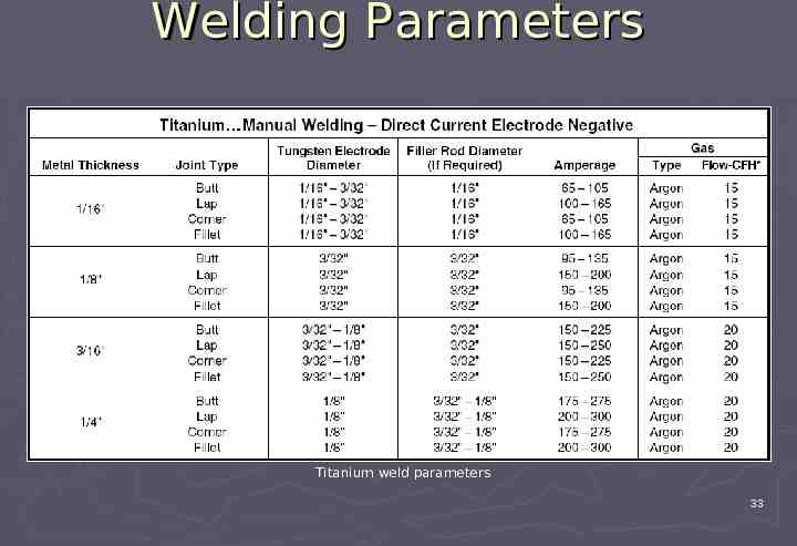
Welding Parameters Titanium weld parameters 33
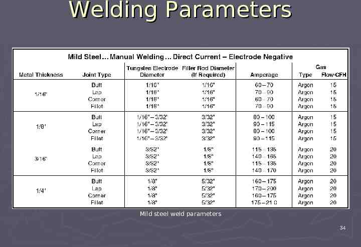
Welding Parameters Mild steel weld parameters 34
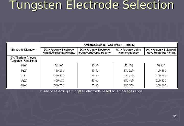
Tungsten Electrode Selection Guide to selecting a tungsten electrode based on amperage range 35
Conclusion TIG welding is an exciting skill that proves itself useful in countless applications Because it welds more metal and metal alloys than any other process, TIG welding should be regarded as an important tool where experience is the teacher Welding parameters and tungsten electrode selection tables are recommended values and should be used as a guideline 36