Stycast Insertion Part 3 and preliminary glue picture on


22 Slides2.79 MB
Stycast Insertion Part 3 and preliminary glue picture on samples 10-10-06
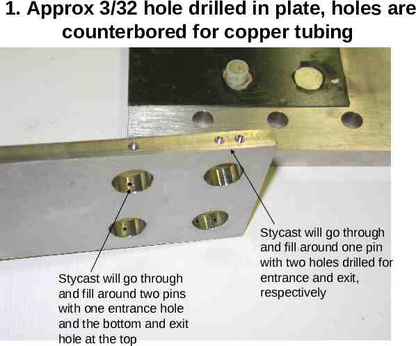
1. Approx 3/32 hole drilled in plate, holes are counterbored for copper tubing Stycast will go through and fill around two pins with one entrance hole and the bottom and exit hole at the top Stycast will go through and fill around one pin with two holes drilled for entrance and exit, respectively
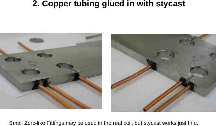
2. Copper tubing glued in with stycast Small Zerc-like Fittings may be used in the real coil, but stycast works just fine.
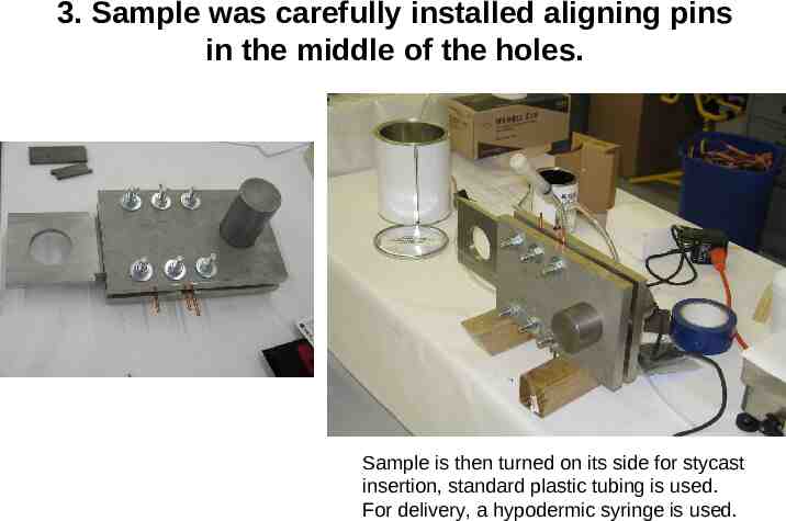
3. Sample was carefully installed aligning pins in the middle of the holes. Sample is then turned on its side for stycast insertion, standard plastic tubing is used. For delivery, a hypodermic syringe is used.
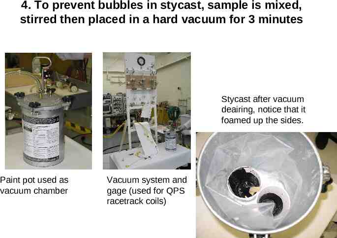
4. To prevent bubbles in stycast, sample is mixed, stirred then placed in a hard vacuum for 3 minutes Stycast after vacuum deairing, notice that it foamed up the sides. Paint pot used as vacuum chamber Vacuum system and gage (used for QPS racetrack coils)
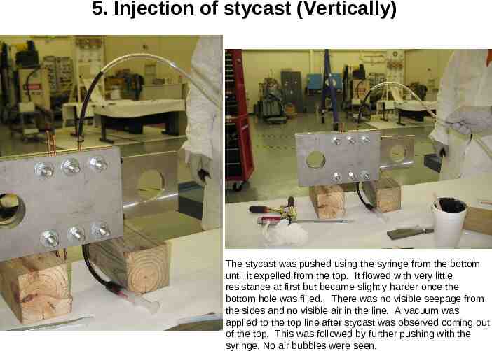
5. Injection of stycast (Vertically) The stycast was pushed using the syringe from the bottom until it expelled from the top. It flowed with very little resistance at first but became slightly harder once the bottom hole was filled. There was no visible seepage from the sides and no visible air in the line. A vacuum was applied to the top line after stycast was observed coming out of the top. This was followed by further pushing with the syringe. No air bubbles were seen.
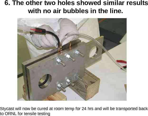
6. The other two holes showed similar results with no air bubbles in the line. Stycast will now be cured at room temp for 24 hrs and will be transported back to ORNL for tensile testing
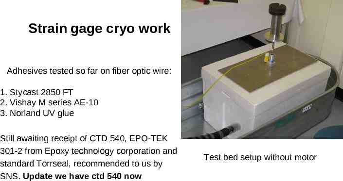
Strain gage cryo work Adhesives tested so far on fiber optic wire: 1. Stycast 2850 FT 2. Vishay M series AE-10 3. Norland UV glue Still awaiting receipt of CTD 540, EPO-TEK 301-2 from Epoxy technology corporation and standard Torrseal, recommended to us by SNS. Update we have ctd 540 now Test bed setup without motor
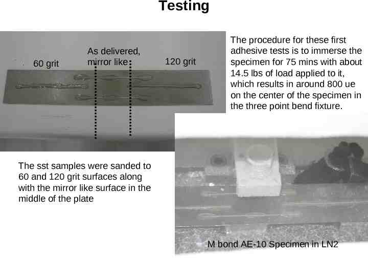
Testing 60 grit As delivered, mirror like 120 grit The procedure for these first adhesive tests is to immerse the specimen for 75 mins with about 14.5 lbs of load applied to it, which results in around 800 ue on the center of the specimen in the three point bend fixture. The sst samples were sanded to 60 and 120 grit surfaces along with the mirror like surface in the middle of the plate M bond AE-10 Specimen in LN2
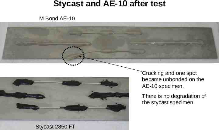
Stycast and AE-10 after test M Bond AE-10 Cracking and one spot became unbonded on the AE-10 specimen. There is no degradation of the stycast specimen Stycast 2850 FT
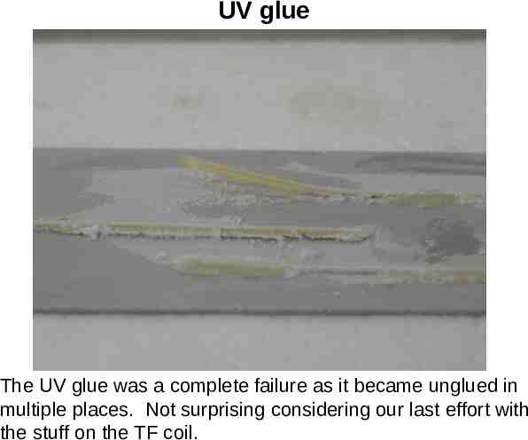
UV glue The UV glue was a complete failure as it became unglued in multiple places. Not surprising considering our last effort with the stuff on the TF coil.
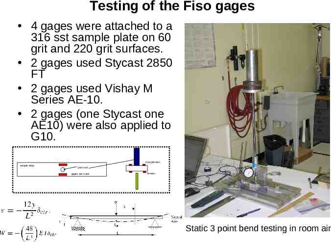
Testing of the Fiso gages 4 gages were attached to a 316 sst sample plate on 60 grit and 220 grit surfaces. 2 gages used Stycast 2850 FT 2 gages used Vishay M Series AE-10. 2 gages (one Stycast one AE10) were also applied to G10. SST (50 grit paper) SST (as received, mirror like) g-10 strips QPS beam SST, (200 grit, [if needed]) 1 1 1 1 1 total 4 4 4 4 4 STY,UV,AE,CTD STY,UV,AE,CTD STY,UV,AE,CTD STY,UV,AE,CTD STY,UV,AE,CTD 4 4 4 4 4 20 Note: as methods are discounted, more gages will be available Compression sample strips push rod gages are in red Tension Static 3 point bend testing in room air
Notes Fiber optic gages have been attached to both stainless steel and g-10 using stycast and AE10. The AE-10 Gages can be recovered by using a stripping agent if they fail and come off. Data Acquisition software is installed for the UMI and FTI-10. Room temperature testing (steady state) of the gages and data acquisition system shall commence tomorrow.
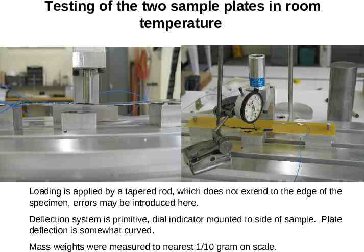
Testing of the two sample plates in room temperature Loading is applied by a tapered rod, which does not extend to the edge of the specimen, errors may be introduced here. Deflection system is primitive, dial indicator mounted to side of sample. Plate deflection is somewhat curved. Mass weights were measured to nearest 1/10 gram on scale.
Stainless Steel Specimens at room temperature TEST AVERAGES (1-4) MEASURED MEASURED PREDICTED DEFLECTION % error (load) LOAD (lbs) STRAIN (IN) 0.022 2.06 5.25 117.56 0.04525 4 0.64 241.80 0.06925 6 2.61 370.05 0.1695 14.65 2.85 905.77 return strain GAGE 1 GAGE 2 GAGE 3 GAGE 4 80.25 161.50 241.75 587.00 -3.67 -96.00 -194.25 -271.75 -663.50 -2.33 111.75 224.75 344.00 843.50 9.67 -102.00 -198.25 -298.25 -723.25 -3.67 TEST AVERAGES (5-8) Plate Flipped MEASURED MEASURED PREDICTED DEFLECTION % error (load) LOAD (lbs) STRAIN (IN) 0.022 2.06 5.25 118 0.045 4 0.09 240 0.06875 6 1.90 367 0.169 14.65 2.56 903 return strain % error Strain (ue) GAGE 1 GAGE 2 GAGE 3 GAGE 4 31.74 33.21 34.67 35.19 18.34 19.67 26.56 26.75 4.94 7.05 7.04 6.87 % error Strain (ue) GAGE 1 GAGE 2 GAGE 3 GAGE 4 -108.00 -189.67 -269.33 -699.33 -538.25 98.5 205.75 309 793.5 8.75 -118.25 -234.75 -356.25 -864.25 -10.25 103.25 205.5 306.25 758 12.5 GAGE 1 GAGE 2 GAGE 3 GAGE 4 8.13 21.13 26.69 22.56 16.21 14.44 15.89 12.14 -0.58 2.38 3.03 4.30 AE10 Specimen #1 had problems GAGE 1 GAGE 2 GAGE 3 GAGE 4 adhesive AE10 AE11 STY STY gage number 6442 6443 6444 6445 Location Bottom Top Bottom Top grit 60 GRIT 220 GRIT 60 GRIT 220 GRIT 13.24 18.01 19.40 20.15 Errors on Stycast 20% Return strains were a few micro-strain typically Gage readings are very repeatable 12.17 14.54 16.64 16.07
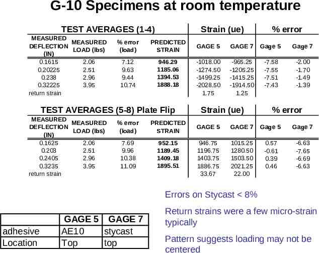
G-10 Specimens at room temperature TEST AVERAGES (1-4) MEASURED MEASURED DEFLECTION LOAD (lbs) (IN) 0.1615 2.06 0.20225 2.51 0.238 2.96 0.32225 3.95 return strain Strain (ue) % error (load) PREDICTED STRAIN 7.12 9.63 9.44 10.74 946.29 1185.06 1394.53 1888.18 TEST AVERAGES (5-8) Plate Flip MEASURED MEASURED DEFLECTION LOAD (lbs) (IN) 0.1625 2.06 0.203 2.51 0.2405 2.96 0.3235 3.95 return strain % error (load) PREDICTED STRAIN 7.69 9.96 10.38 11.09 952.15 1189.45 1409.18 1895.51 % error GAGE 5 GAGE 7 Gage 5 Gage 7 -1018.00 -1274.50 -1499.25 -2028.50 1.75 -965.25 -1205.25 -1415.25 -1914.50 1.25 -7.58 -7.55 -7.51 -7.43 -2.00 -1.70 -1.49 -1.39 Strain (ue) % error GAGE 5 GAGE 7 Gage 5 Gage 7 946.75 1196.75 1403.75 1886.75 33.67 1015.25 1280.50 1503.50 2021.25 22.00 0.57 -0.61 0.39 0.46 -6.63 -7.65 -6.69 -6.63 Errors on Stycast 8% adhesive Location GAGE 5 GAGE 7 AE10 stycast Top top Return strains were a few micro-strain typically Pattern suggests loading may not be centered
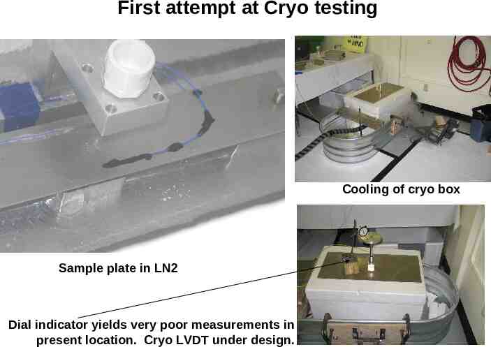
First attempt at Cryo testing Cooling of cryo box Sample plate in LN2 Dial indicator yields very poor measurements in present location. Cryo LVDT under design.
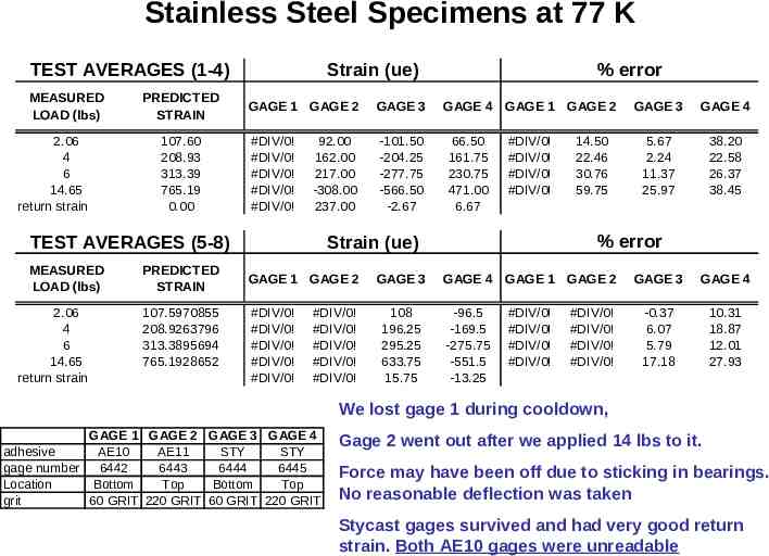
Stainless Steel Specimens at 77 K TEST AVERAGES (1-4) MEASURED LOAD (lbs) 2.06 4 6 14.65 return strain PREDICTED STRAIN 107.60 208.93 313.39 765.19 0.00 Strain (ue) GAGE 1 GAGE 2 GAGE 3 #DIV/0! #DIV/0! #DIV/0! #DIV/0! #DIV/0! -101.50 -204.25 -277.75 -566.50 -2.67 92.00 162.00 217.00 -308.00 237.00 TEST AVERAGES (5-8) MEASURED LOAD (lbs) 2.06 4 6 14.65 return strain PREDICTED STRAIN 107.5970855 208.9263796 313.3895694 765.1928652 % error GAGE 4 GAGE 1 GAGE 2 GAGE 3 GAGE 4 #DIV/0! #DIV/0! #DIV/0! #DIV/0! 5.67 2.24 11.37 25.97 38.20 22.58 26.37 38.45 66.50 161.75 230.75 471.00 6.67 % error Strain (ue) GAGE 1 GAGE 2 #DIV/0! #DIV/0! #DIV/0! #DIV/0! #DIV/0! #DIV/0! #DIV/0! #DIV/0! #DIV/0! #DIV/0! GAGE 3 108 196.25 295.25 633.75 15.75 14.50 22.46 30.76 59.75 GAGE 4 GAGE 1 GAGE 2 GAGE 3 GAGE 4 #DIV/0! #DIV/0! #DIV/0! #DIV/0! -0.37 6.07 5.79 17.18 10.31 18.87 12.01 27.93 -96.5 -169.5 -275.75 -551.5 -13.25 #DIV/0! #DIV/0! #DIV/0! #DIV/0! We lost gage 1 during cooldown, GAGE 1 GAGE 2 GAGE 3 GAGE 4 adhesive AE10 AE11 STY STY gage number 6442 6443 6444 6445 Location Bottom Top Bottom Top grit 60 GRIT 220 GRIT 60 GRIT 220 GRIT Gage 2 went out after we applied 14 lbs to it. Force may have been off due to sticking in bearings. No reasonable deflection was taken Stycast gages survived and had very good return strain. Both AE10 gages were unreadable
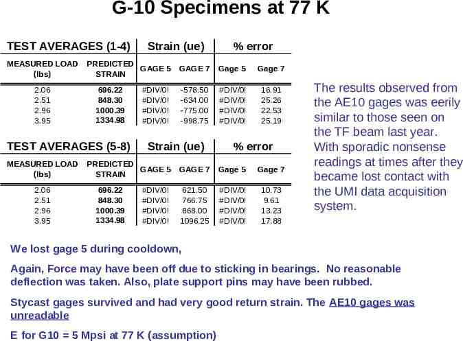
G-10 Specimens at 77 K TEST AVERAGES (1-4) MEASURED LOAD (lbs) 2.06 2.51 2.96 3.95 PREDICTED GAGE 5 STRAIN 696.22 848.30 1000.39 1334.98 TEST AVERAGES (5-8) MEASURED LOAD (lbs) 2.06 2.51 2.96 3.95 Strain (ue) #DIV/0! #DIV/0! #DIV/0! #DIV/0! 696.22 848.30 1000.39 1334.98 GAGE 7 Gage 5 Gage 7 -578.50 -634.00 -775.00 -998.75 #DIV/0! #DIV/0! #DIV/0! #DIV/0! 16.91 25.26 22.53 25.19 Strain (ue) PREDICTED GAGE 5 STRAIN #DIV/0! #DIV/0! #DIV/0! #DIV/0! % error % error GAGE 7 Gage 5 Gage 7 621.50 766.75 868.00 1096.25 #DIV/0! #DIV/0! #DIV/0! #DIV/0! 10.73 9.61 13.23 17.88 The results observed from the AE10 gages was eerily similar to those seen on the TF beam last year. With sporadic nonsense readings at times after they became lost contact with the UMI data acquisition system. We lost gage 5 during cooldown, Again, Force may have been off due to sticking in bearings. No reasonable deflection was taken. Also, plate support pins may have been rubbed. Stycast gages survived and had very good return strain. The AE10 gages was unreadable E for G10 5 Mpsi at 77 K (assumption)
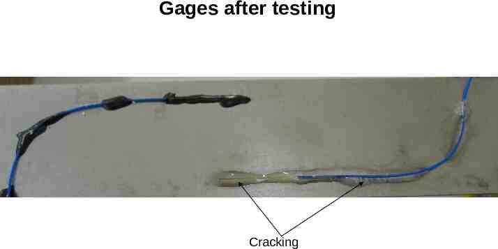
Gages after testing Cracking
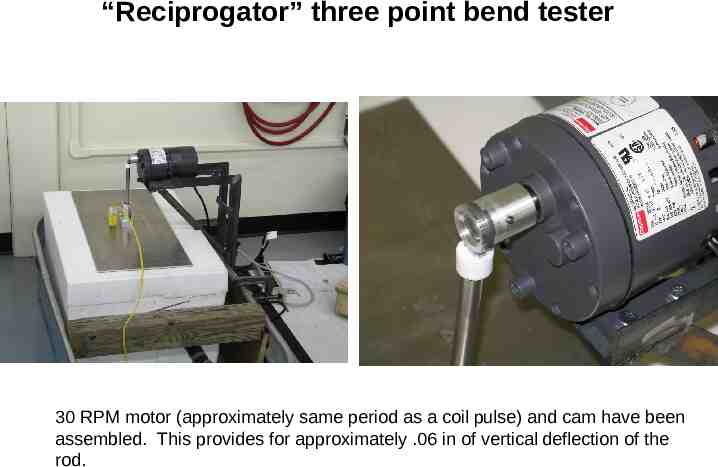
“Reciprogator” three point bend tester 30 RPM motor (approximately same period as a coil pulse) and cam have been assembled. This provides for approximately .06 in of vertical deflection of the rod.
What is the modulus of SS. ? participants Source: In our case, Small changes in deflection load, produce large changes in modulus and thus predicted strain. Such a wide array of data for the modulus of stainless steel.