RAJEEV GANDHI MEMORIAL COLLEGE OF ENGINEERING AND TECHNOLOGY DEPATMENT


60 Slides3.61 MB
RAJEEV GANDHI MEMORIAL COLLEGE OF ENGINEERING AND TECHNOLOGY DEPATMENT OF CIVIL ENGINEERING Design of GLACIS weir Dr G Sreenivasulu 03/21/2024 1
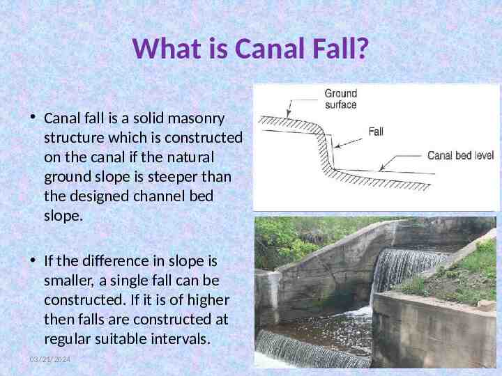
What is Canal Fall? Canal fall is a solid masonry structure which is constructed on the canal if the natural ground slope is steeper than the designed channel bed slope. If the difference in slope is smaller, a single fall can be constructed. If it is of higher then falls are constructed at regular suitable intervals. 03/21/2024 2
Location of Canal Falls Location of canal fall depends upon the following factors – Topography of canal – Economy of excavation or filling The above two will decide the location of canal fall across canal. By understanding topographic condition we can provide the required type of fall which will give good results. At the same time, the provided falls is economical and more useful. So, economical calculation is also important. Unbalanced earth work on upstream and downstream result the project more uneconomical. 03/21/2024 3
Types of Canal Falls and their Importance The important types of falls which were used in olden days and those which are being used in modern days are described below: – Ogee falls – Rapid fall – Stepped falls – Trapezoidal notch falls – Well type falls – Simple vertical drop falls – Straight glacis falls – Montague type falls – English falls or baffle falls 03/21/2024 4
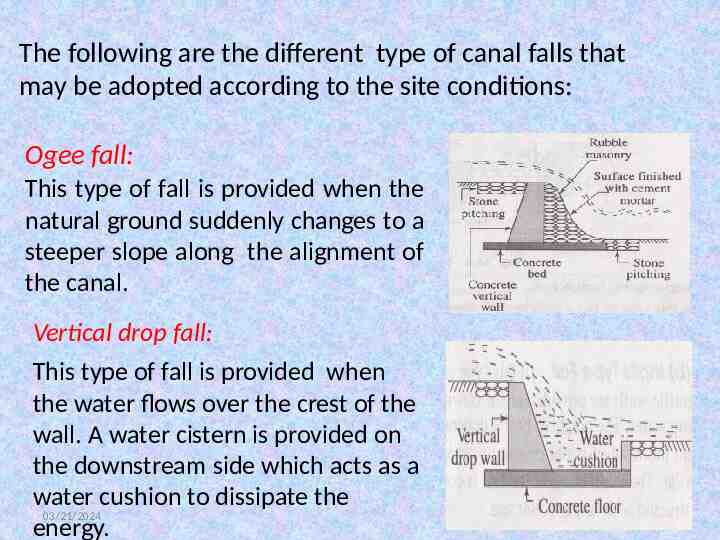
The following are the different type of canal falls that may be adopted according to the site conditions: Ogee fall: This type of fall is provided when the natural ground suddenly changes to a steeper slope along the alignment of the canal. Vertical drop fall: This type of fall is provided when the water flows over the crest of the wall. A water cistern is provided on the downstream side which acts as a water cushion to dissipate the 03/21/2024 energy. 5
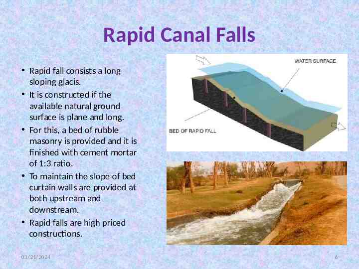
Rapid Canal Falls Rapid fall consists a long sloping glacis. It is constructed if the available natural ground surface is plane and long. For this, a bed of rubble masonry is provided and it is finished with cement mortar of 1:3 ratio. To maintain the slope of bed curtain walls are provided at both upstream and downstream. Rapid falls are high priced constructions. 03/21/2024 6
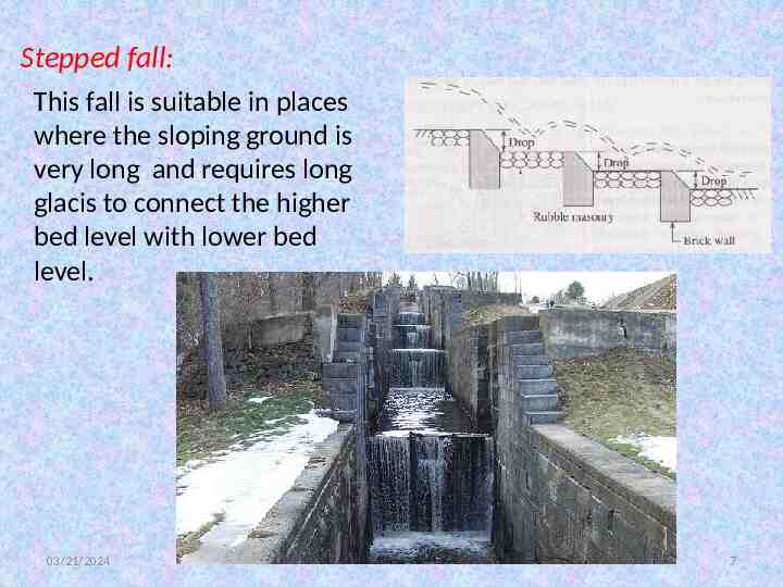
Stepped fall: This fall is suitable in places where the sloping ground is very long and requires long glacis to connect the higher bed level with lower bed level. 03/21/2024 7
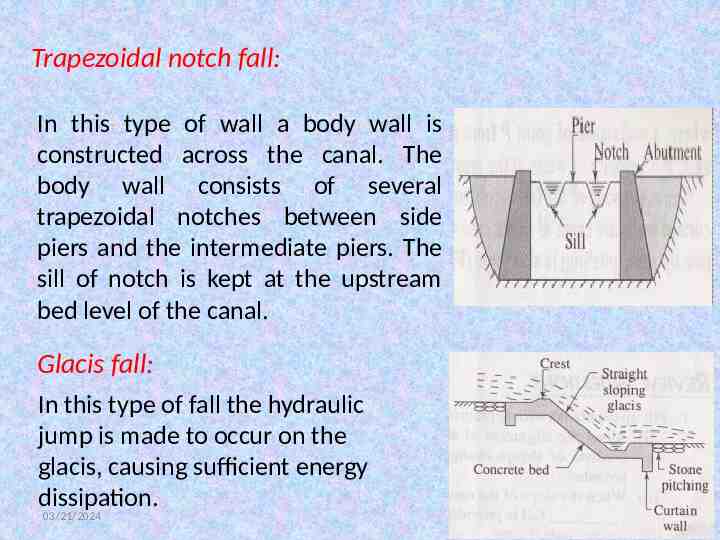
Trapezoidal notch fall: In this type of wall a body wall is constructed across the canal. The body wall consists of several trapezoidal notches between side piers and the intermediate piers. The sill of notch is kept at the upstream bed level of the canal. Glacis fall: In this type of fall the hydraulic jump is made to occur on the glacis, causing sufficient energy dissipation. 03/21/2024 8
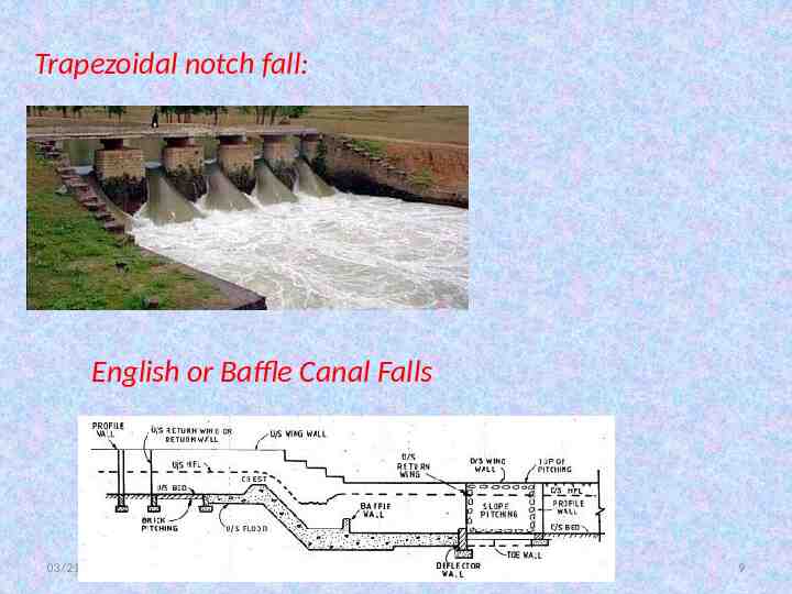
Trapezoidal notch fall: English or Baffle Canal Falls 03/21/2024 9
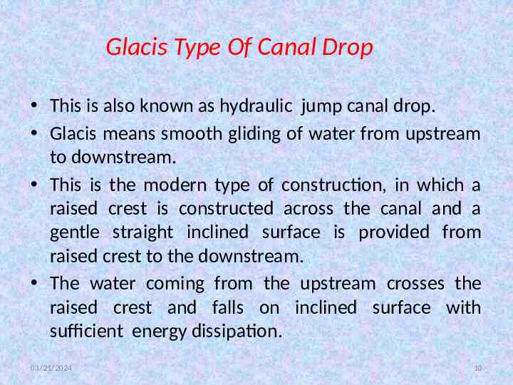
Glacis Type Of Canal Drop This is also known as hydraulic jump canal drop. Glacis means smooth gliding of water from upstream to downstream. This is the modern type of construction, in which a raised crest is constructed across the canal and a gentle straight inclined surface is provided from raised crest to the downstream. The water coming from the upstream crosses the raised crest and falls on inclined surface with sufficient energy dissipation. 03/21/2024 10
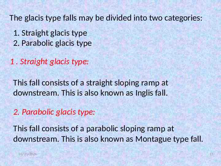
The glacis type falls may be divided into two categories: 1. Straight glacis type 2. Parabolic glacis type 1 . Straight glacis type: This fall consists of a straight sloping ramp at downstream. This is also known as Inglis fall. 2. Parabolic glacis type: This fall consists of a parabolic sloping ramp at downstream. This is also known as Montague type fall. 03/21/2024 11
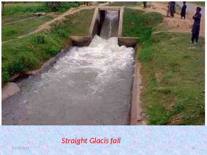
Straight Glacis fall 03/21/2024 12
Parabolic Glacis Fall 03/21/2024 13
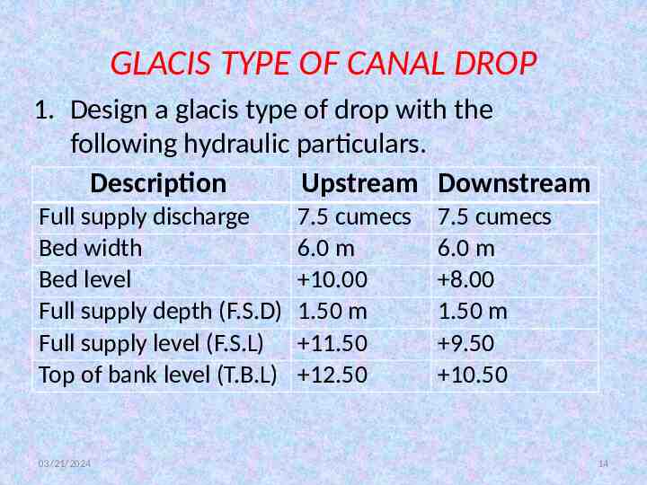
GLACIS TYPE OF CANAL DROP 1. Design a glacis type of drop with the following hydraulic particulars. Description Upstream Downstream Full supply discharge Bed width Bed level Full supply depth (F.S.D) Full supply level (F.S.L) Top of bank level (T.B.L) 03/21/2024 7.5 cumecs 6.0 m 10.00 1.50 m 11.50 12.50 7.5 cumecs 6.0 m 8.00 1.50 m 9.50 10.50 14
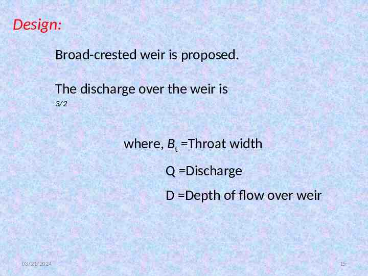
Design: Broad-crested weir is proposed. The discharge over the weir is 3/2 where, Bt Throat width Q Discharge D Depth of flow over weir 03/21/2024 15
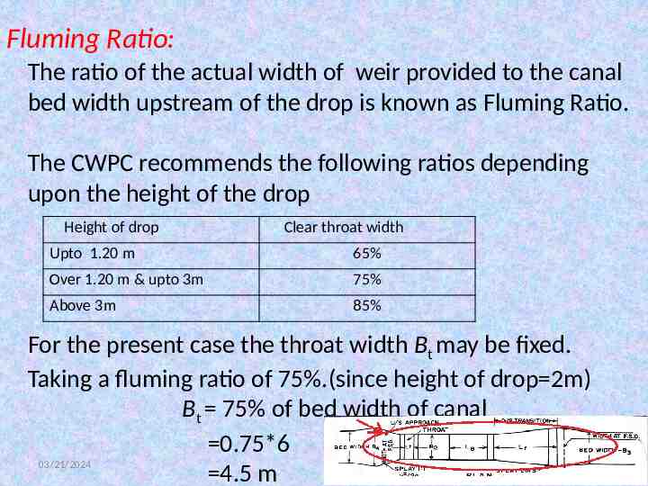
Fluming Ratio: The ratio of the actual width of weir provided to the canal bed width upstream of the drop is known as Fluming Ratio. The CWPC recommends the following ratios depending upon the height of the drop Height of drop Clear throat width Upto 1.20 m 65% Over 1.20 m & upto 3m 75% Above 3m 85% For the present case the throat width Bt may be fixed. Taking a fluming ratio of 75%.(since height of drop 2m) Bt 75% of bed width of canal 0.75*6 03/21/2024 16 4.5 m
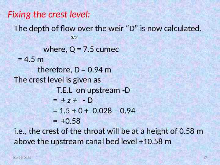
Fixing the crest level: The depth of flow over the weir “D” is now calculated. 3/2 where, Q 7.5 cumec 4.5 m therefore, D 0.94 m The crest level is given as T.E.L on upstream -D z -D 1.5 0 0.028 – 0.94 0.58 i.e., the crest of the throat will be at a height of 0.58 m above the upstream canal bed level 10.58 m 03/21/2024 17
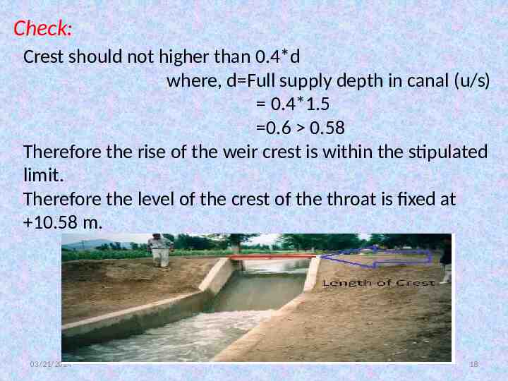
Check: Crest should not higher than 0.4*d where, d Full supply depth in canal (u/s) 0.4*1.5 0.6 0.58 Therefore the rise of the weir crest is within the stipulated limit. Therefore the level of the crest of the throat is fixed at 10.58 m. 03/21/2024 18
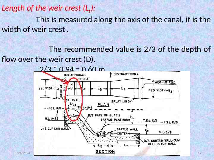
Length of the weir crest (Lt): This is measured along the axis of the canal, it is the width of weir crest . The recommended value is 2/3 of the depth of flow over the weir crest (D). 2/3 * 0.94 0.60 m 03/21/2024 19
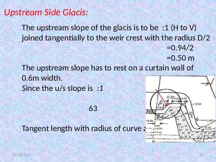
Upstream Side Glacis: The upstream slope of the glacis is to be :1 (H to V) joined tangentially to the weir crest with the radius D/2 0.94/2 0.50 m The upstream slope has to rest on a curtain wall of 0.6m width. Since the u/s slope is :1 63 Tangent length with radius of curve as 0.50 m is 03/21/2024 20
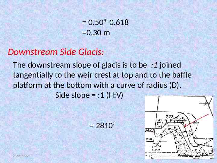
0.50* 0.618 0.30 m Downstream Side Glacis: The downstream slope of glacis is to be :1 joined tangentially to the weir crest at top and to the baffle platform at the bottom with a curve of radius (D). Side slope :1 (H:V) 2810’ 03/21/2024 21
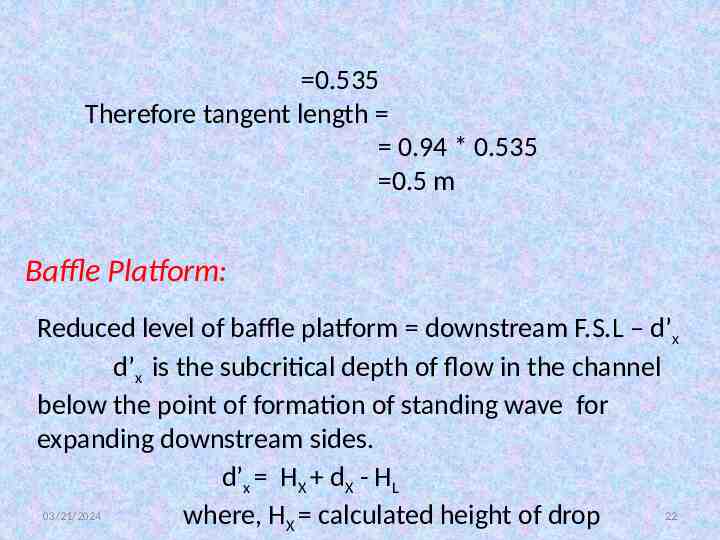
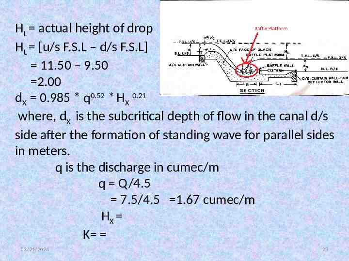
0.535 Therefore tangent length 0.94 * 0.535 0.5 m Baffle Platform: Reduced level of baffle platform downstream F.S.L – d’x d’x is the subcritical depth of flow in the channel below the point of formation of standing wave for expanding downstream sides. d’x HX dX - HL 03/21/2024 22 where, HX calculated height of drop
HL actual height of drop HL [u/s F.S.L – d/s F.S.L] 11.50 – 9.50 2.00 dX 0.985 * q0.52 * HX 0.21 where, dX is the subcritical depth of flow in the canal d/s side after the formation of standing wave for parallel sides in meters. q is the discharge in cumec/m q Q/4.5 7.5/4.5 1.67 cumec/m HX K 03/21/2024 23
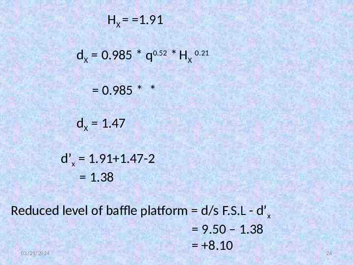
HX 1.91 dX 0.985 * q0.52 * HX 0.21 0.985 * * dX 1.47 d’x 1.91 1.47-2 1.38 Reduced level of baffle platform d/s F.S.L - d’x 9.50 – 1.38 8.10 03/21/2024 24
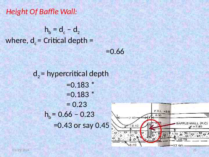
Height Of Baffle Wall: hb dc – d2 where, dc Critical depth 0.66 d2 hypercritical depth 0.183 * 0.183 * 0.23 hb 0.66 – 0.23 0.43 or say 0.45 03/21/2024 25
Top level of the baffle wall 8.10 0.45 8.55 Thickness of baffle wall generally taken as of hb * 0.45 0.3 m Length of baffle platform) is generally taken as 5.25 * hb 5.25 *0.45 2.36 say 2.40 The baffle platform is joint to the baffle wall with a curve of radius of i.e., 0.30 m. 03/21/2024 26
Design Of Cistern: The platform below the baffle wall upto the deflector wall is known as cistern. Generally, this will be at a level lower than that of the baffle platform and canal bed level downstream of drop. The depth of the cistern is adopted as 0.1 below the canal bed level, where is the full supply depth of the downstream of the drop subjected to a minimum of 15 cm in minor channels and 30 cm for main canals and branches. 03/21/2024 27
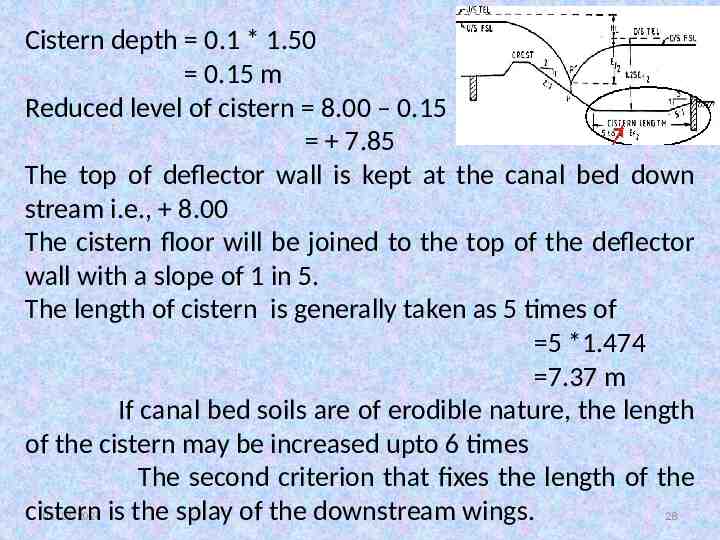
Cistern depth 0.1 * 1.50 0.15 m Reduced level of cistern 8.00 – 0.15 7.85 The top of deflector wall is kept at the canal bed down stream i.e., 8.00 The cistern floor will be joined to the top of the deflector wall with a slope of 1 in 5. The length of cistern is generally taken as 5 times of 5 *1.474 7.37 m If canal bed soils are of erodible nature, the length of the cistern may be increased upto 6 times The second criterion that fixes the length of the 03/21/2024 is the splay of the downstream wings. 28 cistern
The wings are splayed from the baffle wall with a splay of 1 in 5, such that the distance between the returns at the end of the splay is equal to the full supply width of the canal water way. Assuming 1 to 1 canal cutting, the width of water way at canal F.S.L 6 2*1.5 9m 11.25 m This fixes the length of the cistern from the baffle wall upto end of deflector wall. 03/21/2024 29
Upstream Canal Transition: The upstream canal wings are splayed at 1 in 1. The length of transition *1 2.25 m Protective Works: Revetments And Bed Pitching: Upstream side of the drop: The length of side revetments is taken as 3 times the upstream side full supply depth, i.e., 3*1.5 4.5m Bed pitching is generally restricted to half the length of the side revetments, i.e., 2.25 m 03/21/2024 30
Downstream side of the drop: The length of side revetments is taken as 3 times the downstream side full supply depth, i.e., 3*1.5 4.5m Bed pitching is generally restricted to half the length of the side revetments, i.e., 2.25 m Upstream Side Curtain Wall: The depth of the curtain wall at the end of the upstream end of the sloping glacis is given as 1/3 of the upstream side full supply depth. i.e., 0.5 m below the upstream canal bed. 03/21/2024 31
Downstream cutoff wall below Deflector Wall: This is generally taken down to a depth of ½ the full supply depth below the canal bed level downstream. i.e., 8.00 – 0.75 7.25 Scour Depths: The depths of curtain walls u/s and d/s of the drop are governed by Scour depth. While the u/s curtain wall is taken down to 1.00 to 1.25 times the scour depth, the d/s curtain wall is taken down to a depth of 1.5 times the scour depth. Scour depth is given by the formula 03/21/2024 32
Where, R depth of scour below the maximum water level q discharge per meter run in cumecs f silt factor usually taken as 1.00 Checking the upstream curtain wall for scour depth: Assuming the length of the curtain wall , same as that of the weir crest, i.e., 4.5 m. Discharge per meter run cumecs R 1.374 * 1.408 1.934 1.25 times R 1.25 * 1.934 2.42 m 03/21/2024 33
Reduced level of the bottom of the curtain wall 11.50 – 2.42 9.08 Checking the downstream curtain wall for scour depth: The length of the curtain wall is equal to the length of the deflector wall i.e., 9 m. discharge per meter run 0.833 cumecs 1.374 * 0.8855 1.22 m 1.5 * R 1.5 * 1.22 1.83 m Reduced level of the bottom of the d/s cutoff wall 9.50 – 1.83 7.67 03/21/2024 34
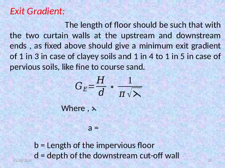
Exit Gradient: The length of floor should be such that with the two curtain walls at the upstream and downstream ends , as fixed above should give a minimum exit gradient of 1 in 3 in case of clayey soils and 1 in 4 to 1 in 5 in case of pervious soils, like fine to course sand. 𝐻 1 𝐺𝐸 𝑑 𝜋 Where , a b Length of the impervious floor d depth of the downstream cut-off wall 03/21/2024 35
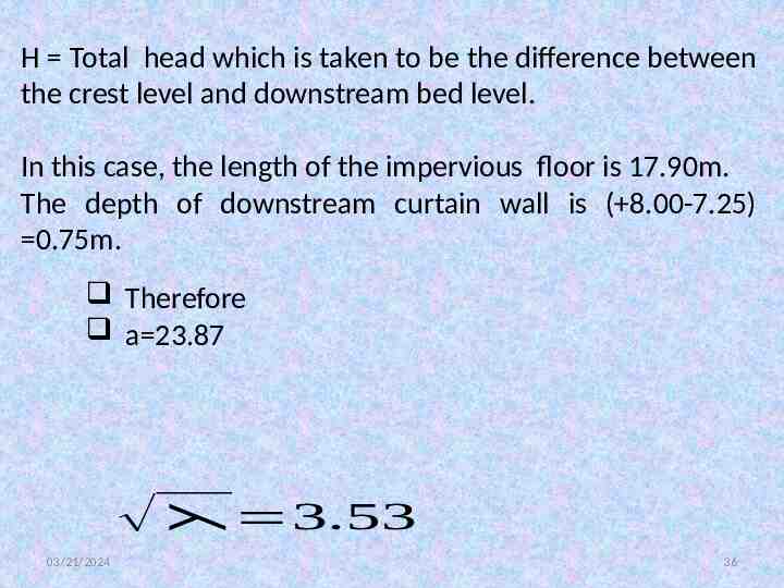
H Total head which is taken to be the difference between the crest level and downstream bed level. In this case, the length of the impervious floor is 17.90m. The depth of downstream curtain wall is ( 8.00-7.25) 0.75m. Therefore a 23.87 3.53 03/21/2024 36
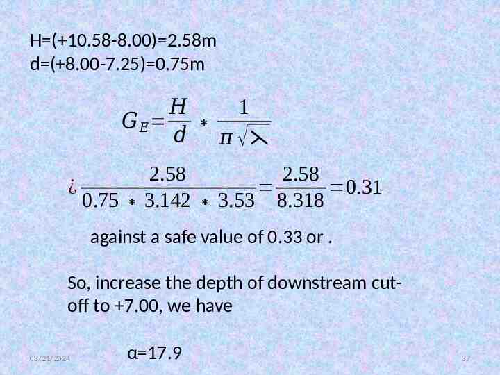
H ( 10.58-8.00) 2.58m d ( 8.00-7.25) 0.75m 𝐻 1 𝐺𝐸 𝑑 𝜋 2.58 2.58 ¿ 0.31 0.75 3.142 3.53 8.318 against a safe value of 0.33 or . So, increase the depth of downstream cutoff to 7.00, we have 03/21/2024 α 17.9 37
Therefore This is less than and hence may be adopted. 03/21/2024 38
Energy dissipation Arrangements: The C.W.P.C recommends the following arrangements. a) In case of a vertical fall, for discharges exceeding 10 cumecs, two rows of friction blocks staggered in plan may be provided in the cistern so that the downstream side edge of the downstream side row is at a distance of from the end of the cistern floor. b) Glacis fall(without baffle): Four rows of blocks may be provided in the case of flummed falls only. These may be staggered in plan. The suitable dimensions of the blocks are as follows: 03/21/2024 39
Height, h Length, Distance between rows h c)Glacis fall (with baffle): Two rows of friction blocks may be provided only when the drop exceeds 2m. The upstream side edge of the upstream side row may be at a distance of from the end of the cistern floor. These are staggered in plan. Height, Length h Top width Distance between rows h. 03/21/2024 40
d)Glacis blocks: The effect of these is to reduce the turbulence in flow which in turn reduces wave wash, thus ensuring uniform flow. A single row of glacis blocks of the same dimensions as friction blocks may be provided in the case of falls with drop more than 2m. e)Deflector wall: The deflector wall of height provided at the downstream end of cistern helps in piling up the bed material against the curtain wall, which ensures the safety of the curtain wall. The minimum height should be 0.15m. The top of deflector wall is joined to the cistern floor with a gentle slope of 1 in 5. 03/21/2024 41
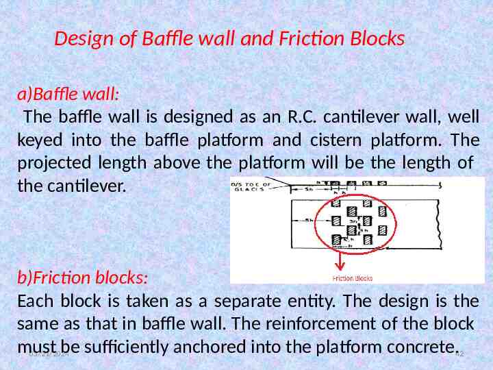
Design of Baffle wall and Friction Blocks a)Baffle wall: The baffle wall is designed as an R.C. cantilever wall, well keyed into the baffle platform and cistern platform. The projected length above the platform will be the length of the cantilever. b)Friction blocks: Each block is taken as a separate entity. The design is the same as that in baffle wall. The reinforcement of the block must be sufficiently anchored into the platform concrete.42 03/21/2024
Checking the Thickness of baffle platform, cistern and the glacis: The Maximum uplift head acting on the floor of the structure is, when the canal is empty with upstream water level at weir crest and downstream water level at canal bed level. i.e., the uplift head (10.58-8.00) 2.58m The Key points where residual uplift pressures are to be determined are: Under the toe of Glacis Under the baffle wall Center of the cistern Downstream end of the cistern ,i.e., just upstream of the end curtain wall 03/21/2024 43
Under the toe of the glacis: 20 60* Taking 75% as effective, the percentage of pressure is: Uplift head Thickness Required 03/21/2024 44
Under the baffle wall: Uplift pressure Taking 7% as effective, the pressure Therefore Uplift Head Thickness required 03/21/2024 45
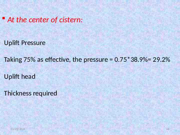
At the center of cistern: Uplift Pressure Taking 75% as effective, the pressure 0.75*38.9% 29.2% Uplift head Thickness required 03/21/2024 46
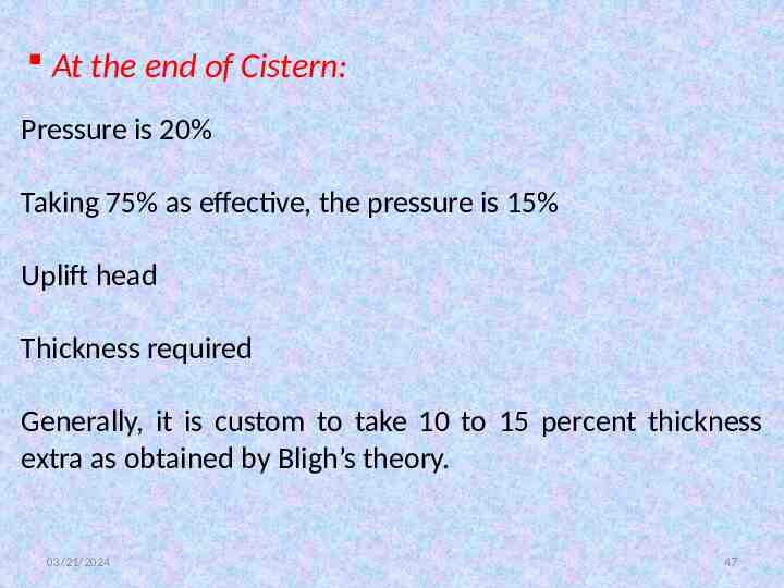
At the end of Cistern: Pressure is 20% Taking 75% as effective, the pressure is 15% Uplift head Thickness required Generally, it is custom to take 10 to 15 percent thickness extra as obtained by Bligh’s theory. 03/21/2024 47
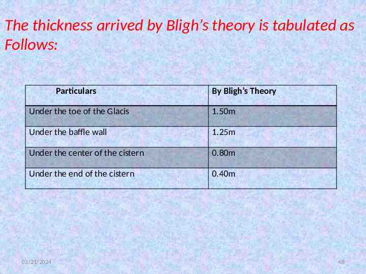
The thickness arrived by Bligh’s theory is tabulated as Follows: Particulars By Bligh’s Theory Under the toe of the Glacis 1.50m Under the baffle wall 1.25m Under the center of the cistern 0.80m Under the end of the cistern 0.40m 03/21/2024 48
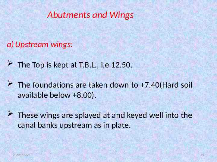
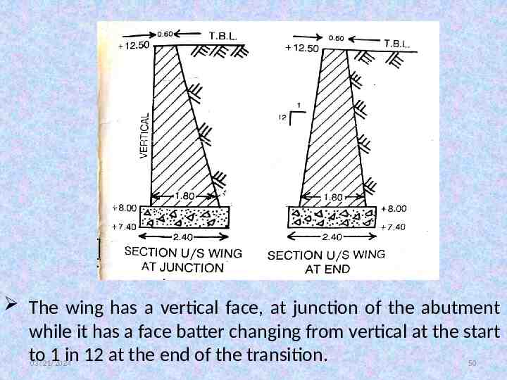
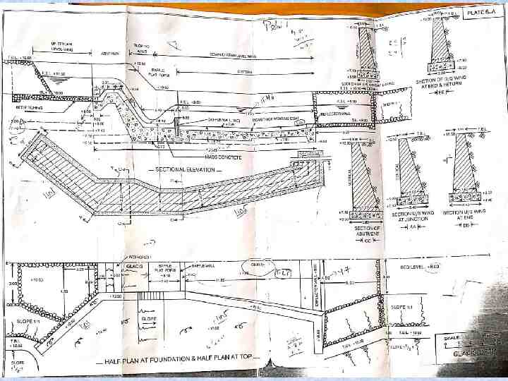
Abutments and Wings a) Upstream wings: The Top is kept at T.B.L., i.e 12.50. The foundations are taken down to 7.40(Hard soil available below 8.00). These wings are splayed at and keyed well into the canal banks upstream as in plate. 03/21/2024 49
The wing has a vertical face, at junction of the abutment while it has a face batter changing from vertical at the start to 1 in 12 at the end of the transition. 03/21/2024 50
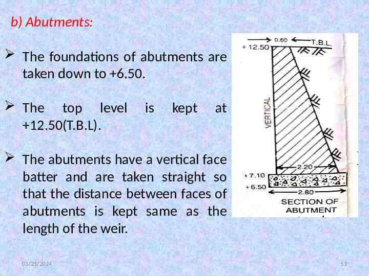
b) Abutments: The foundations of abutments are taken down to 6.50. The top level 12.50(T.B.L). is kept at The abutments have a vertical face batter and are taken straight so that the distance between faces of abutments is kept same as the length of the weir. 03/21/2024 51
c) Sloping wing: The Section of wing at junction of abutment is the same as the abutment taken down to level at foundation 6.50 with top level 12.50. The face batter is vertical in continuation of the abutment. The Section of wing at the end of slope and the junction with level wing also is taken down to 6.50(foundation). The Top of level wing is kept at T.B.L. downstream. i.e. at 10.50. The level wing also has a vertical face till the end of the baffle wall. 03/21/2024 52
d) Level Wing and return : The level wing and return beyond the baffle wall are taken down to a level of 6.50(at foundation). The Top level is kept right through at 10.50. The wing wall is warped with the face batter changing from a vertical face batter at the baffle wall, to a face batter of 1 in 12 at the end of the splay, i.e., at the deflector wall. The returns have a face batter of 1 in 12 right through and are well keyed into the canal banks downstream of the drop. 03/21/2024 53
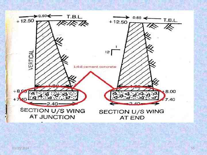
Specifications: a) Foundations, glacis, downstream cistern apron and upstream and downstream cut-offs: The foundations of upstream and downstream wing walls and abutments are all laid in cement concrete 1:4:8. The Sloping glacis in between the abutments is however laid in cement concrete 1:3:6(M100). Economy can be effected by replacing 20 percent of cement with fly ash. 03/21/2024 54
03/21/2024 55
The Top 15 cm thick coat(wearing coat) on the crest and sloping glacis and the cistern and apron is laid in a rich mix, i.e.,either in CC 1:1 or in CC 1:2:4 to withstand the super-critical velocities developed due to the drop. b)The baffle wall and the Friction blocks: These two items will be in reinforced concrete 1:1:3 or 1:2:4 matching with proportion of the wearing coat. 03/21/2024 56
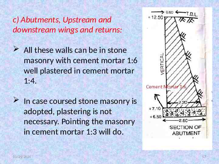
c) Abutments, Upstream and downstream wings and returns: All these walls can be in stone masonry with cement mortar 1:6 well plastered in cement mortar 1:4. In case coursed stone masonry is adopted, plastering is not necessary. Pointing the masonry in cement mortar 1:3 will do. 03/21/2024 57
Causes For Failure: Improper energy dissipation below the drop, creating super critical velocities beyond the solid apron. This creates scours at the downstream end of apron, consequently under mining the solid apron and the returns and downstream Talus. Therefore, providing sufficient solid apron, as per the suggested principles in the design is imperative. 03/21/2024 58
The thickness of solid apron has to withstand the impact of the falling water and also withstand the uplift pressures. Care should be taken to see that there is no residual uplift pressure at the end of solid apron. In case it is not possible to reduce the residual uplift, inspite of providing long length of apron, a cutoff pile at the end of solid apron may be provided, limiting the exit gradient to less than 1/5 or 1/7. 03/21/2024 59
03/21/2024 60